
Sbesk
Identifying Sensors?
Hey everyone!
I'm still completely new to this scene, and I was wondering if any of the old hands out there might be able to help me with figuring out what a couple of old sensors I just rediscovered in my junk bin might do. I'll try to post some pics, but in the meantime I'll just try to describe them... if they are what I want then I might be in luck for some free additions to yet another crappy robot!
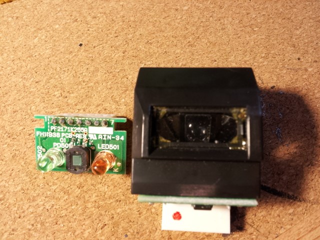
First subject is this really cool looking curved piece of plastic with a little window I found, and it appears that it encloses a 3-piece setup consisting of a green LED, a photocell, and a red LED. The setup is arranged so that when they are in the enclosure, the two LEDs shine onto angled mirrors that are focused onto a convex lens (could be one-sided or double, I can't see the bottom) that in turn sits on top of the photocell. Light through the main window shines onto another angled mirror that also is focused on the photocell. The chip everything is attached to has 7 leads or contact points, or whatever you guys call female plug in receptacles... holes?
The chip itself has the following labels: LED502, K, PD501, 01, A, K, LED501, K, and it looks like the board itself is PF2171K255A and FH11938 PCB-AES (backwards rj looking symbol) AIN-34.
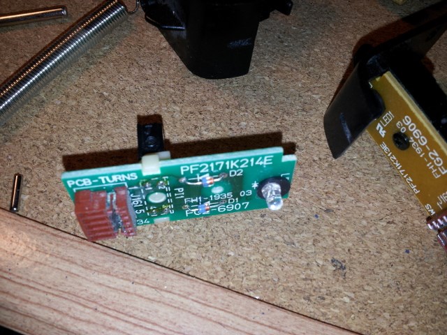
The other things I have are a million little beam-breaker or cliff type sensors consisting of a dark square LED and a clear LED... I understand how these work, but can they be angled in any way or used differently than just as two posts that need to be interrupted? I would love if I could somehow focus them to be forward looking distance or proximity sensors.
All of this stuff was out of a photocopier that someone gave me, full of stepper motors, sensors, and other weird things like solenoids and unknown styles of motors that sit on shafts. I literally have a pile of this junk now and I need to organize and purge.
I know I can just do some research on the net for this stuff, but I was wondering how real world applications have turned out, and specifically with the EZv3, and what pins I would connect to, what readings or values that might be applicable.
Thanks for any info in advance!

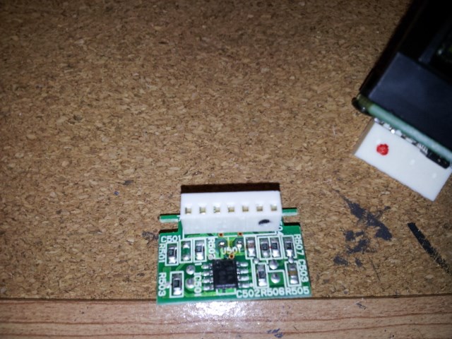
Now that I'm actually looking at it and thinking, it looks more like the red and green LEDs have mirrors that focus ahead of the enclosure, and the photocell probably picks up changes when something enters that focus... ? The more I think about the pins I would imagine the LEDs have 2 each and the photocell has 3 for whatever reason. Maybe? The chip on the back of the board has the numbers 814 546... which probably has something to do with whatever this gadget accomplishes.
Either way, I have 2 of these setups, and I am thinking I could use them either one front one back or 2 at 45deg for some fine obstacle avoidance.
This is apparently more exciting than superbowl for me. I suppose if it was rugby WC I would not be thinking about this.
I would simply google those Labels and see what comes up!
Datasheets shows the little chip on the back is a "Digital RGB Color Light Sensor with IR Blocking Filter"
Cool
SO... Seattle won, and all I could think about was the pins on the little board for my light sensors.
The next question, assuming these things for whatever reason are able to sense light and possibly distinguish color, is how would I try hooking it to the EZ?
Let's just say that the 2 outside pins on either side are for the LED's, which would mean they are powered up the entire time, so just any 2 power and ground pinouts on the EZ will do right?
That leaves the center pinout, which I am also assuming works the same as a Sharp IR distance sensor, so Gnd, Vcc, and signal out?
Just by looking at it, and with no idea how it actually works, the sensor itself has 2 pins coming off it soldered onto the board, and I would imagine the back of the sensor is probably ground... which would make the pin order something like Vcc, Gnd, vc(or whatever the term for signal power is- I have zero training here!).
So if I hook this up wrong, could any damage occur to the EZ? What is the best way of determining what does what? Other options could be hooking it to arduinos I have laying around, or using a breadboard and a multimeter somehow? Ha ha ha. Boy, this must sound dumb to you guys! All for a lame IR sensor!
You most definitely need the specs on those sensors so you can properly attach voltage and what the outputs are...otherwise your just guessing ..and sometime that means smoke!
Well, looks like I might be out of luck... I've spent a few days randomly trying new searches and even trying to find datasheets or wiring diagrams from these stupid old photocopiers. No dice.
Besides, I just picked up a craaaaaazy 1/6 scale RC tank off a guy on kijiji, which is going to make an outrageous base for a serious yard robot. I suppose I will just head to the one and only electronics store in Edmonton and buy some cheap sensors there, then move on with my droid engineer development.
Thanks anyways for your advice, irobot58!