
tevans
Brazil
Asked
— Edited
Help! My Ez-B Does Not Respond To Any Command!
DJ! (and Friends!), please I need your help. I had an accident with my V3 (my little son STEP (!) on it while I was installing at the base of a robot!).. so, as a result, it broke two legs of the Power regulator (LM1084). So, I carefuly removed it, and soldered it back. Well, the board Lit up, connected to ARC... BUT it flows NO power to the servos, (D0 to D19 receive no power at all!)
Do you think something else could have brake ? like some circuit path or something ?! I examined and could not find any other damage... and the voltage is getting correctly to the power regulators....
ANY HEEEELLLP!?!
thanks...

No need to double post the same question on multiple threads my friend. Its always a good practice to start a new thread and stick to that one.
Anyways, sorry to read about your problem. Kids are quick and don't always watch where they step.
Look carefully at all other parts for cracks in solder joints. Its possible something else got damaged. How are your soldering, desoldering skills? Its possible you could have damaged the board or the regulator with too much heat during the repair. You may need a new regulator if it's bad or replace the trace with a jumper if you damaged the board. tired
Thanks Dave... As far as I notice, the regulators are functional. so I think I must replace the trace in some point. The case is: how to find out where repair it ? thanks for any help.
P.s -sorry about the duplicated post.. I just deleted it !
Try connecting your volt meter to Gnd with the negative lead and then use a sewing needle connected to the positive lead and press into the copper trace from the 5v regulator. Keep following the trace until you don't have 5 volts. Then with a magnifying glass look for the break in the foil.
Doc, that's a fine method. I'll have to put that one in my tool box.
Another way to isolate the trace that's causing the problem is with a continuity test. Every good multimeter has the ability to check if there is a connections from one point to another. You don't have to have the board powered up for this one. Start by placing the tester in continuity test mode and put one test lead on one of the legs of the regulator. Then put the other test lead on the trace just outside the solder joint. You can use Doc's needle idea to get through the paint over the trace. This will test if signal or power is getting from that leg through the soldered hole into the trace. Test all legs of the regulator like that. Next leave the one lead on a leg and move to the end of the trace where it's connected to the next component. Test the legs of that component like you did the regulator's legs. Then move through the circuit like that till you get to the power output pin, chip leg or ground circuit. Do this for each leg and trace of the regulator.
I Will try it ! And let you know any results! Thanks
No success... I could no find where the circuit is interrupted.. The power does not get to the D pins... So, I tried to insert an external 5v straight to the external input and the board worked! Well, do you think I can sold an jump wire from the regulator output to the first D 5v pin ?! Thanks...
First, test to see if you are really getting 5vdc from the center leg of VR1. Place your multi tester on DC voltage and put one test lead on the center LEG of the regulator and one on a ground on the board. Then and only then will you know you are starting out with voltage.
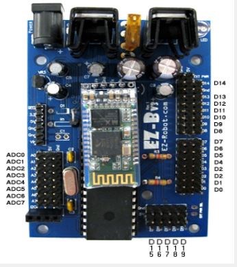
I'm fortunate enough to have a blank V3 EZB board and it's easy for me to trace this 5v circuit out. I had a little time and took a look this afternoon. The traces are huge so I find it hard to believe one could be open mid run. If anything you could have a torn trace at hole where you replaced a component. Do you have 5v at the center pins of the ADC ports? The feed go in two directions from the center leg of VR1. Downward feeds 5v to the ADC ports and 12c port and upward feeds the Digital pins 5v.
Follow along.
The 5+vdc starts at the center leg of the regulator on the upper left side of the board labeled VR1 and feeds both up and down from this hole
Going down this leg is tied to the + side of a cap just below it labeled C7. It then feeds to and through the 6 pin header on the left center of the board marked with different voltages. After passing through the 5v pin the trace drops down to the center pins of the ADC ports and then ends at the 5v pin of the 12c port.
The upward 5v trace takes off up and past an empty hole just above VR1. I'd look very close at the trace between these two holes. The power feeds through the board a couple times as it travels from the leg of the regulator and past the empty hole just above it. You may have torn the through the board connection or the small trace between the two holes when you removed the old regulator.
The trace then turns right and then down through the area between the main chip and the digital ports D0 - D14 and continues all the way to the bottom right of the board to the two empty holes you see there labeled EXT PWR.
About half way down this run between the main chip and the digital ports D0 - D14 there are two resistors labeled R3 & R4 that tap off this 5v line and feed a lower power over to the SCL & SDA pins of the 12C port on the lower left side of EZB. These taps shouldn't effect your power feed unless the trace is broken at one of these two locations.
After the trace passes the empty holes labeled EXT PWR the feed tees off to the left and also up to feed the center pins beyond D0 and D19 in a serial configuration.
So to answer your question; As long as you're reading 5vdc on the bottom of the board where the center pin of VR1 comes through, yes you can jumper to any center pin of any digital or ADC port depending which side is out or jump to both sides if needed. However please get your continuity tester out and test the path I've laid out for you. There should be a direct connection from the center leg (testing from the top of the board) of VR1 to the center pin of D0 and D19. If not back up step by step and see where it stops. That's where you should really install your jumper.
Hope this helps and let me know what you find.
Dave! You are great! Thanks for ll the time you spent on this! I'll try your solution right away! And let you know the results,
Thanks!