Help Controling Diverse Electronincs H Bridge
Hi Folks,
I want to use my Diverse Electronics motor controller for torso rotation on my B9 robot. I have it connected using 1 signal wire from port D1 on my EZ B V3 to the 'ch1' input on the Diverse Electronics controller. I want to use joystick #2 on a game controller that currently is configured to control my Sabertooth 2x25 via joystick #1 (controlling the Sabertooth movement panel). Trouble is I have no idea what the 'min' and 'max' values in the joystick #2 configuration panel mean and why the torso rotation motor moves erratically when I experiment with them OR if I should be using 'X' AND 'Y' OR 'Multi Servo'.
Heck I'm not even sure if I am connected to the DE controller correctly (dont know if it can even make use of serial data, etc). When I used this controller before with my Futaba RC unit, I hand channels 1 and 2 connected and it worked great with the joystick on the Futaba RC unit. I can't find the documentation for the DE controller and they seem to be defunct.
Anyone know how this controller works? Can it use digital data? Can I configure joystick 2 to make it operate in both directions? (full on, reverse, full on would be fine).
Do I need to control it using two digital ports? OR one or two analog ports? If I need to use the analog ports cant they be addressed from the joystick configuration panel?
I'm so lost... I've been working a lot and have pulled a few all nighters to get the G-Bot reconfigured for Halloween and just have not had time to try and learn more about this stuff (fell asleep each time I started so far... lol).
Feeling a little stressed right now. My Son is looking forward to seeing the G-Bot patrolling outside and interacting with trick or Treaters and I am a bit worried I may have bitten off more than I can chew (at least in that time frame)...
Any help is appreciated as always...
Gwen

Bear with me as my eyes are getting heavy and I seriously need to get some sleep.
The Analogue ports are inputs to the EZ-B, they read sensors etc. they are not output and do not control anything.
You can use the joysticks for anything you want really but it may need some scripts for it to work correctly. Knowing how the H-Bridge works will determine how to set up the joystick. So finding out how it works is the first step to the solution.
Do you know what model the H-Bridge is? Ideally the datasheet/manual for the H-Bridge is required, it makes everything so much easier! failing that, what labels are on the input connections of the board? We may be able to make educated guesses on how to set it up and how it works.
Edit: A quick search comes up with the MC7 motor controller, is that correct? If so, it looks like it is PWM controlled. Most probably two pins per channel but it may vary on how this works. The L298n based H-Bridge for instance needs one pin high and the other low to determine the direction of the motor, both low and it freewheels, both high applies a motor brake (if applicable) where as the Dagu motor controller has one pin for enable and the other for direction.
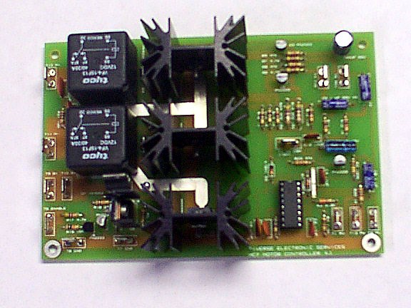
If the pins on the motor controller have labels it would be very helpful, even a good quality close up photo of the board would help.
Rich, i remember from when i used it a couple years ago, it IS an MC7 controller. I also seem to remember it is PWM. that being said i have yet to find any documentation on it. Ill keep looking. ( i have a box of papers buried somewhere that may hold promise).
The board has an additional (smaller) board attached to it on the right side (referencing the picture above). The smaller board has four connection points on it labeled gnd, ch1, ch2, bat. I currently have it conected to gnd, 12volts to 'bat' and EZB D1 to the 'ch1' input.
I will work on getting a quality photograph of it as soon as i have a moment (it is now in a -less than optimal location to do so...)
Thanks,
Gwen (hopeful)
Hope you got some good sleep...
Here is the best picture I can get right now of the smaller board on the Diverse Electronics (MC7) controller mentioned above.
Looks like it also works in RC mode (like the sabertooth).
I haven't tried it but I'm sure I read it, in RC mode the Sabertooth works with PWM, playing around with the PWM value will vary the speed and direction of the motor. I can't promise it wont release the magic blue smoke but it may be worth a shot?
I seem to remember the smaller control board being termed 'RCIC2'
Are you suggesting to try changing the sabertooth to PWM mode and try controlling both the sabertooth and the MC7 using PWM?
If, so, what control in EZB would I use? Could it be used with the game controller (and joysticks)?
OMG, I am so far over my head here...
I do really appreciate your suggestions. I'll never hold any mysterious blue smoke against you... lol I promise. ( I can always get a new H bridge... ) Its just that darn time constraint - (Halloween that is...)
No I was suggesting leaving the sabertooth alone.
Connect, say Port D15 to CH1 of this board Add a PWM control for D15 Play with the PWM values to see which values make it turn in which direction and at what speed (if any).
Although I must stress I cannot promise it wont break the H-Bridge