rgordon
USA
Asked
— Edited
Anyone made a robot that finds its own charger and docks with it? What would be a good way to do this?
 HTTP Server
— Remote web control of ARC desktop: live screen interaction, movement control, camera list, EZ-Script/ControlCommand console with remote execution.
Try it →
HTTP Server
— Remote web control of ARC desktop: live screen interaction, movement control, camera list, EZ-Script/ControlCommand console with remote execution.
Try it →
Anyone made a robot that finds its own charger and docks with it? What would be a good way to do this?

I know the EZB can take 8.4v on the ADC without it instantly frying, I had mine hooked up to 8.4v for about half an hour before I realised what I had done so in my specific build it's not something that I feel justifies completely rewiring the power circuits. I'll take the chance that R2 wont open circuit (it's similar odds to D1 open circuiting at the same time as R2)
chances of both is almost none for both to open and at the same time,i guess you got lucky
saying always goes "better to be safe then sorry" ,but you dont have to do it ,its your board you made
Its just what good engineers do and add when they make designs to sell
Same for using 3v with a 5 volt micro and 5 volts with 3 volt micro you need a level conveter on on and current protection on another
Between this this week and next week i will be posting many circuits of home base charger designs i made and they works.
FIRST need to make a schematic using expressSCH from my paper schematic and convert to gif and then to jpeg ,all circuits wil have part #'s
Kinda hard to post links on the parts only because people live in different countries and may be they can get it there better or at radio shack (josh's hang out)
These ideas are for some to use or might see a better design or changes to to them.
Also non electronic builders i can very easy make the circuit for you free only pay for parts and postage, i must of made well over 2000 circuits so it super easy for me.
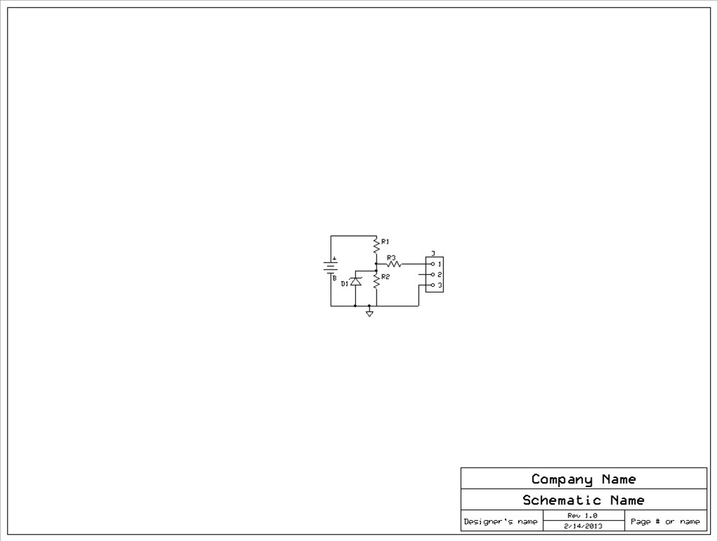
this circuit is same as RICH only added the zener diode he said to post it as a jpegD1 IS BZX79-C5V1,133 5.1 VOLTS AT 400MA any 5.1 volt zener will work THIS zener is so that the A-D will never go higher then 5.1 volts R1 is 30k 1/4 watt R2 is 10k 1/4 watt R3 is 10k 1/4 watt MAIN REASON for this one is noise and limits the current going into the A-D input
Sorry about the size next time my photos will be bigger ,I JUST MADE IT FAST
You could have just re-posted the schematic and part list I posted a few hours ago with the zener diode on it but nevermind...
yes i did in ZIP FILE not jpeg
THIS is a circuit to turn a light on in room for your robot to find it way to the charger when its dark.
here is my simple lamp circuit will post the parts list latter,i had to make 2 custom componets ,since not in the library
Resistor R is 47 ohms and line one goes to lamp on one side. line 2 can be hot or neutral and lamp the other
on optocoupler is MOC3011 AND TRAIC is 2N6342 ,but depends on the lamp uses
futurec in UK is great place to buy parts one of my favorate places ,mostly very low cost.
I might be missing something but what does that circuit do and how is it relevant to this topic?
And I was refering to the schematic I posted on page 13, the one immediately before the script... since the parts list and schematic is identical to the one you posted (page 14 post 8) was there really any need to re-post it at a lesser quality image and without values and part numbers on the actual schematic? It just buries the good posts under a load of rubbish.
Top of the next page so this is as good a place as any to recap...
Summary of previously discussed issues that must be solved:
I think that's about where we have got to at the moment isn't it? Let me know if any additional notes need adding or any posts need directing to for any of the points (page number, post number) and I will add it in.
It does alot ,i guess you forgot about the idea to use EZB to turn on lights for using QR codes or other tracking,but i guess you have bad memory
This circuit is not really for you RICH'
Just post for others you might want it.
like i always say you love to pick on only me on any topic