Adrien
Hey all,
I've been experimenting with the EZB for a few days now, and I would like to start recording some data via the analog ports! I don't think I've got a problem wih the code part, but I'm stuck with an electronics problem :
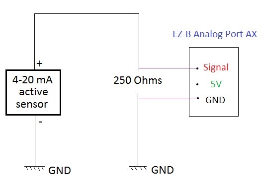
I have a sensor that provides me with a 4-20mA analogic feedback at 15V. I used a 250 Ohms resistance in series with that in order to transfer the information from the current to the voltage drop in the resistance, and to limit the voltage drop to 5V within the resistance. I know I'm probably going to lose precision turning a 16mA-width measurement range into a 4V one, but I'm just trying to play around to get used to the basics. This works fine with a voltmeter, but it doesn't work when I plug that into one of the analog ports of the EZ-B : I get 0V readings all the time!
Is it because of the internal impedance of the analog input circuit? Or is it a beginner's mistake in the wiring? Or both? I'm sorry about my low skills in electronics, it's been awhile! I included a couple of pictures to show you the wiring I made. Thanks for your help!


Is it a common ground or are the grounds separate? It needs to be common.
If 5V is applied to the Signal pin of any ADC port then reading the ADC value will return 255, make sure you have it going to the Signal pin.
I've always used voltage dividers when I have something that has a voltage above 5v and have had no problems. Just double check the wiring and check that the voltage going to the signal is <5v
Hello,
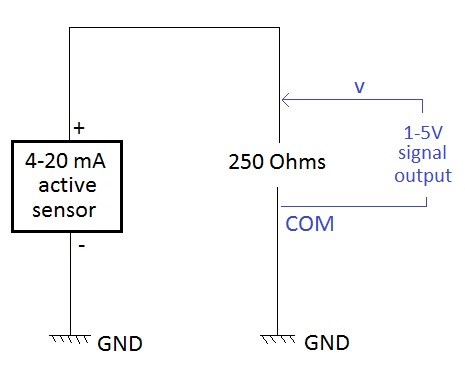
Yep it is a common ground (sorry for the confusing sketch!) and I'm sure I'm going to the signal pin. When I load my sensor, the current goes up to 20mA and the voltage at the resistance becomes 5V. So far so good. When I plug the EZ-b in derivation (as a voltmeter), it affects the sensor in a significant way :
And these tests were performed without the power supply to the Ez-B. When I turn on the EZ-B, the 0.67V value goes down to stabilize at 0.64V. Then, if I turn the EZ-B power supply off, the voltage drops to 0.59V and then comes back after 10-20s at 0.67V Do you think this reaction is linked to an unexpected behavior of my sensor? FYI, it is a weighing scale with an analog output extracted from an RS232 interface (2 of the wires are taken out, one (-) is ground and the other (+) is the signal)
Let me know if you have any suggestions, or if you need me to do some specific tests. This is what I've been doing in terms of wiring :
Thanks for the help!
If I'm not mistaken you also need a resistor on the Signal pin of the EZ-B.
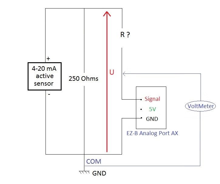
Why do I need a resistor there? Given that the voltage I get is th one I want? If I put a resistor R on the signal pin, then the read voltage should be : U*R/(R+R_EZB_AnalogPort) right? But I can't evaluate the resistance of the EZ_B, it looks like it is to be considerated infinite.. I must be wrong!
Are you implying this kind of configuration?

I don't know how to choose R given that the 250 Ohms resistor is already giving me a voltage U between 1 and 5 V Should I change it to be between 1 and say 10V so that the voltage drop via R gives me a Signal voltage up to 5V max?I tried to boost it up but the U voltage doesn't go higher than 0.72V with an empty load. However if I open the circuit where the EZ_b is (I now only have a resistor in parrallel with the sensor), I can get as much as 15V again.
Thanks for your help See you tomorrow!
To be honest I'm not sure, I just recall something about a pull up/pull down resistor to stop it "floating". It may not be required in this case but I know it was the solution to other issues with the ADC ports. I'm sure if you search the forum for the term pull up resistor or even floating it will come up with posts regarding them (they are on here somewhere since this is where I would have read it).
Is there a reason you are against using a voltage divider to drop the voltage down to a third (15V down to 5V)? You can then multiply it by 3 in ARC to get the correct value.
I have a small photo/light sensor that came with the getting started with arduino kit and I had to use a resistor to get it to actually read a value other than 255. With both boards. After I did most of it with the arduino I went and figured out how to do it with the EZB. I do not know why this is. I'm very new to electronics and still kind of struggle with some of it. But, I can, from experience 2nd the motion of using a resistor on the signal wire.
Hey all,
Thanks for yours comments!
I've been browsing the forum, learning about the use of pullUp/pulldown resistors, but I don't think that has something to do with my problem. If I'm not wrong, it is to avoid static feedback, but given that my sensor is not a passive one, I think I'm good.
I'm not against using a voltage divider, but this is what I thought I was doing by using the 250 Ohms resistance :-), Are you implying to use just one resistor in series with the signal? I'm curious to know!
My goal with the 250 Ohms in parrallel was not only to drop the voltage but also to turn the 4-20mA signal into a variable 1-5V one. And guess what, I could get correct readings when I turned around the GND and signal pin on the EZ_B. Assuming the ground on the EZ_B is correct, it looks like I misread the RS232 cables and switched the + with the - !
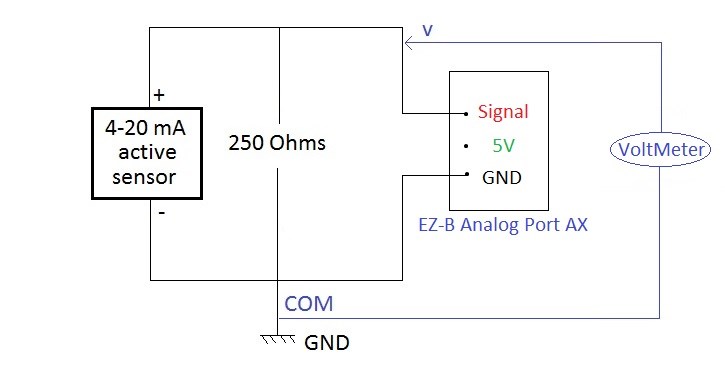
Now, using this wiring

, I finally get what I want! I've been able to record a varying load on the weighing scale, from 1V (empty load) up to 5V (full load), sooo thanks for your help (You were right Rich, I needed a double check on the wiring!). However, I find it strange that when the EZB is not turned on, the full load gives me a 3V reading, but when it's turned on, it goes up to 5V.See you around :-)
Adrien