
mdeming1
Wheel Spec Clarification Needed
Hi all I'm happy to say I finally finished my robot chassis such as it is this weekend. When I make a more square version I'm going to use the suggestions given in my earlier frame post but I figured I'd already hacked up enough aluminum to keep cocola afloat for a year so I may as well use it.
Anyway, I've had a wheel fitment problem from the start, I think I have a solution so I'll post it and would like to know if the solution will work. ( please forgive my mixture of standard and metric references in advance, I don't have as many metric measuring devices as I'd like to)
I have two jazzy 600xl motors. The motors have a 17mm dia keyed shaft (6mmx40mm keyway), the motor shaft is 1-7/8" to the beginning of the thread and 2-3/8" to the end of the thread, thread is M10x1.25
The original wheels are 13" diameter and far too large for my project (I wish I'd have realized that before I bought them). I just need a cheap 10" or so lawn wheel. Most lawn wheels in the states have a bearing bore diameter of either 5/8" (too small) or 3/4" (too large). My first thought was to buy 3/4" bearings and an adapter for a 17mm bore, a guy sells these adapters on eBay for like $12. The problem is that nothing would stop the bearing from spinning and the wheel not moving.
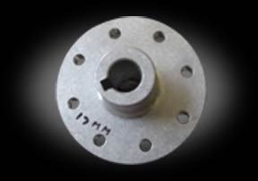
So I kept looking and found these:
A 17mm hub with a 6mm keyed bore.
I figured I could get them to bolt on to these wheels:
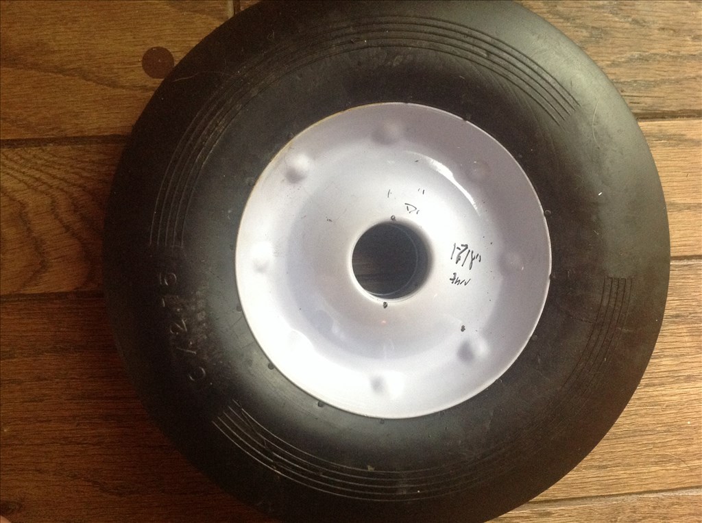
They are 10x2.75" wheels with a through hub diameter of 1 7/8" and a bearing hole diameter of 1 3/8"
Do you think I'd still need a bearing or would you just bolt this hub on to the wheel, attach it and go?
The answer is probably staring me in the face but I've been looking for a solution for so long I can't see the forest for the trees anymore. All assistance appreciated.
Matt

Just for the fun of it I did a little CAD drawing of your parts using a combination of sizes from the linked site for the hub and basically re-sizing on the screen and measuring. Here is the hub (blue) laid over the wheel (red). It looks like if you centre the hub on the wheel, there should be enough material to bolt through and not use the bearing. Just my thoughts.
Also for anyone out there who would like to know a metric to imperial conversion trick on a calculator with a tax- and tax+ button, set the tax as 2440. When you have a measurement in inches, hit the tax+ for millimeters, and tax- for millimeters to inches.
Hi Steve Thank you, you can't realize how much this wheel issue has been a thorn in my side. I never thought it would be such a challenge to find wheels to fit the motors.
I do have a clarification question. Does the hub negate the need for a bearing? I mean this isn't going to be a car or something that goes hundreds of miles at constant high rpms, but the bearing v hub use is just confusing to me. By the way, the wheel I show originally had a 5/8"id bearing (1-3/8" od) and I drove it out.
I'm guessing that the precision required to mount the hub is going to be a little more than my hand drill is going to provide right?
Also, a tongue in cheek quote from a tv show "Archer" regarding metric/standard:
Malory: Who uses the metric system? Lana: Everyone except us, Libya, and Burma. Sterling: Really? Because you never think of those other two as having their s*** together.?
;)
Where did you get the designing program to design that wheel can you please send me a link
@mdeming1 - I guess I should ask you for more information. What were you looking at for a layout of the wheels and drives? Are you doing two drive wheels with casters or four 10" wheels (either two wheel drive or four?) Other things for me to know would be are you planning direct drive or some sort of belt/chain drive? If you could draw out a small diagram of your proposed layout I could help with ideas and workings, like a second pair of eyes. This will help answer your questions about bearings or no bearings. The reason I jumped on helping you was because I have four 10" wheels and some steel square tubing to make my big robot out of. I was in a similar place not knowing how to connect my drive. I have bearings in my wheels but I plan on either a belt drive or chain drive, therefore the bearings (which actually don't work too well... that's why they were only $6 ea.) are being used to mount the wheels on a bolt. I plan on mounting a pulley or a sprocket to the hub of the caster and run four wheel drive. I have a few different motor combinations that I might use if I can't get my hands on a pair of wheelchair motors. I still have to iron out that end of things yet. This is one of my wheels. I like them because of the long hub and the fact that if I want I can take it off and bolt on something different.
So if you can pencil sketch or even just lay out some of your parts to show your proposed ideas I can see the direction you're heading. I guess I just took a guess that you were direct mounting the wheels to the motor, then the bearings are not needed, but if there is a different plan then that might need to change.
@Mohamed.r - I used AutoCAD 2005 for the diagram. This program is quite expensive to get, but there are lots of free design software on the internet like SketchUp and 123D Design. These have been mentioned in other posts.
Hi Steve I'll try to draft and scan a decent sketch in the morning. For right now just imagine a two wheel direct drive system with a front free caster. As I said, this is a utility rover not a race car so I think/hope your original answer may still apply. The thing that has been the biggest challenge has been the length of the motor shaft coupled with it's diameter. Either the wheel hubs were too thick for the shaft, or on wheels that fit, the bearing diameter would be too small and then add to that the key way shaft. These hubs are about the only thing I've found that will work. I don't mind taking them to a shop with a drill press if needed.
I appreciate everything and I'll get some better specs and a drawing in the morning.
regards Matt
@mdening1 - Going by the specs. in the review/comments (second comment give a lot of measurements), the hub is 1 3/4" thick over all, making it 1/8" shorter then the pre-thread part of the motor shaft. Is there a tab or anything that would stop the hub from bottoming out on the shaft against the motor? I think these hubs are what you need according to a pair of motors I found on Ebay using the model you gave. At the motor end of the shaft it shows a lip to keep the hub off the motor face. Are yours like that and is that lip part of the 1 7/8"? Even if needed, a doubled up washer will take up the 1/8" difference.
And here is a cheesy "Paint" diagram of the mounting of the hub to the wheel.
Hope this helps a little bit more.
Hi Steve Sorry for not getting back yesterday. I didn't have as much time as I thought I'd have and most of the free time I had was spent having to edit an instructable for a gadget hack I made to enter a contest on that site.
First, let me say your cheesy diagram makes me pumped up to get these hubs and put them on my wheels!
I went out and measured (this is a generous definition of my efforts) the lip and shaft again. My 1-7/8 is with the ruler setting on the lip. The lip appears to be about 1/8". Again, my measuring tools and skills are SORELY lacking.
I recollect receiving some extra parts with the motors, there may have been some spacers but regardless of if there were or not, I'm pretty sure that if there is an issue the washer idea will work. Conversely, if spacing is off in the other direction, I can use a nut with a smaller thickness than the current one.
I hope my hubs and encoders arrive soon. I'm ready to get them on. I'll send a photo when they arrive.
Thank you again. Matt
@mdeming1 - No problem. I know how busy things can get. I'm sure once the parts arrive it will all come together... if not get a bigger hammer.