
L298n H-Bridge Heads-Up
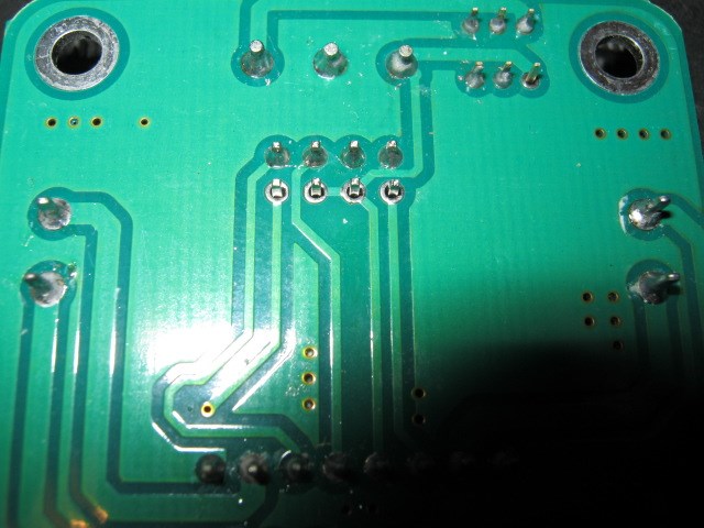
Finally got around to using the 2.5 amp H-bridge that I had purchased from the EZ-Store many moons ago. After reading through Rich's tutorial about hooking the little guy up I thought I had a pretty good handle on the process. After wiring everything up and adding the H-bridge with PWM control to my EZ-B page I could not get either of the two dc motors to run in either direction. After many hours of dis-assembly and troubleshooting the solution was finally discovered. It seems that the pins used to connect the two PWM signals from the EZ-Board to the H-bridge had never been soldered onto the PCB of the H-bridge. I hope this helps others with H-bridge issues when you run into a wall. Included is a picture that shows the 4 pins on the second row that were installed onto the PCB but never soldered that prevented the PWM signals from being received from the EZ-B.

Hah, how about that! Simple human error. I guess when your standing there soldering and pumping out bushel baskets of these a day your bound to miss something. Looks like there is another pin missing solder in the upper right hand area of the board. It's the third pin on the right on the second row down from the in the top right corner. Hope you soldered that one also and gave the rest of the board a good look over. Better reflow all the joints while your at it. The big one just right of center at the top looks kind of cold. Must have been Miller Time.
Lol, that board must have been the last on the assembly line when the whistle blew ! Lots of touch-up work on the underside of the board got it back to working order instead of the junk bin.
You may have just saved me hours of frustration. Mine wasn't as bad as yours, but one pin had a really sloppy solder connection on it which I will clean up before trying to use the board.
Alan