
rgadagno
H-Bridge Dual Dc Motor Controller
Hi, I picked one of these of eBay while i am waiting for the 2.5 amp controller from the store. I was able to get it to work. It move forward backward and both left and right. It would not stop with the with the HBridge control. The control would allow me to change directions. I added a PWM control which i could make it move and stop and different speeds. I added the voice command and noticed when i said stop the robot would turn. Anyway i was just playing with it moving around the room and it just stop. It looks like one of the digital ports stop working. Verified by attaching a server to it. Before i do anything else i want to double check my setup.
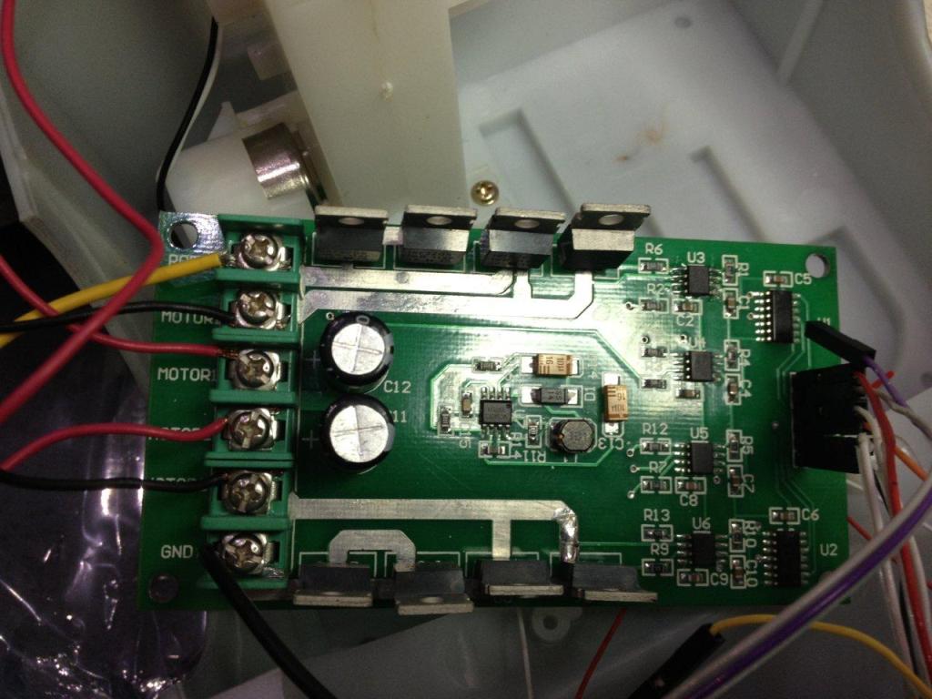
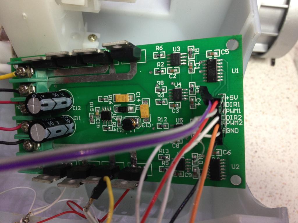
On the attached picture i have +5 to +5 on the board have the gnd to gnd on the board. The DIR1 I have it going to d16 the DIR2 going to D17 I have both PWM1 and PWM2 tied together and set to D1. Which wen i move the slider it would speed up and down and when i clicked stop it would stop.
Question DIR1 stand for? Question on the H bridge controller I was only using Left TriggerA(D16) and B(17). What is the Right trigger A and B for. What do they mean in terms of controls to the motors? Since i did blow out D15 i want to make sure what i doing is right.
If i wanted to fix the D15 what would i need to change on the board?

I found a little bit more info. Control signal:
motor corotation: DIR=1 PWM=PWM motor inversion: DIR=0 PWM=PWM stop and brake: DIR=X PWM =0
So i take it that DIR is direction. If they take a PWM signal it look like i would only need 2 digital ports to control it? So how would this relate to the H bridge controller? Left TriggerA ? TriggerB?
I have it working for the most part. I have a video of the setup and the robot moving. The configuration is set as Left Trigger A = D3 Left Trigger B = D4 Right Trigger A = D4 Right Trigger B = D4 I have the PWM on D2 and both pwm on the H-bridge is tied together. I have one DIR1 to D3 and the other DIR2 on the H-bridge to D4. Here is a video of it.
I dont understand when i hit stop on the control that it spins.