


hi all
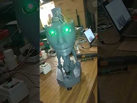
I've created a modified version of the EZ Robot head, featuring both side-to-side and up-and-down (yes) movements. This new design includes an improved base for the head, accommodating three additional HDD servos. There's an option to install two cameras, with the base designed to allow passage for a second camera cable. This setup is ideal for incorporating additional IoT devices or EZBV4, for instance, for LED lighting. Conveniently, there's no need to remove the potentiometer from a servo, as the 1 to 180-degree range provides ample movement. The base height is 7.2 cm.
The pistons are original components from InMoov, and the neck base in EZ Robot is correctly designed.
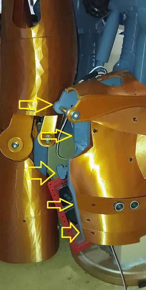
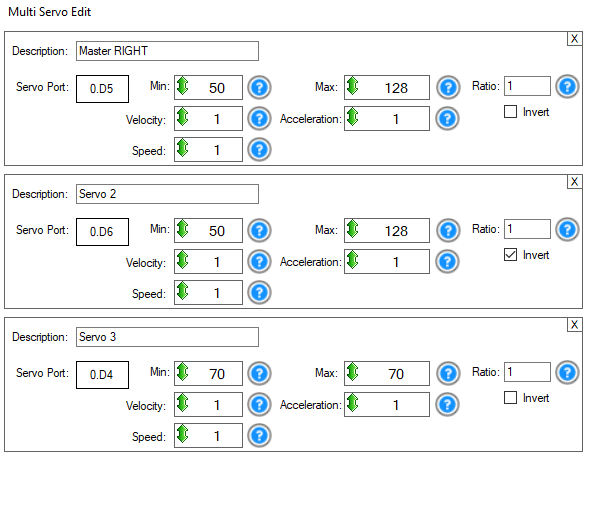
For moving the side pistons, adhere to these settings:
Programming
Adjusting the side pistons can be a bit complex. Start by calibrating your HDD servos. Then, align the inner piston with the holes in the piston base and secure it with a screw. For the second side piston, align it similarly, then disconnect the IoTiny. This allows you to manually adjust the previous piston to properly position the second one. The original documentation on EZ Robot is extremely helpful in this process.
Parts & Materials
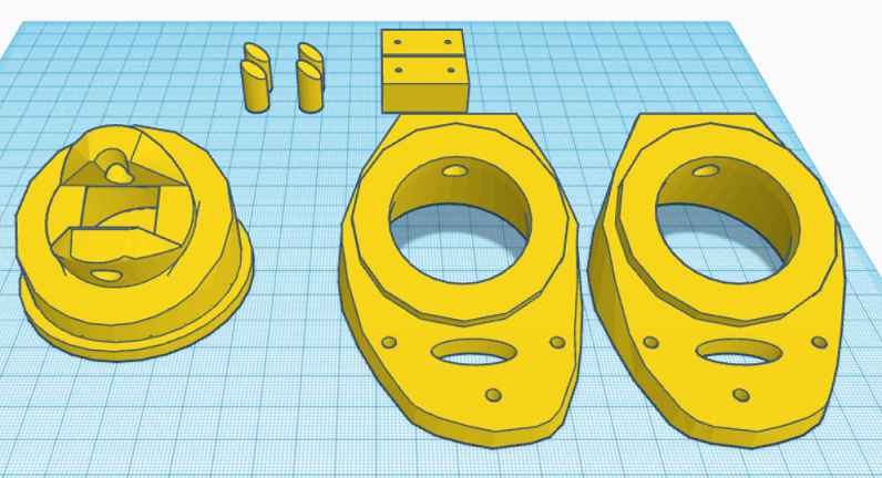
You'll need 3 extra HDD servos and grey PLA filament. The drive shaft parts should be printed with a 35% infill and a gyroid pattern in your slicer for enhanced strength. Other parts can be printed according to your preferences. Additionally, there's an optional neck extension, offering one to three extra vertebrae for more piston movement space. In my experience, the two-vertebrae option works best.
Other robots from Synthiam community
Ezang's Robot Hand / Fingers 1/5/2020
Faengelm's Rider The Ball Kicker Servo Port Numbers

hi all
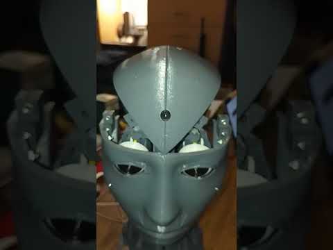
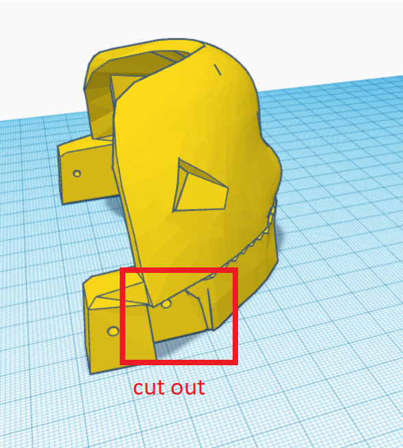
i notest that the mouth not fully closed . i made some mods .
jaw has a cut out and also the jaw hinges are modiefied .
new folder sendfolder.zip
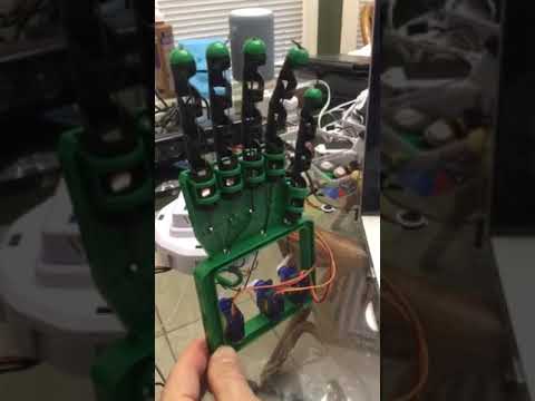
little video of the jaw problem .
Great work nomad! Looks like you spent a lot of time on it with good success! Thanks for sharing. Looking forward to seeing what you do next
@dj
tomorow printing the new jaw and testing . then its just finishing the head .
do it all over for my full inmoove robot .
thanks for the kind words .
hi all
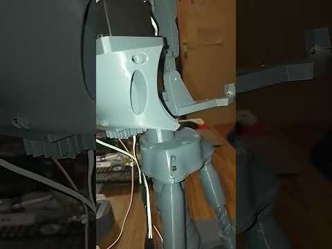
i made a new base if you want only the yes motion . so you need only one working piston .and two springloade hollow pistons .
only yes base.stl
hi all
i made hollow springloaded pistons for the only yes base . this to keep the head level . on the left side picture . the two , small pieces wil be moveble to get inline with the neck base , were the tree pistons are housing . video soon .
Commenting to follow progress!
Nice work Nomad. I am wondering how to move forward. Do I do this mod and if so will it align with actual inmoov? What is Jeremie working on? Will I head in one direction and then have to change to another. I think I may as well go forward and build the entire Inmoov (I put filament on my Christmas list) but I would like to have something that is at least loosely supported and a roadmap. InMoov changed direction and primarily uses MRL but its a terrible platform to work with so I don’t want to go down that path. If I wanted pain in my life I would use ROS.
hi nink
i will test the new mouth in a few houres . then i can post a video so you can see the improment there . a complete inmoove is allot of work . there are so many files old and new together . its easy to print , the wrong parts . personally i find the arms to most diff to do . i didn started that part yet .
thanks
hi averyone
so tested the mouth and still needed a little adjustment . so here's the new perfect jaw and hinges folder . the mouth close very good .
latestjawMod.zip
I wouldn’t consider using absolutely anything else after you see what the next ARC version is like pretty sure we’re gonna blow your minds.
so yah - make that inmoov cause we still need a bit more time. I was hoping for new year but we’re probably a month or two out. Big job is porting all the 700 robot skills to the new software. And new website and etc etc. stay tuned
@dj
wow 700 robot skills . thats enough till am 100 years old . new website . cool am alreddy in chrismas mood .;)
@Nink I can't share what I'm working on yet I wish I could!
hi averyone
i hearded this line before but cant remember were .xD steve is not finisched but stil have its own mind . cool
hi averyone
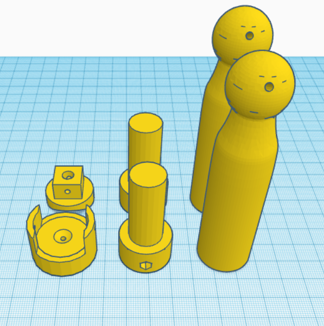
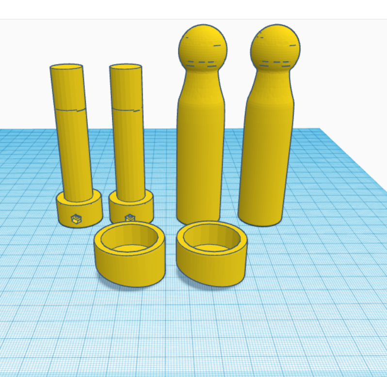
for the base with no side movement . i made a springpiston model . the springloaded base looks same as the one with ,only two servo's less needed .
to keep the pistons in place on the base i use piston cups . the cups lean towarts the upper hollow pistons . spring size 80 mm 1.5 wire thikness medium soft spring .
cup and hollow pistons .
hollow pistons.zip
more to come .testing new head frame .
Great work! You're really enjoying remixing the InMoov head! Are you considering making the entire InMoov someday too?
@dj
i have allreddy allot of parts for the compleet inmoove . the full front&back pannels . the neck + pistons .all in copper color . i have some rest now doing less stressfull things .xD i like tinkering stuf .
thank you
hi
first part is in place . can you see what i changed ?
hi
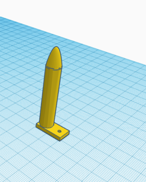
made a simpel tool to dril your tiny holes in the right place . using a bad servo or older one .
https://www.youtube.com/shorts/8G8yfa1uN6s
hi
i'm making two inmoove heads . one with the cam in the left eye , and one with the cam in center .
hi all
i adjusted the files for the camera in the front of the head . i use some hot glue to keep the cable and cam in place . its a long print but it looks great .
frontcamera.stl
Nomad I am really enjoying watching the progress on your build. I look forward to future updates and seeing the finished project. Thanks for sharing. .
hi nink
i'm printing the new base for it . all parts are adjusted and modified . i post the folder and video later .
thanks for following along .
hi averyone
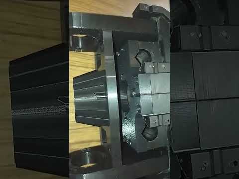
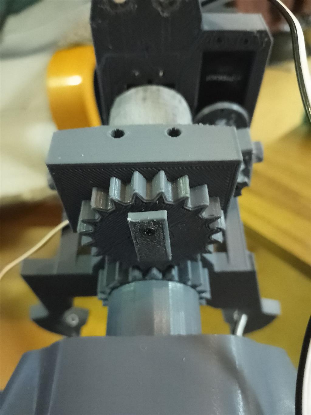
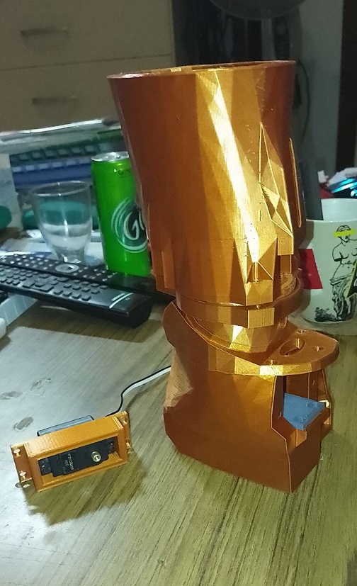
the springloaded head is reddy . only needed one extra servo for the yes motion . the base takes about 2 days to print . modified parts are . the mouth , mouth hinges , lowerbackskull , front top head for the camera to fit ,longer neck ,side inner pistons . headframe .more pictures to come later .averything els is original .there is also, a lockpin for the back servo for the no motion . to keep the screw in place .
lockpin inside the hole gear . it prevent from the servo screw to fall out . also you can see the 20 mm spacer below .
little video . https://www.youtube.com/watch?v=2ZVNEoLbEHw&ab_channel=EDP
and the folder springloaded head
sendFolder.zip
hi
some more pictures.
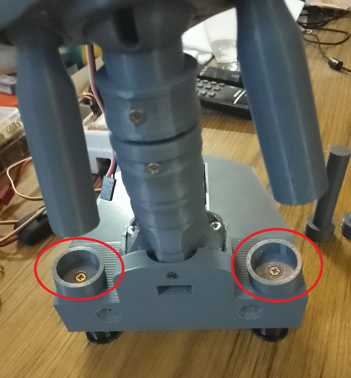
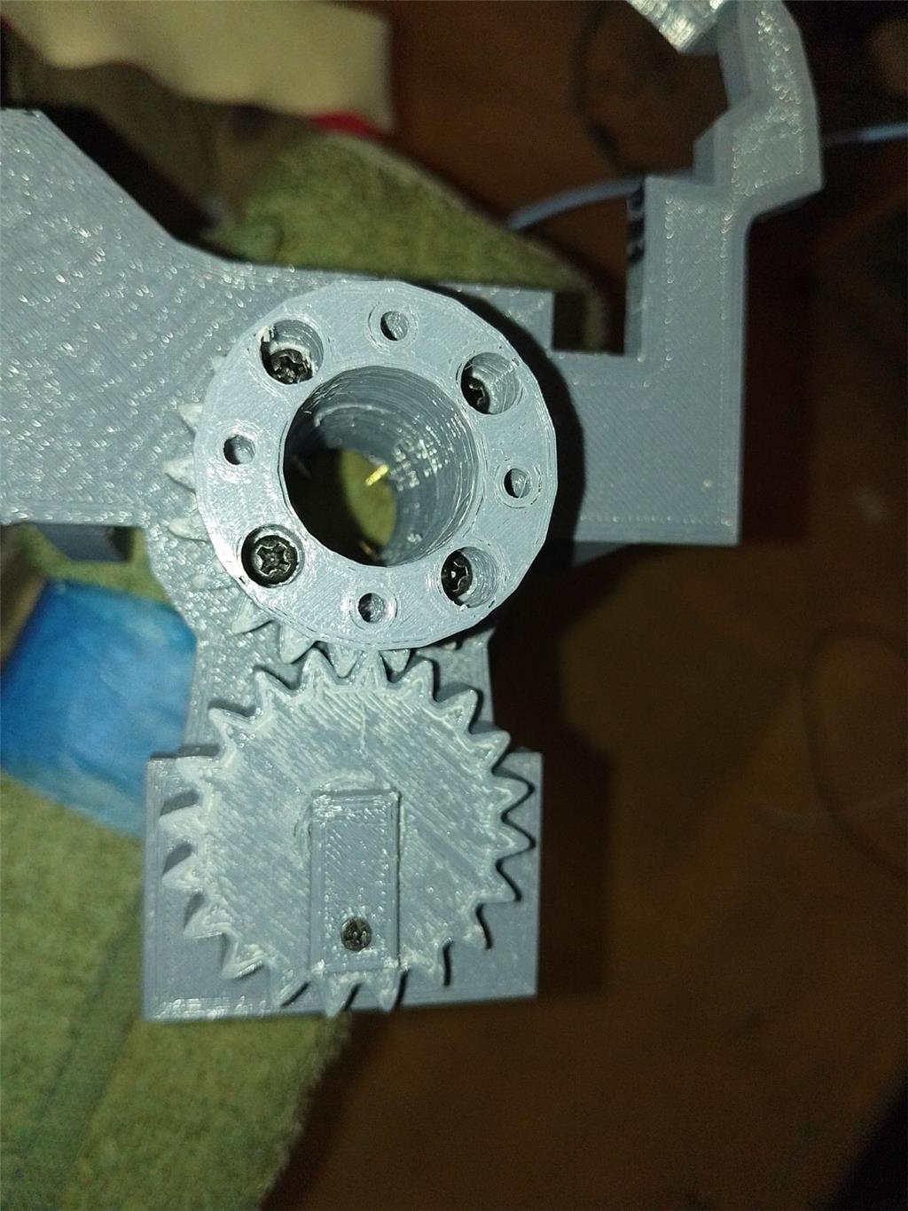
lockpin for keeping the servo screw in place so it cant fall out .
gear aline , spacer mounted.
tomorow more pictures . open neck mounted .
hi all
some random testing .
merry X-mas and happy new year soon averyone .
Merry Christmas and Happy New year to you too Nomad! Thanks for sharing your progress with us!
hi averyone
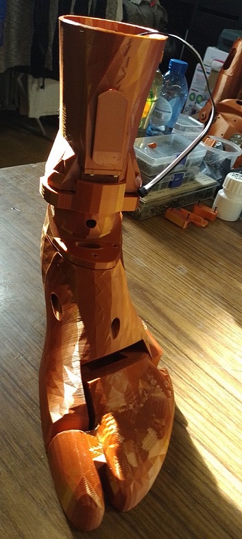
almost have one foot reddy . and the foot is going to be moveble . i post the folder later when all is bin tested . pictur is ankle leftfoot . the foot will be turnble left&right . the knees will be moveble by hand .
hi all
i notest that the ankle and hiel doesn lock . so i set my brain to thinking . and this is the solution . 4 tiny pins and a little block . the little block prevents from the pins comming out . i will test this ,when reddy i post the folder here .
https://www.youtube.com/shorts/_x5j6v0LEtk
hi averyone
left foot almost reddy for testing .
some pictures
hi
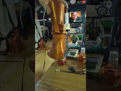
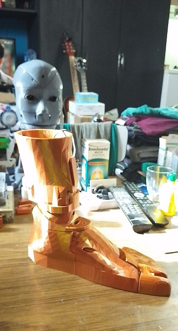
one left turneble foot reddy . the color copper is a little like glas , not so very strong as regular grey , black , green , yellow PLA . copper is good for excample outher body parts , not the main , body parts that carry most of the weight .
little videocool
send.zip
Very smooth. So you say the copper color is not as strong as the others. Are you going to reprint this part in a stronger PLA?
hi dave
yes the copper is not so strong . its good for out side parts . i keep the foot cause it doesn need to carry a load or stand on it . so no reprint is needed . i keep the main structure of the inmoove , in grey PLA .as you can see in the picture . the main structure is grey , and ontop that is the copper .
hello averyone:D
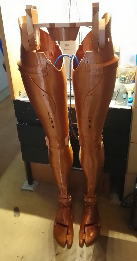
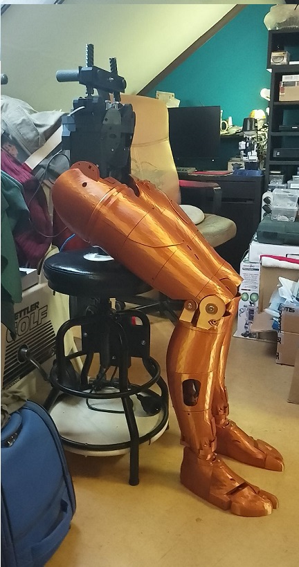
bolt legs are reddy . and they are huge .
a short video .
moving feet
Nice legs. Maybe I missed it but are you planning on trying to get these to walk of to be simply for looks?
hi dave
these are just for the looks . i gave the foot a little movement . i saw guys put the foot together whit tie wraps , this is better . the knees are bendeble by hand .
assemble video , ankle to baseplate . two pins . flat pin goes on the backside and the tapered in the front . the block in center whit two little screws .
ankle assemble
great going Nomad
Legs are what color, goldish bronze?
hi ezang
the filament is brons silk .
looks great
Hey Nomad, I got a business modem / router in my home - need my ipv4 address to connect to ARC?
or what ip should I use?
ezang
i dont have that knowledge how to do that . sorry .
thanks anyway I figured it out
hi:)
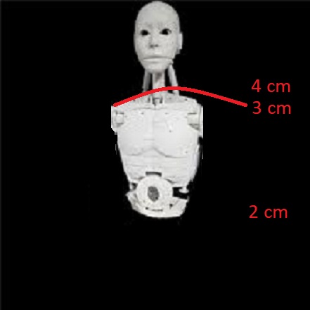
some thoughts about the right&left side ways movement . if below waist the motion is 2 cm .would that not be more shoulder hight ?
hi
back to the waist part from inmoove . doing some test . i use the HDD standard servo's . you can see how obliquely , the middle bar goes . imagine 50 cm higher .how far the schoulder , will go . i think there's no need to get the pot out . waiting for parts .
https://www.youtube.com/watch?v=1MAAEy47MIk
hi
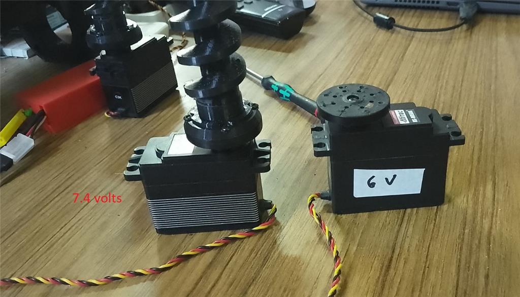
the inmoove uses the big servo HS805BB 6 volt . my question is . do i need to use the voltage regulator ?
https://www.ez-robot.com/store/p39/robot-power/inline-5v-regulator.html
hi
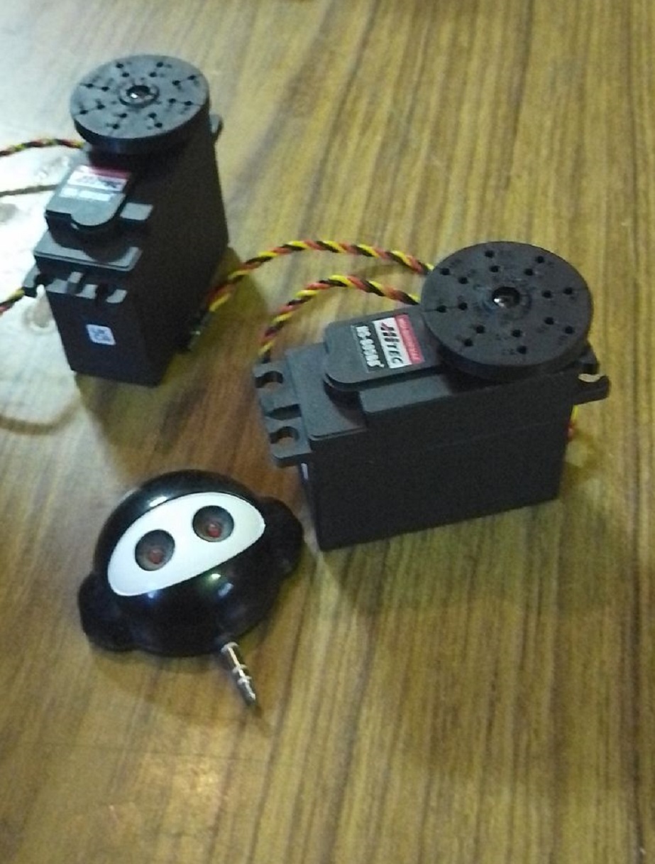
first two big servo's has arrived .
hi all
the new babies has arrived . big servo's 7.4 volts . you would think that pictures big servo's on the shop all looks desame . that the size is also desame .wel its not . they are smaller . means the place of the inmoove hip is to big . bummer . this hip part gives me all hell you can imagine .
problem solved .
Wow that is annoying. Hope your hand gets better quickly. How much torque were you trying to move. You would think they would have stall protection for that price.
nink
i used just the horizontal window . nothing connected .
Oh dear bummer. So absolutely a servo problem unless you blasted 100v through the thing. Send them hate mail and ask them to send you another one.
problem solved . servo malfunction.
EDIT: I've since learned that 3 cell LiPo Batteries are 11.1V not 7.4V. You could have a 2 cell or 4 cell 7.4V LiPo battery but not a 3 cell. Thanks guys.
I don't understand what cell number has to do with anything but I don't know a lot about batteries. I do know that when you're matching a power source like a battery to a motor or device you need to be able to supply more amps then needed (overhead) and not more volts then what the device is rated for. Also DC motors can run on a lower voltage then they are rated for (within specs). Anyway. from what I know the amperage that a battery can supply and how long they can supply it depends on the cells and how they are wired. As long as you supply the motor with enough amps and not any more voltage then needed (or way to little) you should be good to go.
Sometimes a motor in a servo will just burn up. It happens. I just had to replace a $150 HiTec servo in my robot arm. It was mounted in a servo gearbox so there wasn't a ton of torque on it. It had been running just fine for a long time until one day while moving the little motor inside just got hot, puffed up and died. Same thing happened to a different lower cost HiTec servo mounted in a different gearbox in the arm a few months ago.
After reading through a lot of RC (Airplane and car) forums on this subject saw a lot of posts that say HiTec servos can take up to 8 volts. There was also a lot of talk of servo failure rates. Some HiTec servos fail more then others. HiTec seems to discontinue thoues. My higher priced HiTec servo I mentioned above that burnt up has been discontinued.
Again, I'm no expert, just speaking from experience and what I've learned from others. Take my words with a grain of salt. LOL.
Keep up the good work and have fun!!!
2 cell is 7.4v but fully charged and put out as much as 8.3v 3 cell is 11.1v but fully charged about 12.45v.
so if you slam 12v in a servo expecting 7.4v things are going to get a little Smokey.
hi averyone
dave thank you for your opinion . it says allot .
nink
also thank you
dj looked at it and my batt was good . 2 cell 7.4 volts .
hi averyone
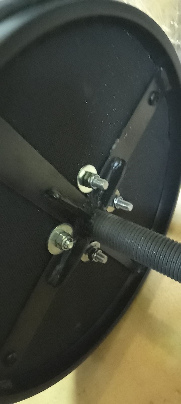
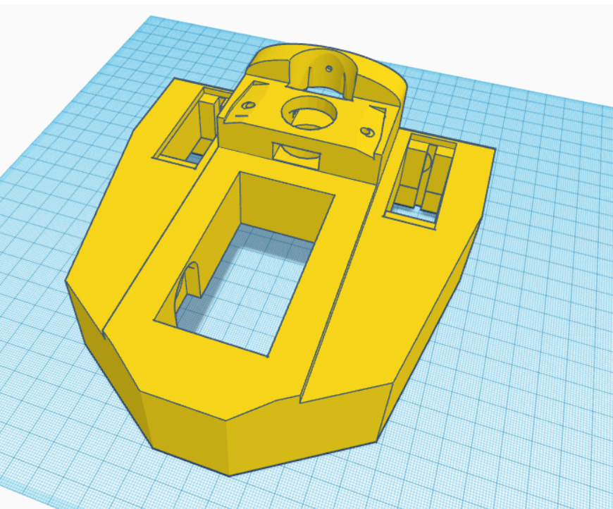
some times you have to print a part to understand why the designer made it that way . the botem plate for the inmoove butt has tapered corners . cause of the front covers . so i made that part so you can use locknut and screws M4 to make a strong bond .
a little video about that .
https://www.youtube.com/shorts/Nz96RGGmDFE
i also extended the side panels to be able to mount a metal plate ontop so the pole, you are using doesn get thru all the way to far .
baseCLOSE.stlRlongside.stlLeftlongside.stl
hi all
the final hip is reddy . longer side parts . files from post #55 here a little video how it looks .
hi
inmoove chair is almost reddy .
@Nink, thanks for the battery wisdom and keeping me honest. I learned something here.
Looking good Nomad. Pretty soon you're going to have a new friend to talk to.
hi dave
next week the legs will be on the chair .
thanks
hi all
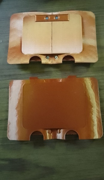
i made the backcover in one piece . no screws or nut needed . ontop foto the original two piece covers . below one piece . file below foto .
picture
backcovercomplete.stl
dave&nink
i have no idea why i freaked out but i did . i take a few days off . maybe this project is to big for me .
so my sincere appolegies to bolt of you .
No worries my friend. We all have out freak out moments. You should see some of mine.... Well, maybe you shouldn't. LOL.
Have a good week!
howdy folks
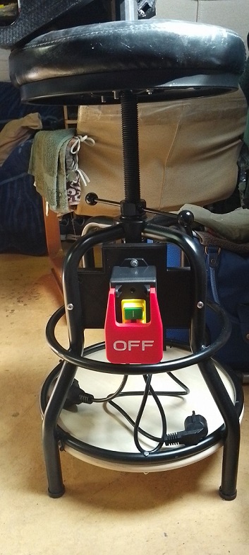
a little update on building the base chair . safety on/off switsh mounted . its a switsh that you can stop with your feet or knee when needed .
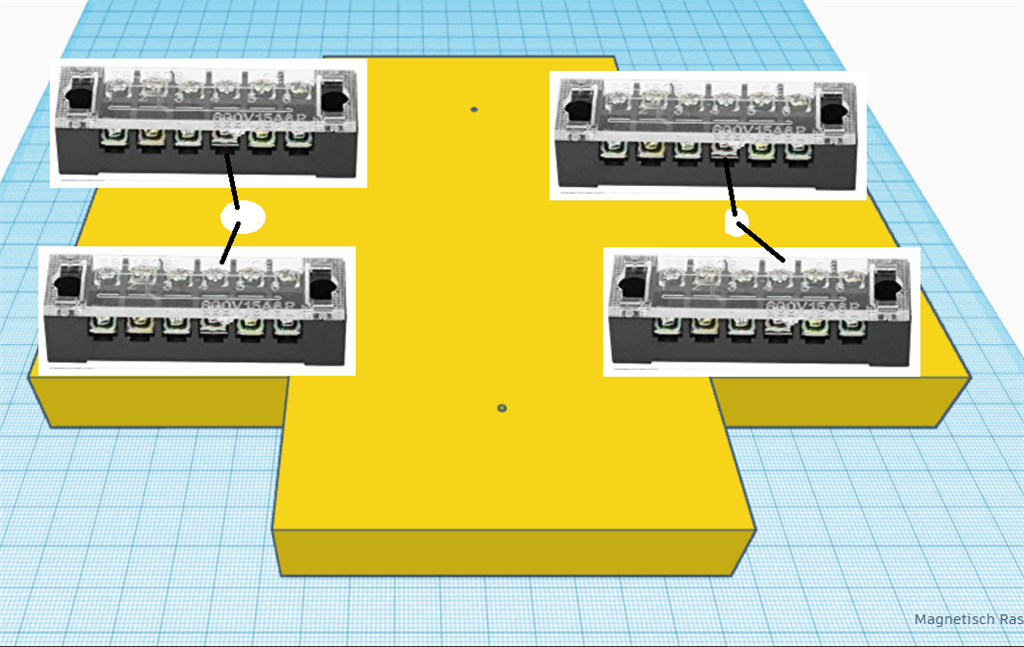
printing cross plates were i will mount the terminals .
same cross plate comes on the side were the fuse boxes will sit .
So, I'm assuming the Imoov body will be mounted on this chair? Will you be removing the seat and just be using the pipe? I've never looked closely at how you Imoov builder guys do this.
@dave
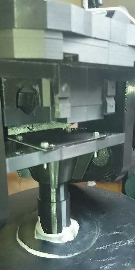
yes the inmoove wil be mounted on a metal pipe . in seat position . i mounted a metal plate so the pipe cant go further into the body .
That's really pretty cool. I'm looking forward to seeing the end result
@dave
the end result is still a long way . i will be happy if the waist wil work properly .
hi
some leg testing .
hi
the chair is adjustble in high . now the feet are on the ground .
I like the idea of the appearance of him sitting on a stool. Looks more natural.
@dave
was my idea also more natural look .
Agree also if he could ballance on stool maybe you could put servos in legs so he could move them. Cross legs etc.
hey nink
i have some movement in the feet left&right . to be able to get more movements , for excample knees hips . it will need a full re-design of the legs&hip . thats too mutch .