

cE9s4PsOgeBQIORwjd5!~~60_1-634818020230156250.jpg)


BO)Lupuc4g~~60_35-634706297915000000.jpg)
LupbT6!~~60_35-634706298769375000.jpg)


C5j!~~60_35-634655044863125000.jpg)


C5j!~~60_35-634659603510781250.jpg)


C5j!~~60_35-634651704046230469.jpg)


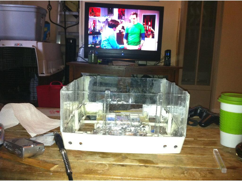


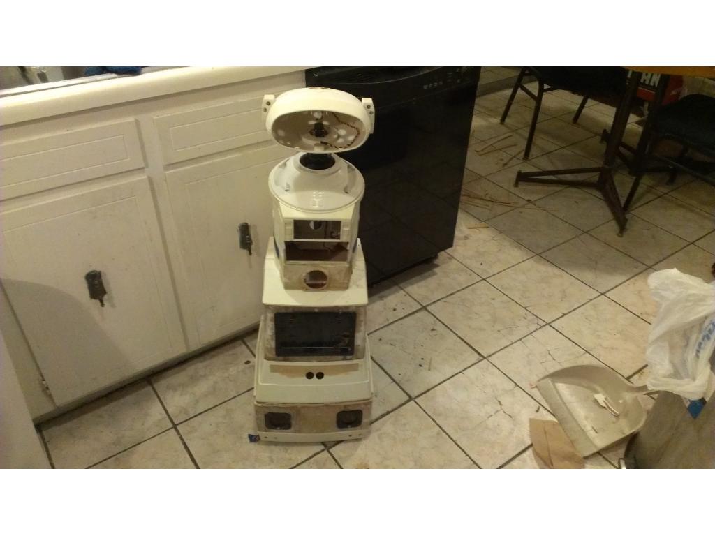

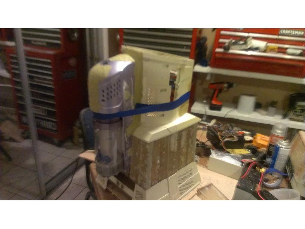


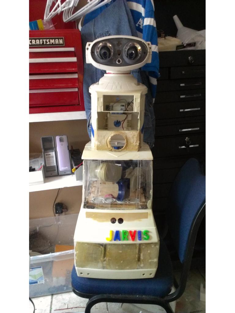
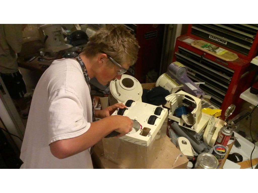


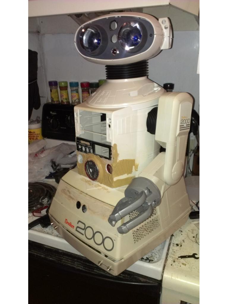


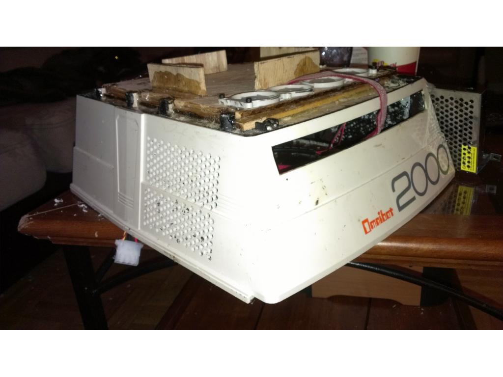

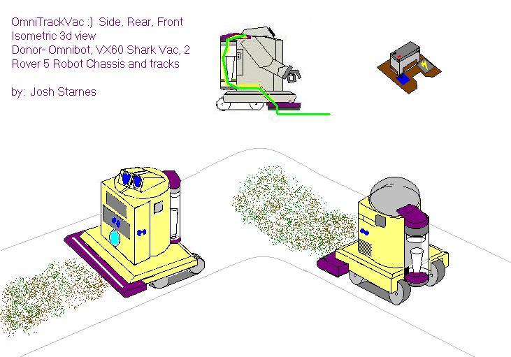


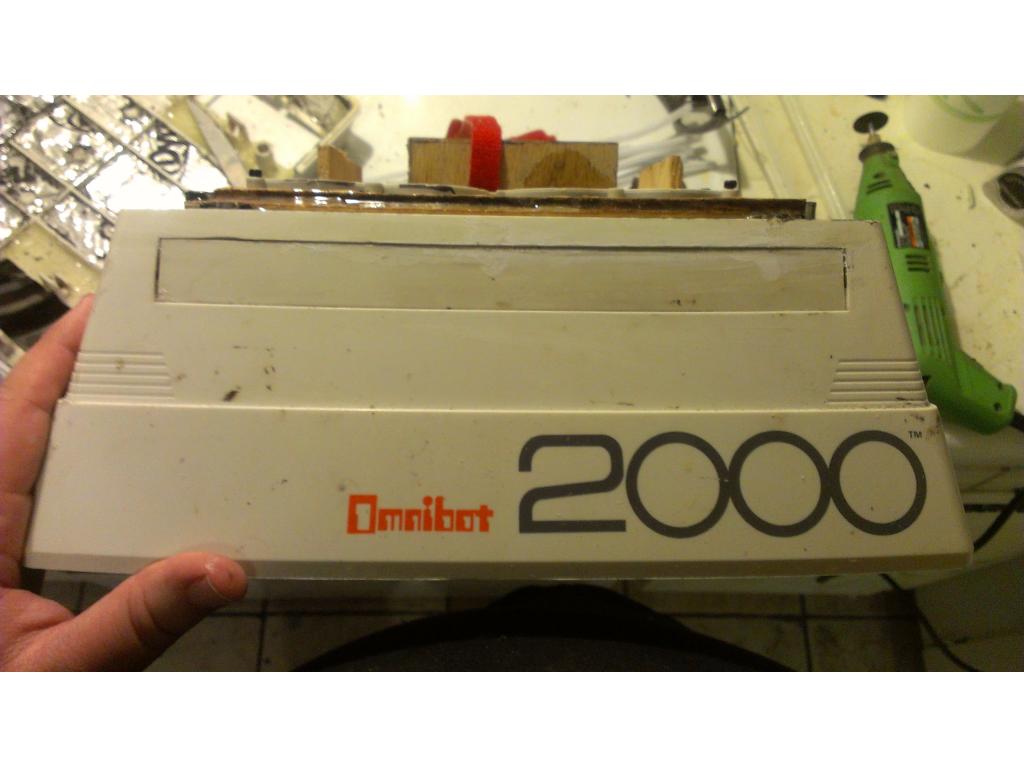
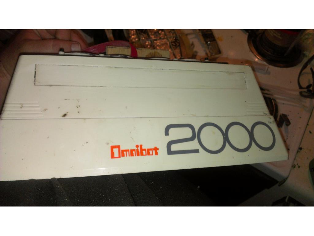


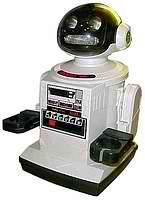
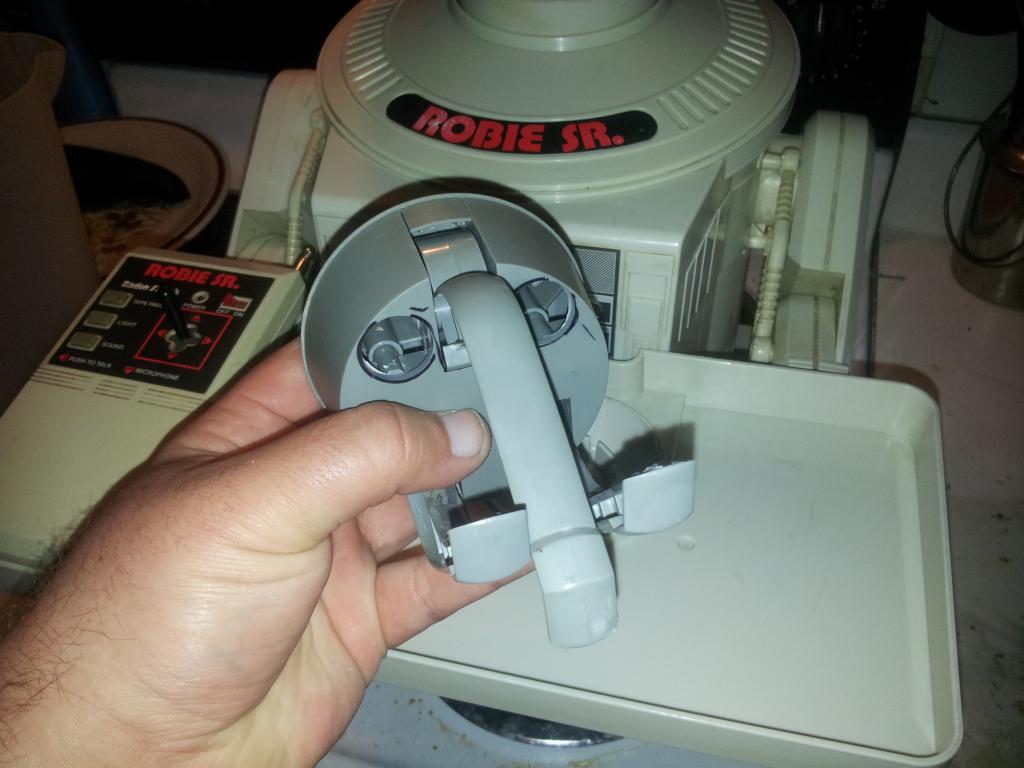
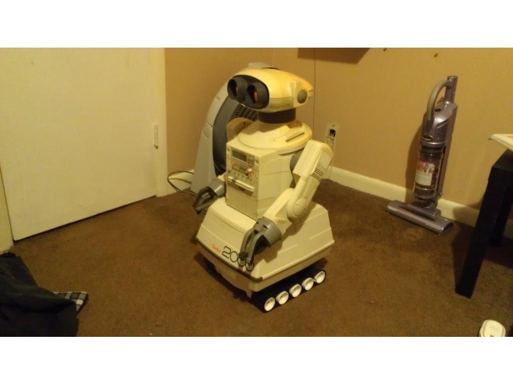
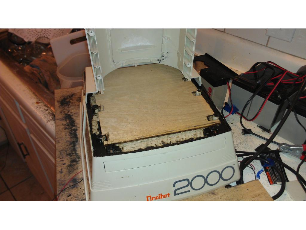
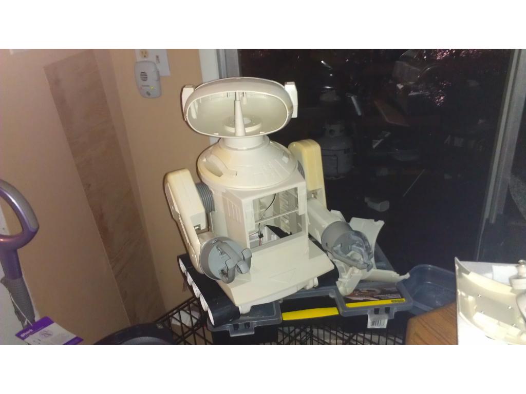
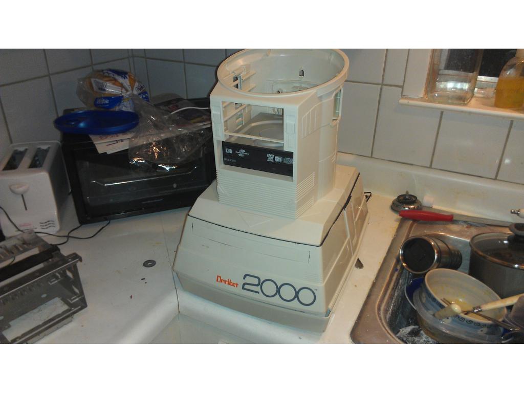
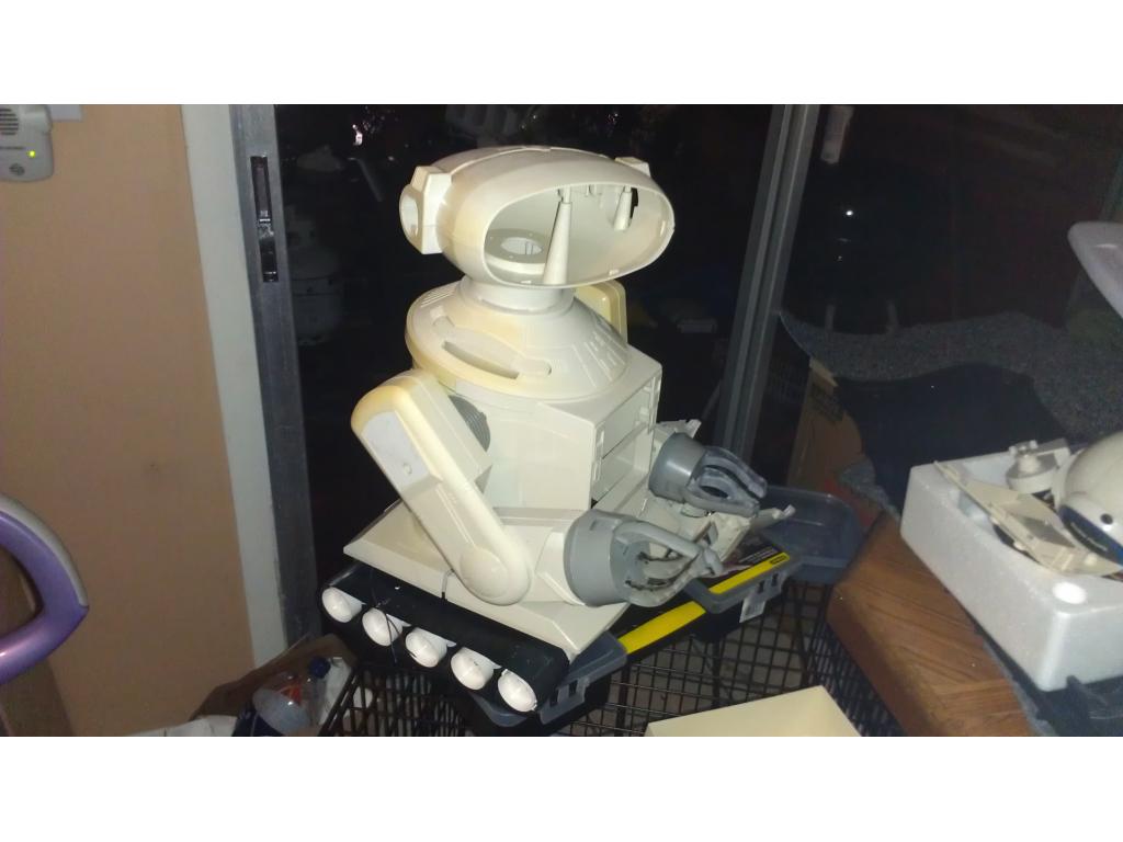
This project has evolved some , the basic rundown is I'm modding two Omnibots , one a regular the other a larger 2000 model. I will have two ezb kits , rad base idea was thrown out because of so much noise but could go back on the table if the omnibot drivetrain is too weak to pull it.

By jstarne1
— Last update
Other robots from Synthiam community
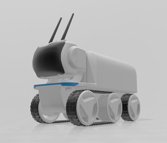
Jstarne1's Levi Rover Modular Robot 3D Print
This is the most updated model of the LEVi Platform
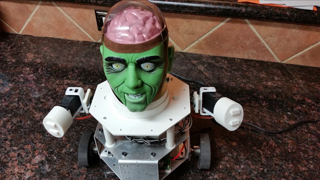
Joseph4760's Say Hello To Little Frankie
I’d like to present to the community Little Frankie. He was too scary at 7 feet tall, so I had to cut him down to about...
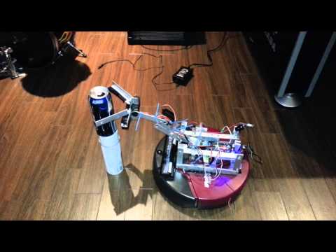
Robmcc's Brewster The Beer Buddy
First crack at my beer buddy a few more lines of code for opening the fridge adding some led light strips and good to...

I like the idea of the RAD drive section - tracks ar COOL! And it would give great traction to move that vac around. And when you are hacking a robot, nothing is sacred. I also like the idea of the canister on the back, kind of like a back pack.
Bret i really wish we talked directly back and forth , you started your omnibot project way before me so you have valued info and experience with these guys, :-) thankyou in the tracks comment , i love the agressivenesss of tracks. Ha ha i have a walle ucommand in the mail that id like to make a automated pooper scooper ha ha ha
Dude - bret.tallent@gmail.com I am in the Norfolk VA area.
What a great idea for a Wall-e!
Mines kandyred@gmail.com , im josh , im in chattanooga TN
Hey guys,
Very Jealous of your Omni 2000. Broken arm or not that will be fun!
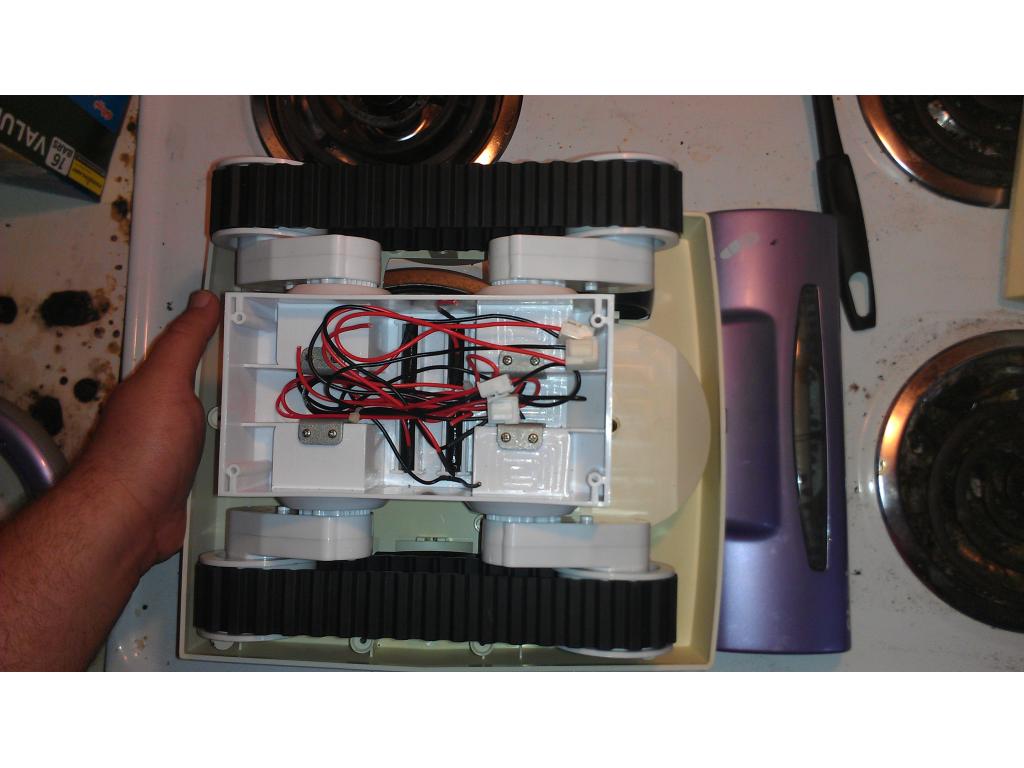
I have modded my RAD 2.0. The tracks are pretty darn powerful. I drive them with a 7.2V RC car battery. It may do fine....not sure about how it will drive the vac on heavy shag carpet. That would be an interesting test. We have a Shark Navigator vacuum too....now you got me thinking!
Below is the link to my project so far...i am still modding (Mine is going to be a Sentry Bot), but I will be watching your RAD project for sure!
btw, I am in Springfield, VA (just up the road from Bret)
Kevin
My RAD 2.0 Project
Dude! Our robots may need to meet one day lol
Lol , ez b needs a feature that let's them talk to other bots. So is your bot moving yet bret?
No, not yet.
I am waiting on a bluetooth dongle to arrive so I can't communicate with the board yet. I ordered the darn thing nearly a month ago so it should be here soon. Then I need to figure out how to wire up my h-bridge. I'll post video as I go. The first will be of the arms and claw moving.....
When we have our bots up and running, we should do a mid-atlantic region meet-up. Maybe at Oticon (big Anime convention) in Baltimore or one of the science fiction conventions in the region so we can show off a little as well as meet each other.
Alan
I like that Idea!
My inner nerds comming out ha ha ha , robots could follow us around the show .
Very cool inner nerds I think! Meeting up at some time would be awesome! Those pics with Omnibot and the vac are so cool!
Kevin
That bot is going to look uber cool!
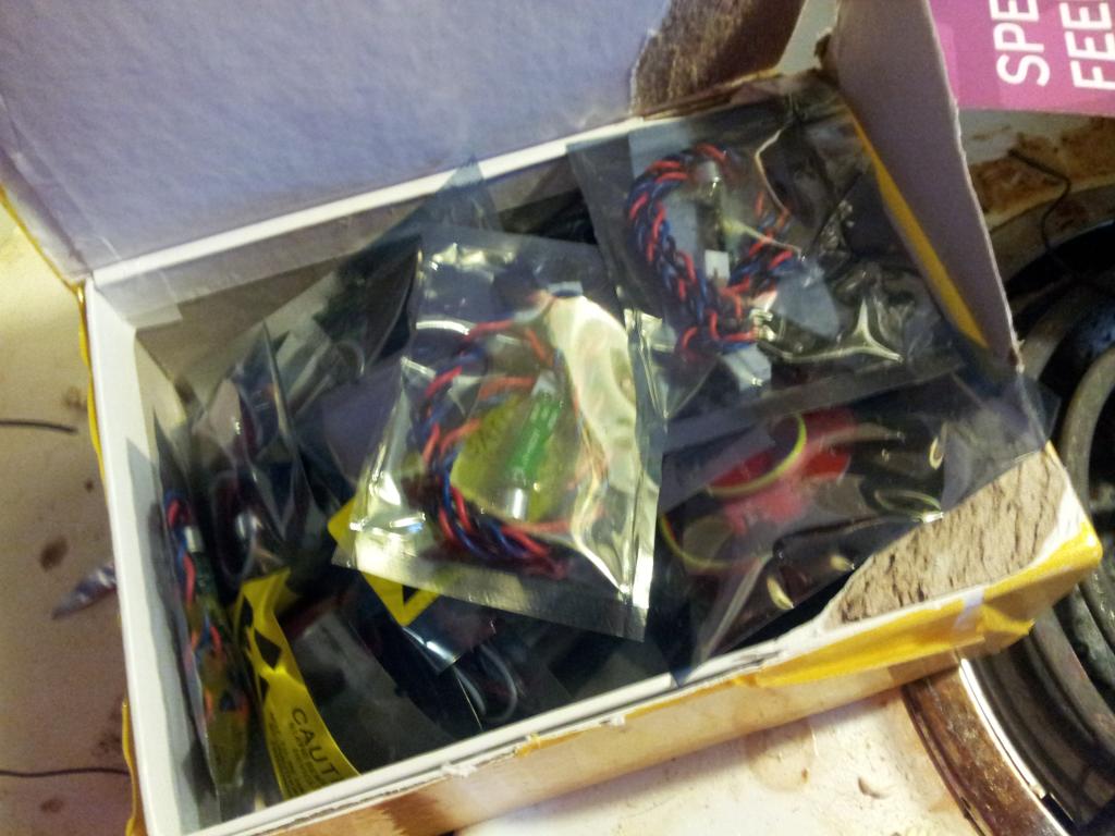
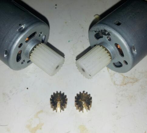
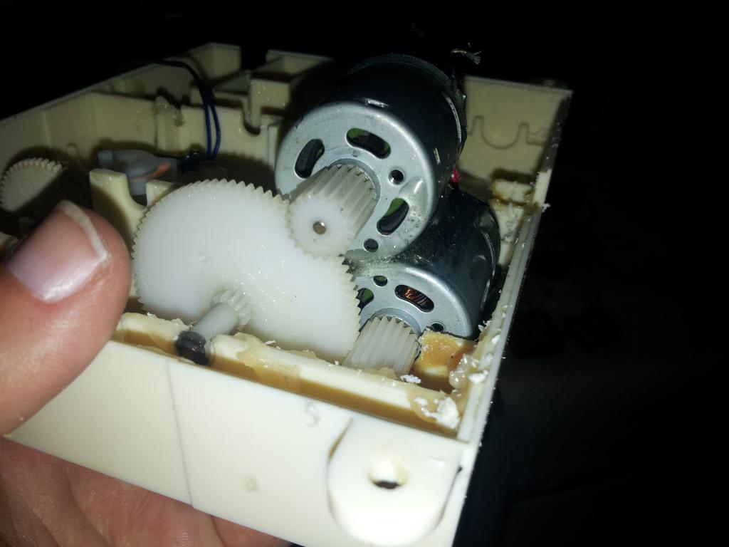
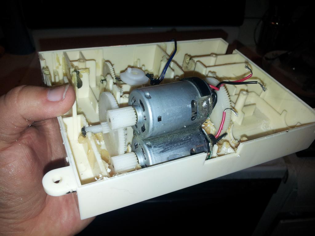
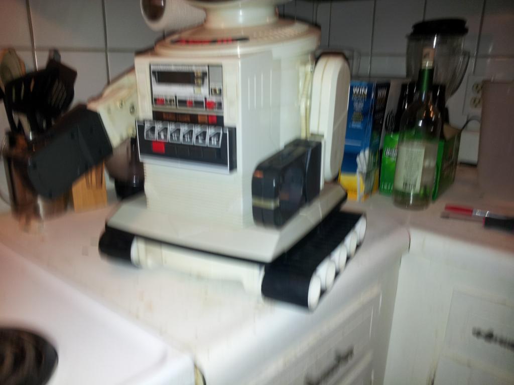
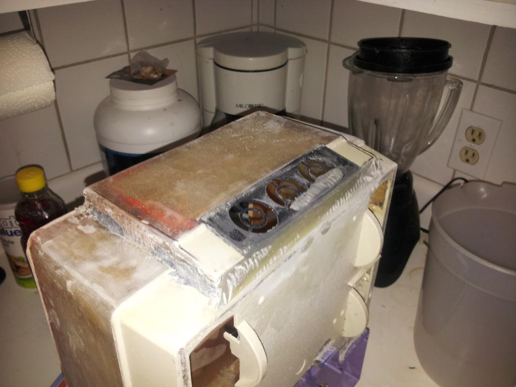
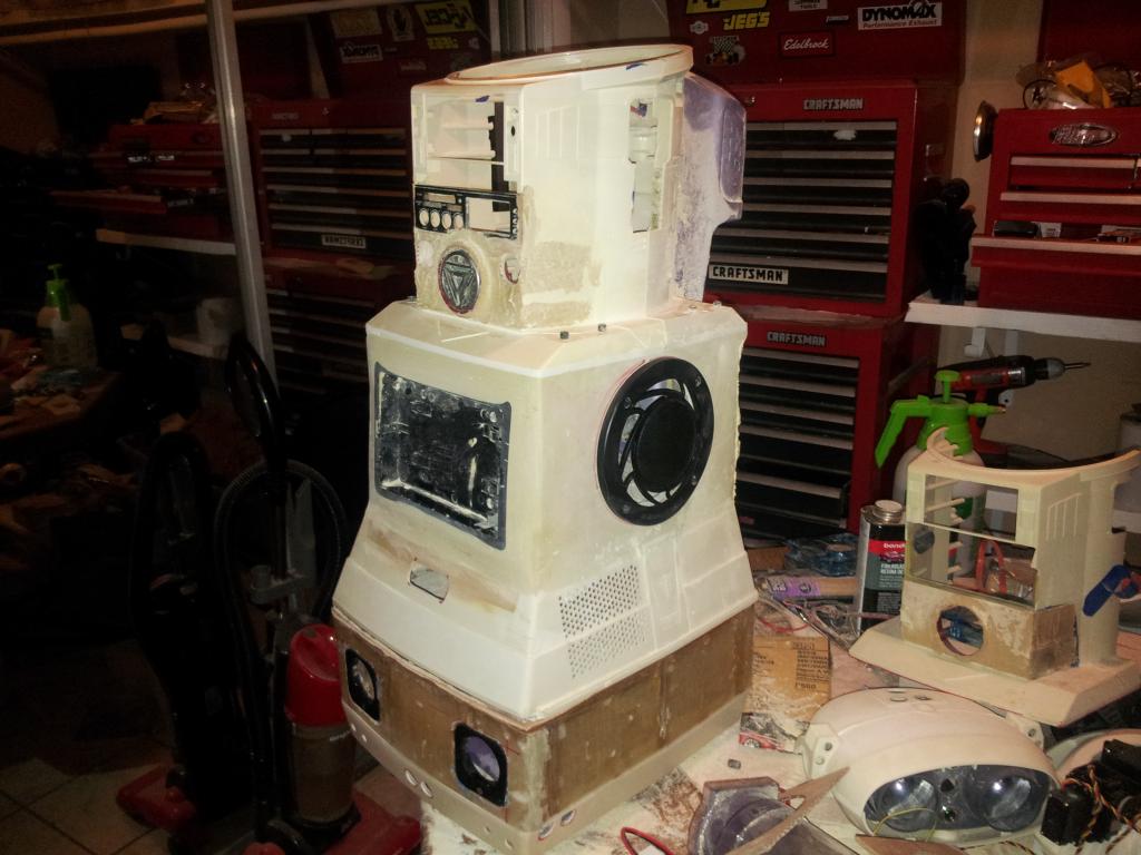
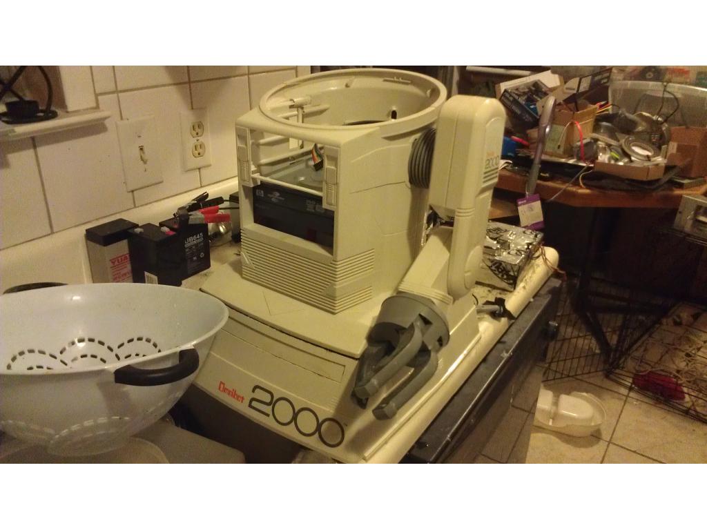
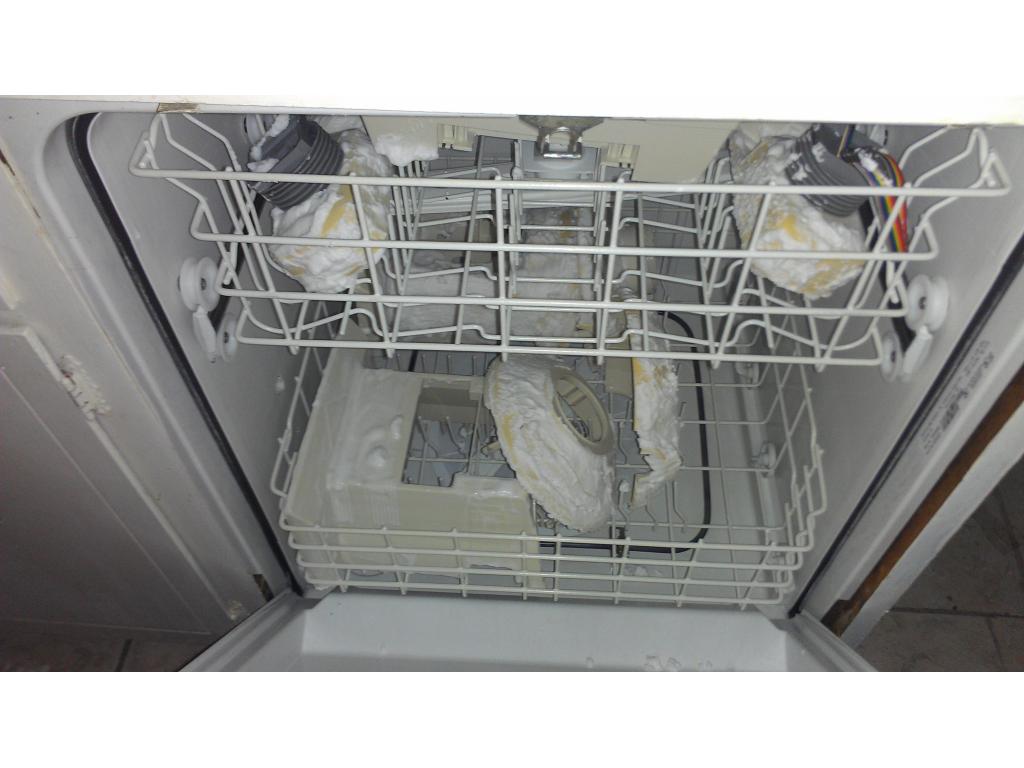
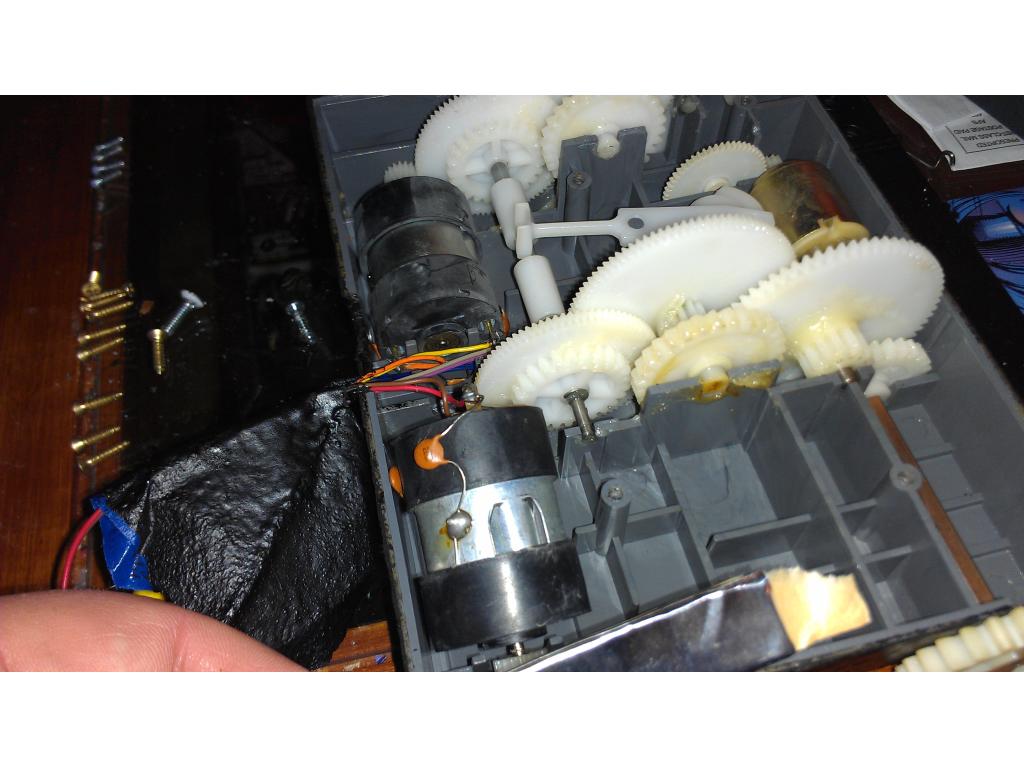
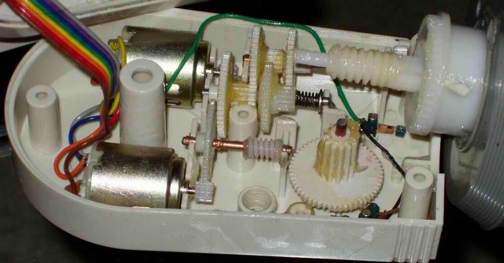
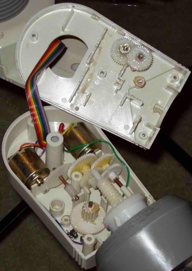
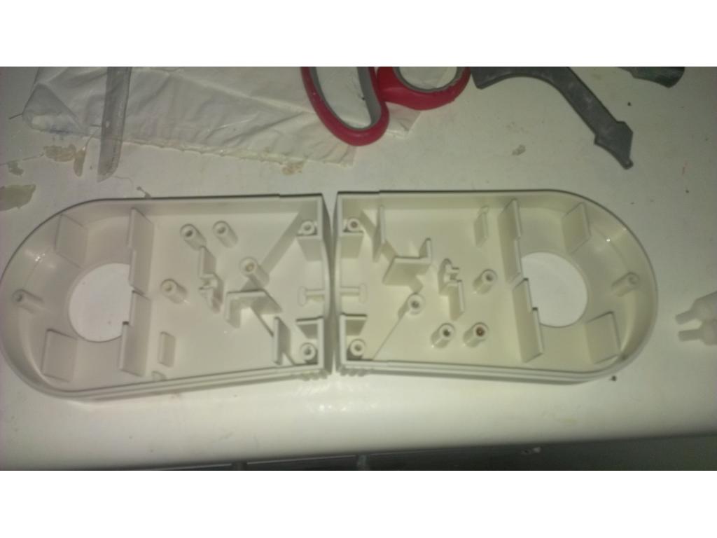
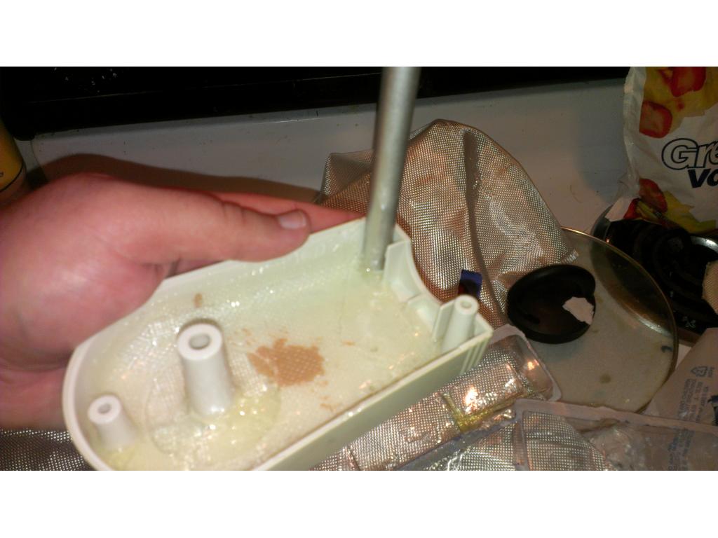
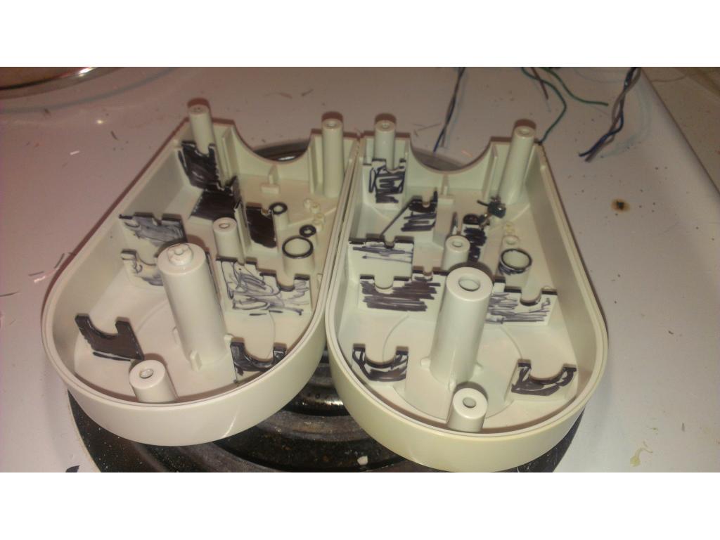
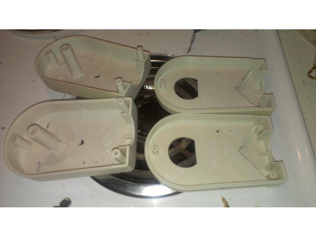
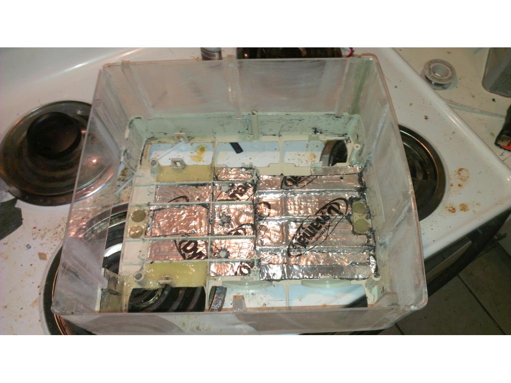
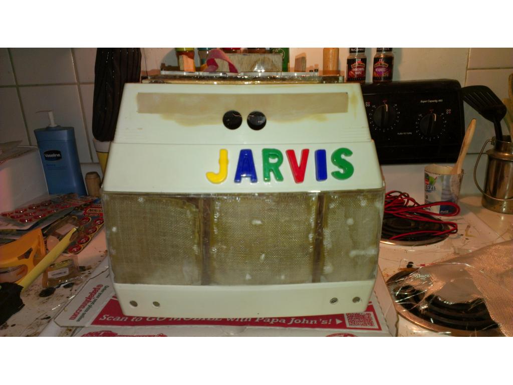
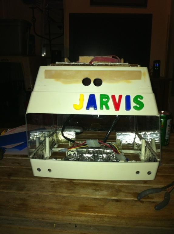
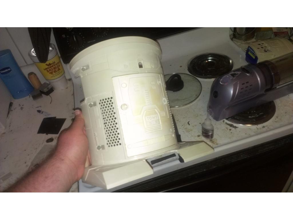
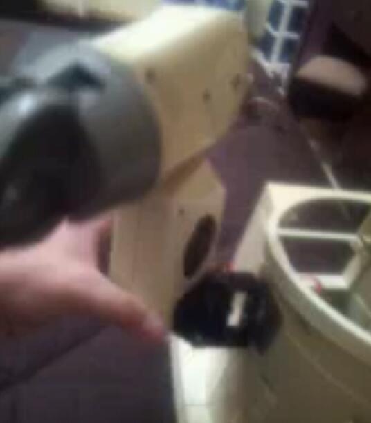
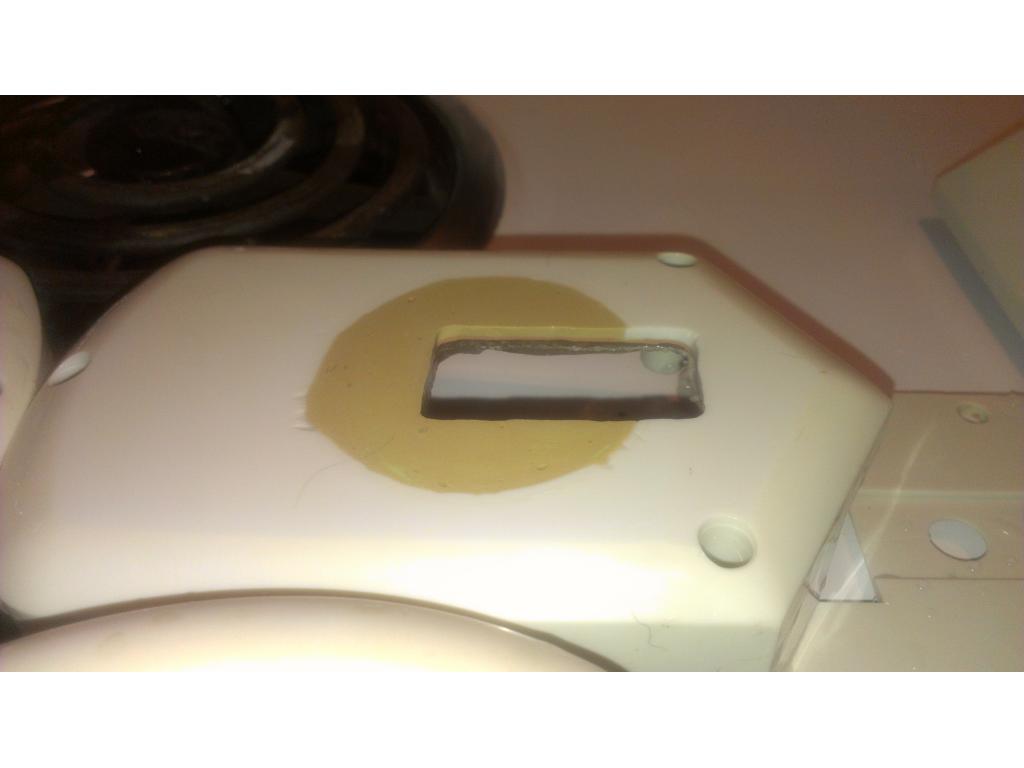
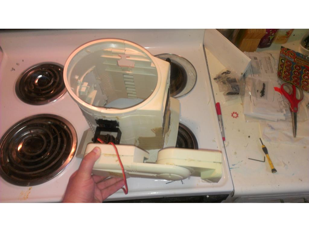
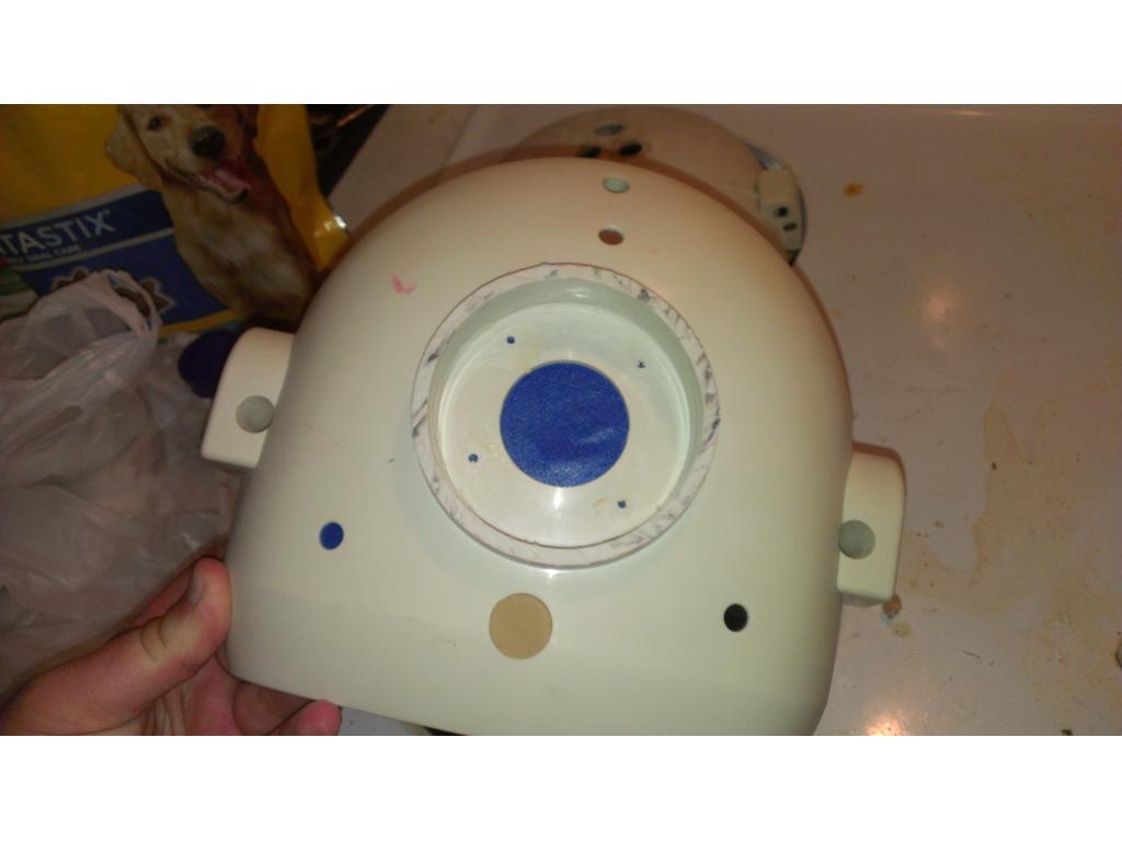
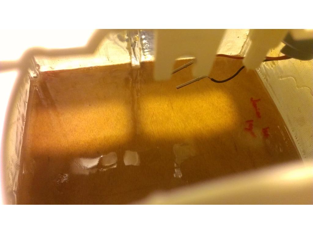
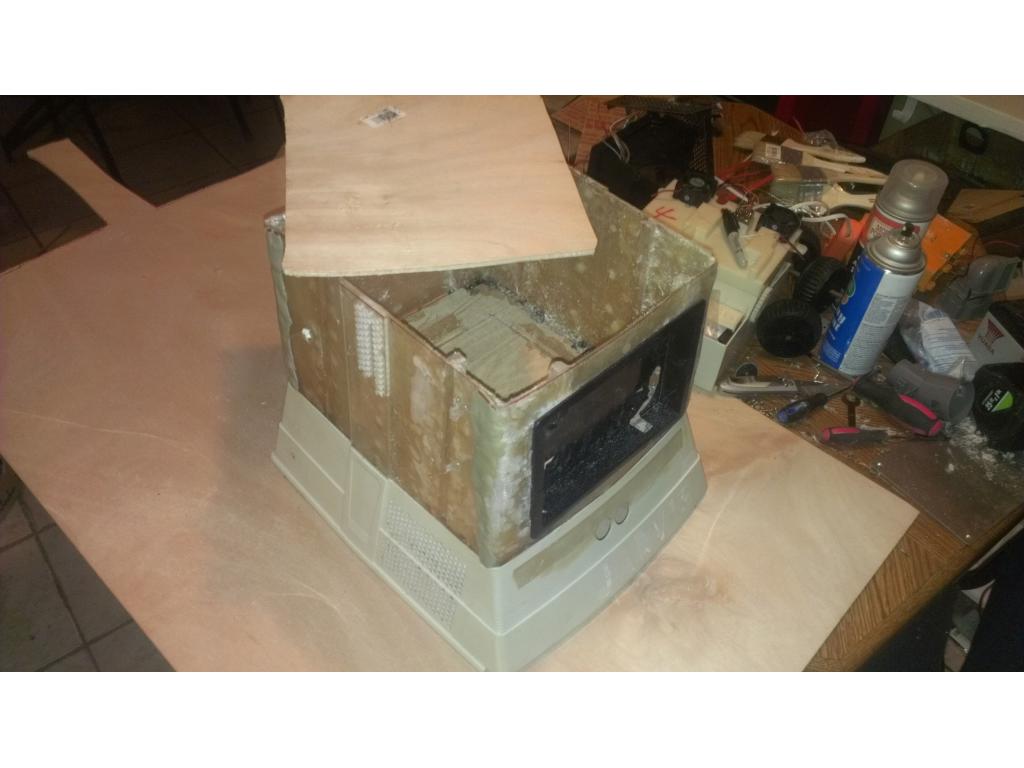
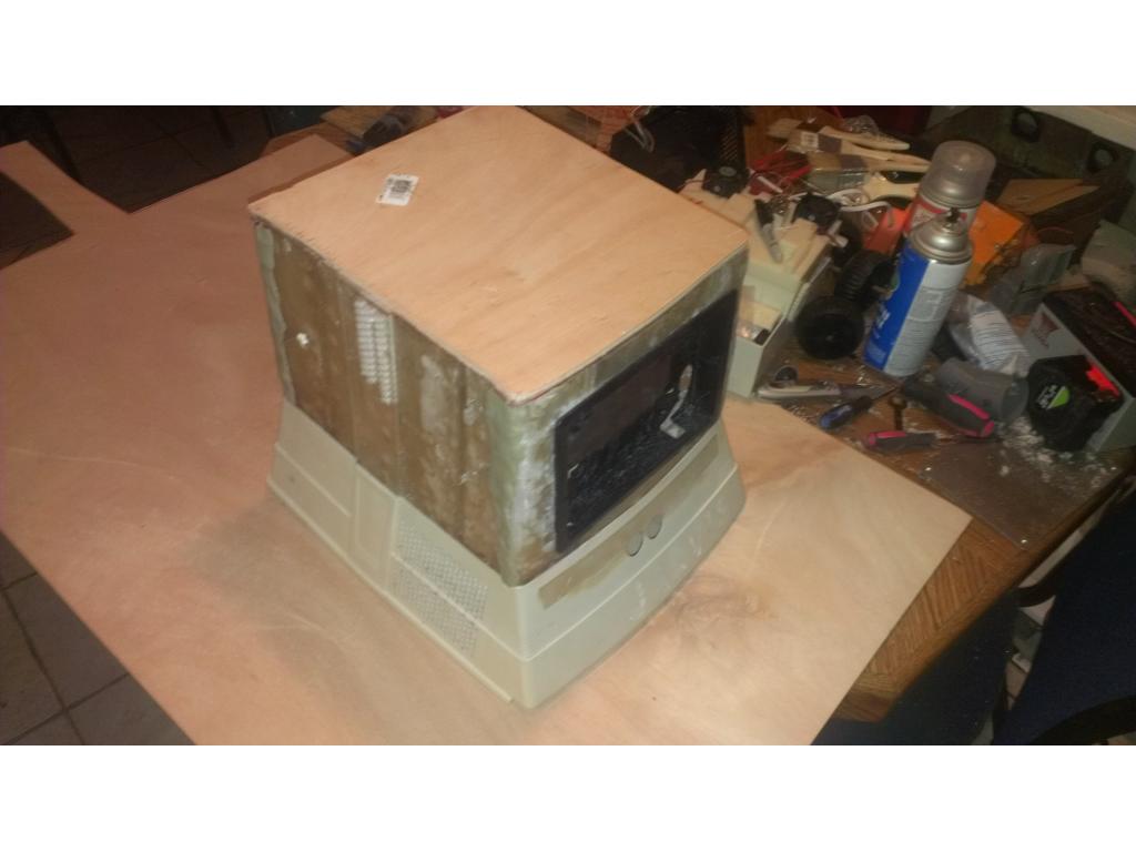
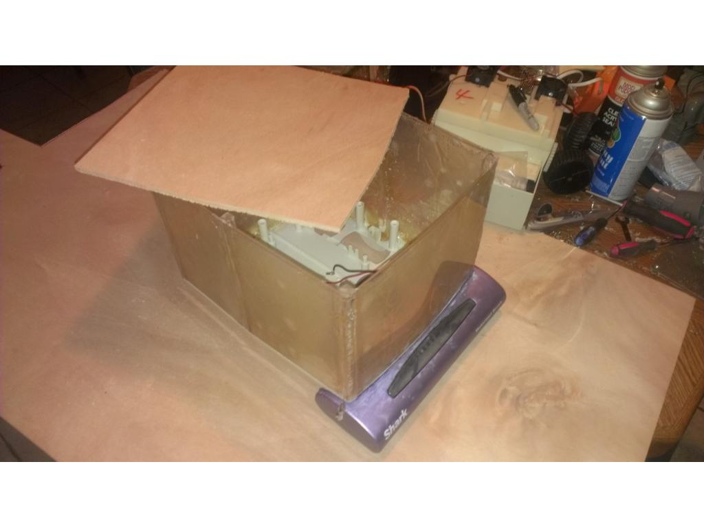
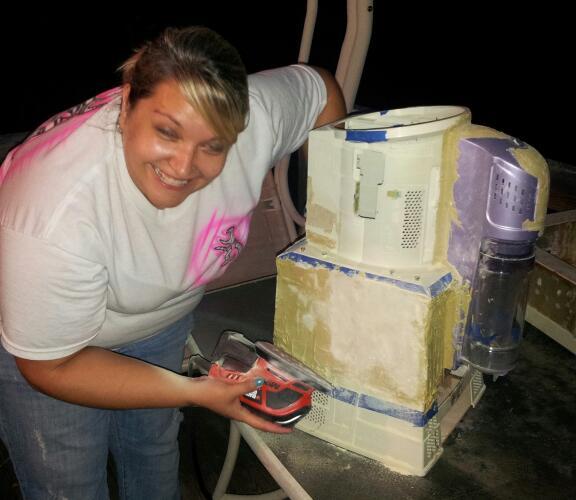
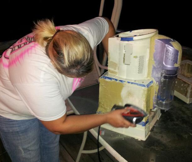
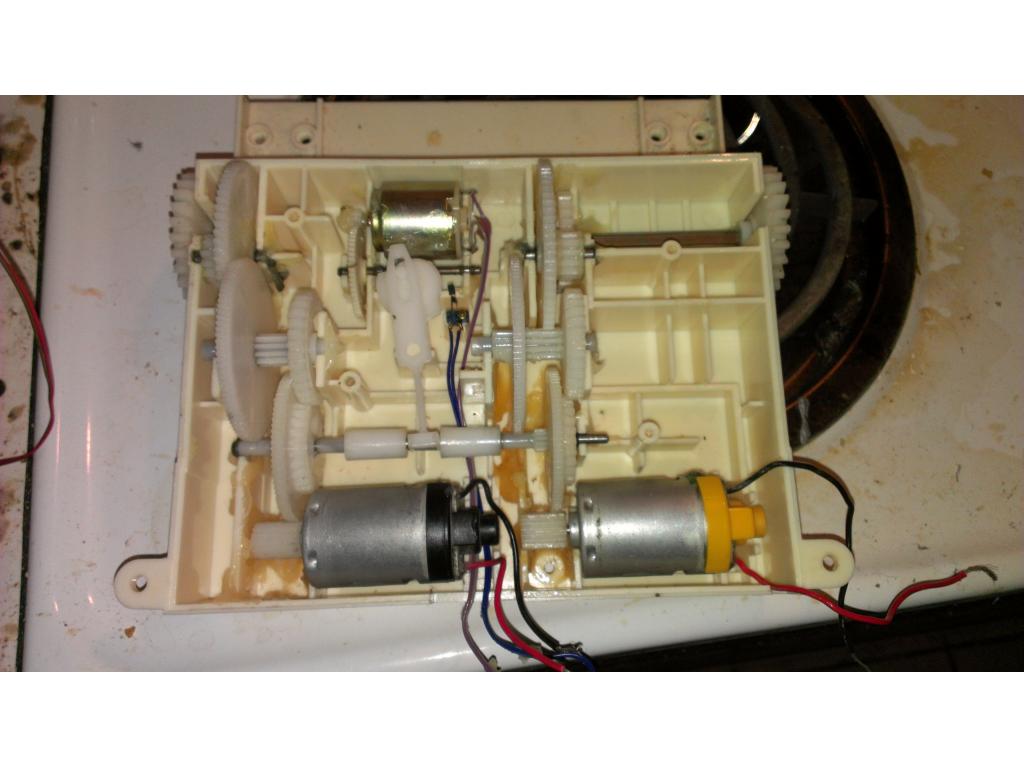
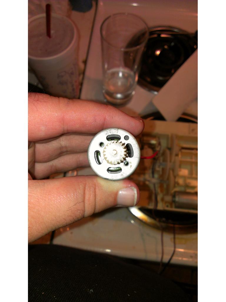
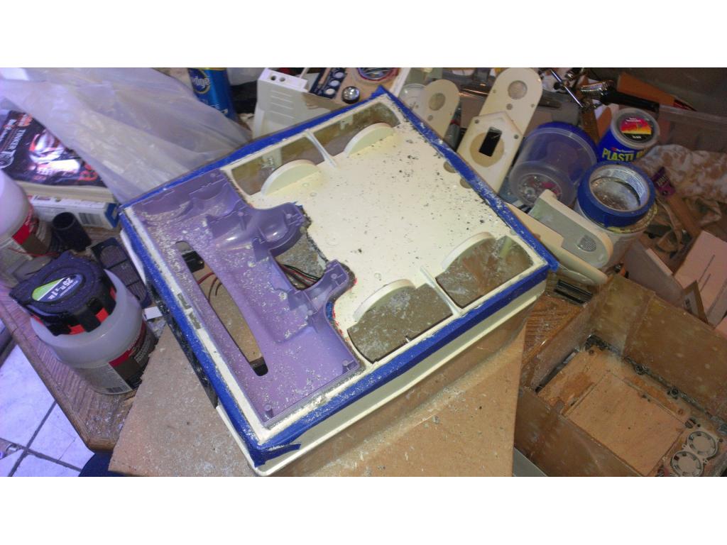
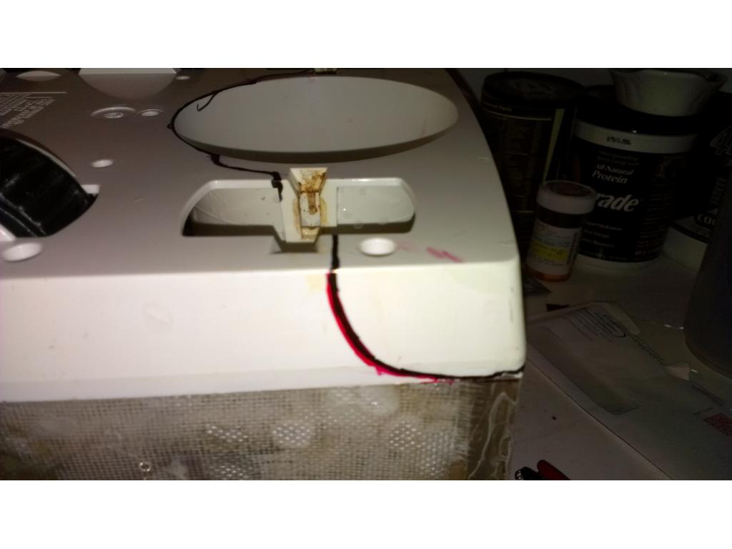
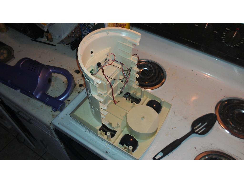
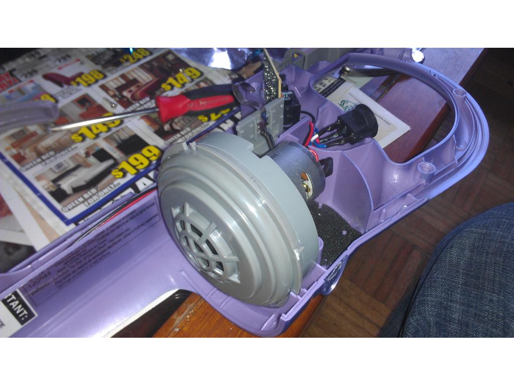
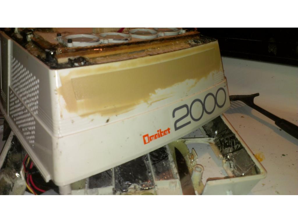
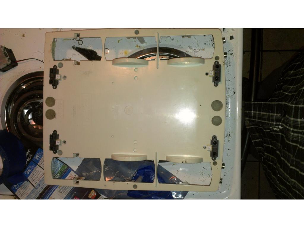
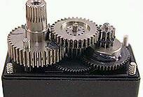
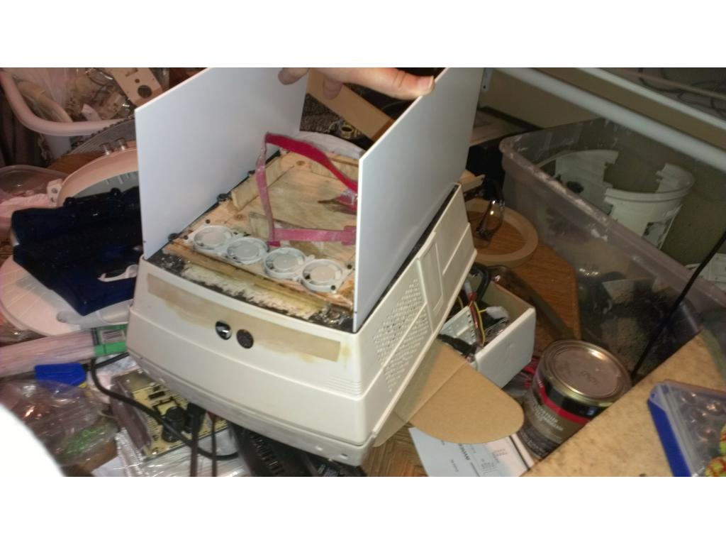
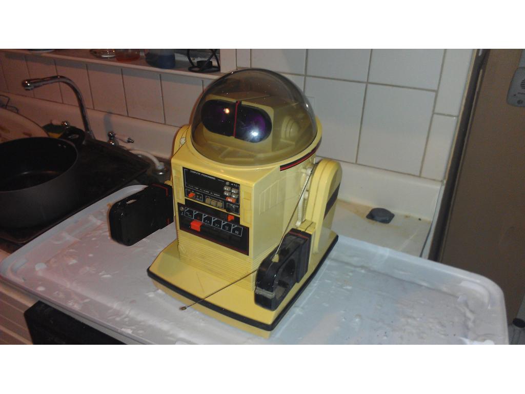
Ok my girlfriend went home so I have a couple nights to get the project working. I removed all factory electronics without cutting any wires. Brain and everything is intact so I'm putting all of it on eBay. Might get me 50 to 75 for a perfect set of guts. The bot has Brown discoloring in some places. I have it in the dishwasher with 3 to 4 cups of bleach and regs dishwashing powder. If this doesn't do the trick any other ideas? I don't know strong the OEM drain is. There's 8 sets of plastic gears so I see why its loud.
Check out Vanilla Ice in the Project Showcase section of the Forum. There's a lengthy discussion of using Retr0Bright.
http://retr0bright.wikispaces.com/
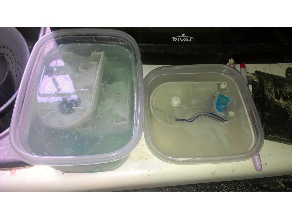
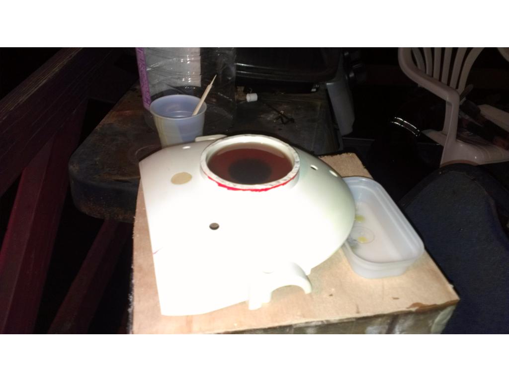
Ok I went to sallys beauty supply and got a large bottle of peroxide layup. That's peroxide that is already gelled. It was 3.50 USD. Then a tub of oxy clean powder for about 3.50 as well. Last night I washed parts in diswasher with 3 cups bleach and barely made a difference. So now I'm trying the retro bright peroxide method!
That all seemed like too much work to me so I just painted mine like DJ did his omnibot - I just changed the color scheme on mine. You can use plastic spray paint and it works really well.
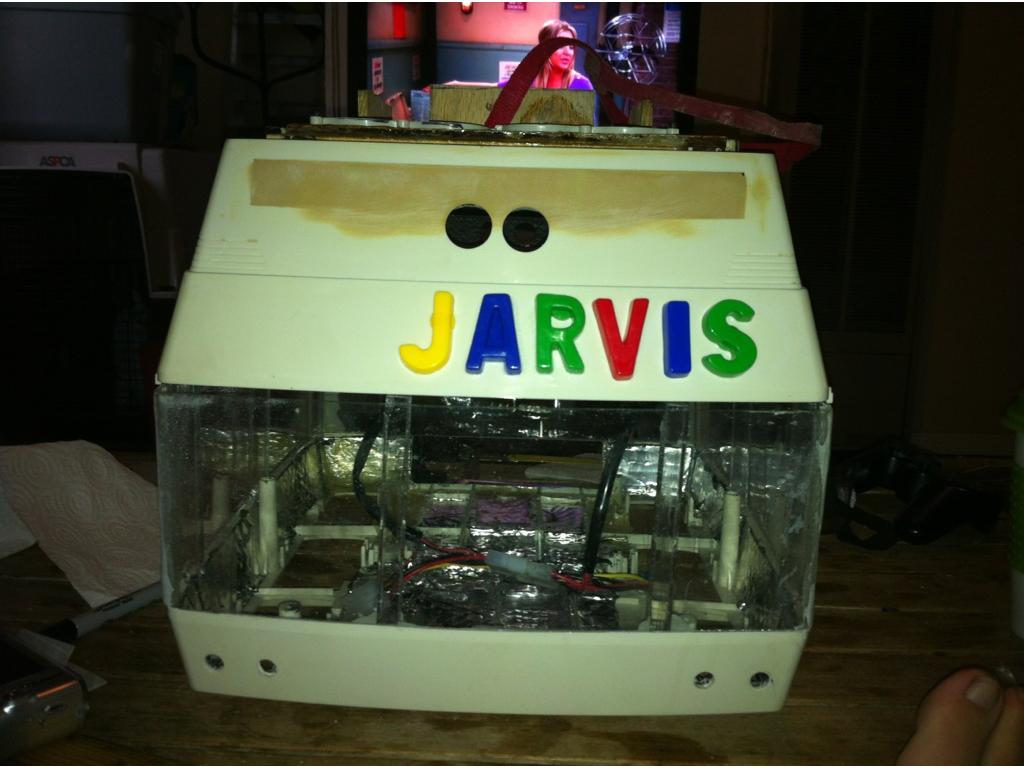
I have a weird thing about stuff being nice as possible before nodding. I actually plan on a automotive quality paint job from a body shop however I won't do that until all cutting , molding , fiberglass ext is done. So ill give it the college try but in the end its getting paint. but that could be 3 months from now so I like it to look good as possible in progress pictures.
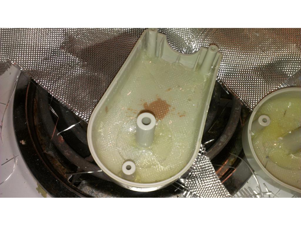
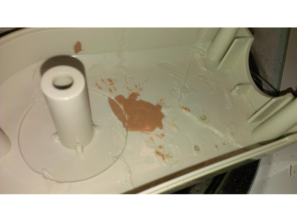
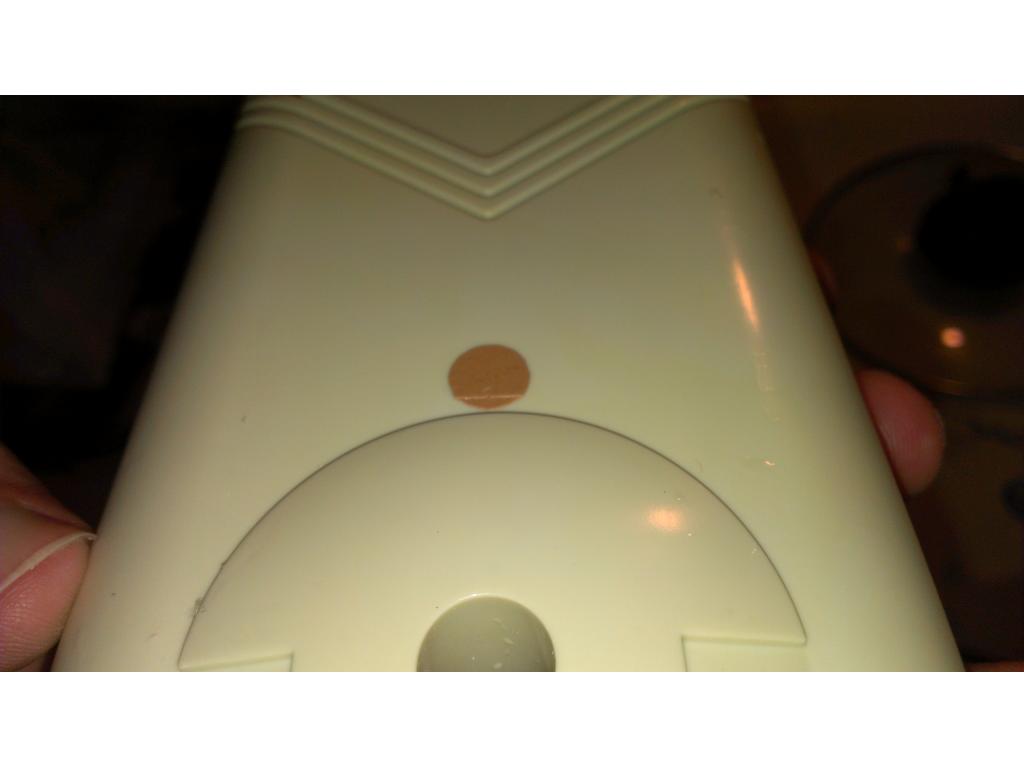
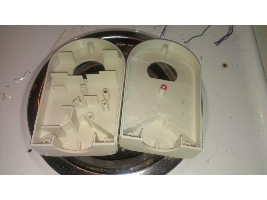
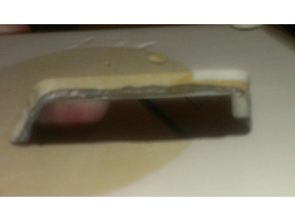
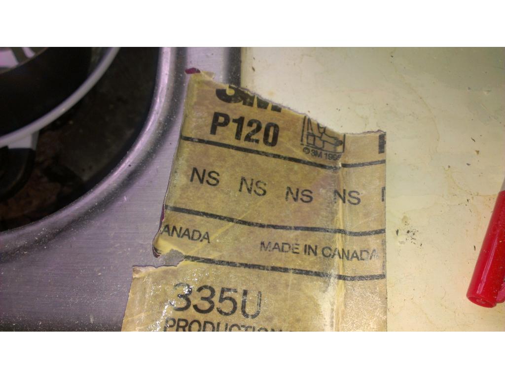
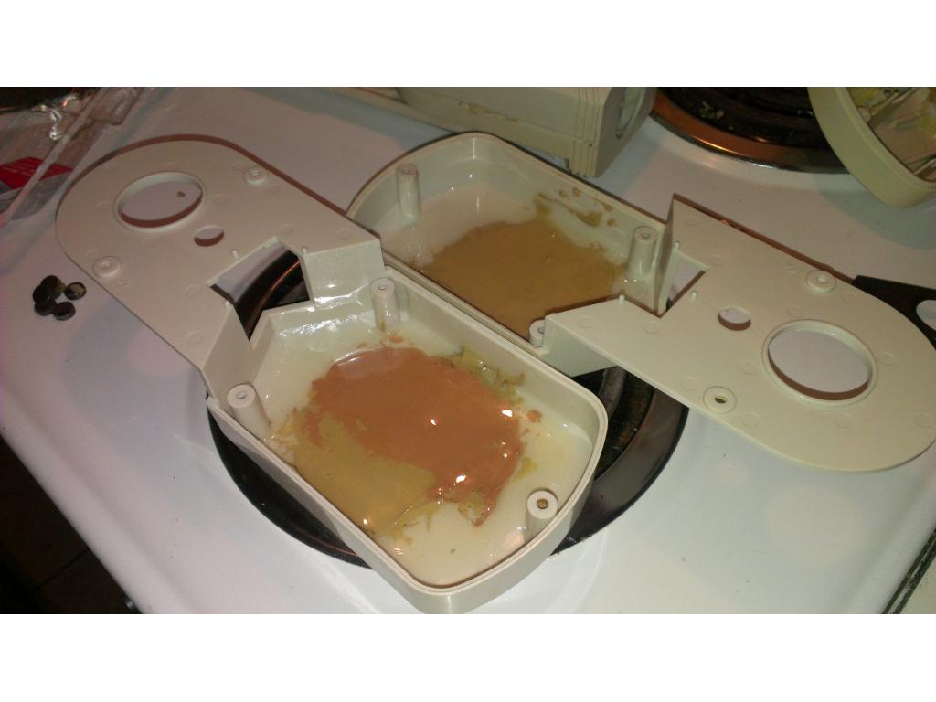
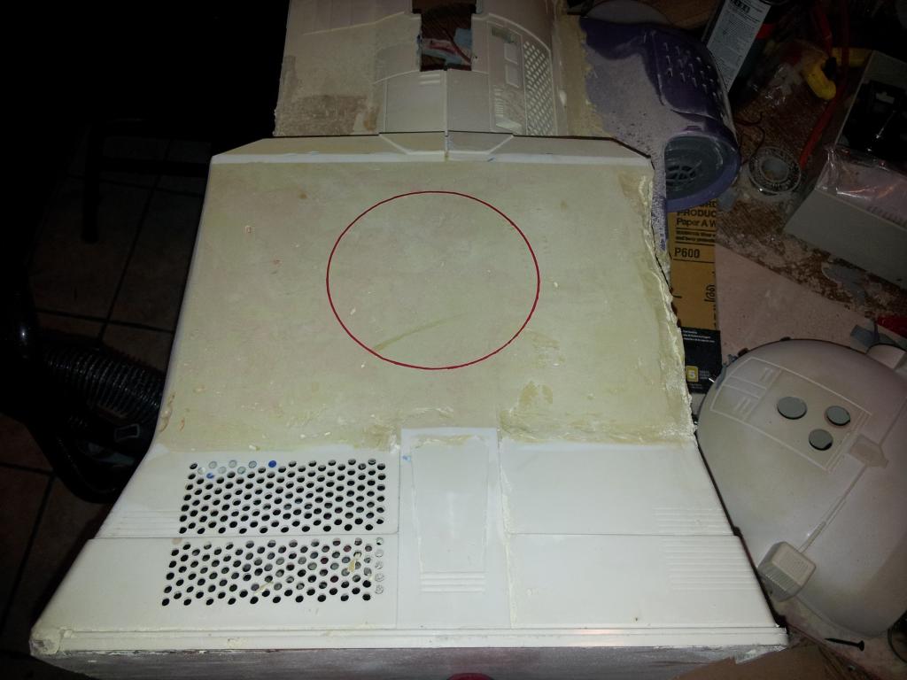
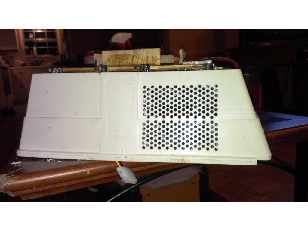
Ok update after 2 days of cleaning. I went through a bucket of oxy clean and a pint of 15 percent hydrogen peroxide and it definatly lightened the Brown iv damage. However they were only about half gone after many hours of treatment in the sun. So I took remaining oxy clean and added a couple scoops every cycle and ran it through my dish washer about 6 or 7 Times. This proved more effective than whitenening with retro bright type formula. Then before this last load I took 400 grit sand paper and soap n water to really stubborn areas which worked well from just a few minutes but your fingers will hurt tryin to get into those really sharp crevesas and curves. The front chest piece is completely clean , as well as bottom and lower half of omnibot. Now its just the edges if the arms and top of the head I need to clear up.
Cool! Pics?
I'll post pics this evening hopfully after I've finished cleaning up the edges of arms and top of the head. In cleaning I've noticed small damages the bot has incited that has made cracks and splits in a few places. I will definitely fibreglass around these mounting points and cracked areas i previously couldn't see through the browned tar.
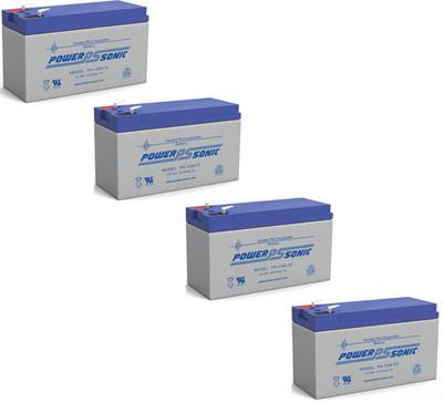
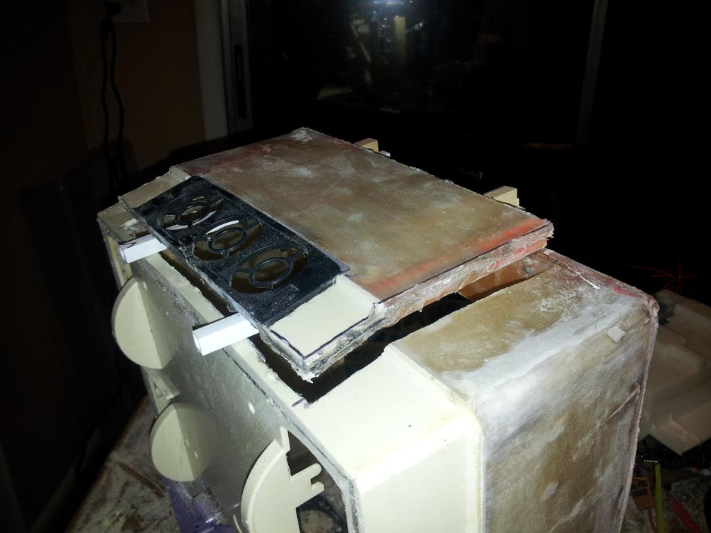
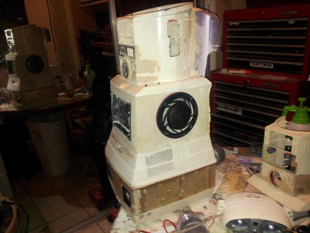
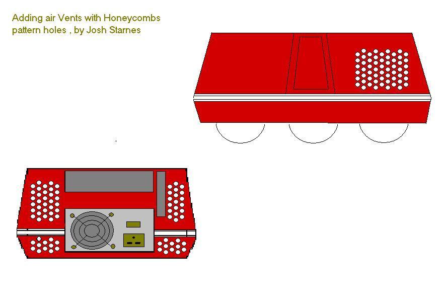
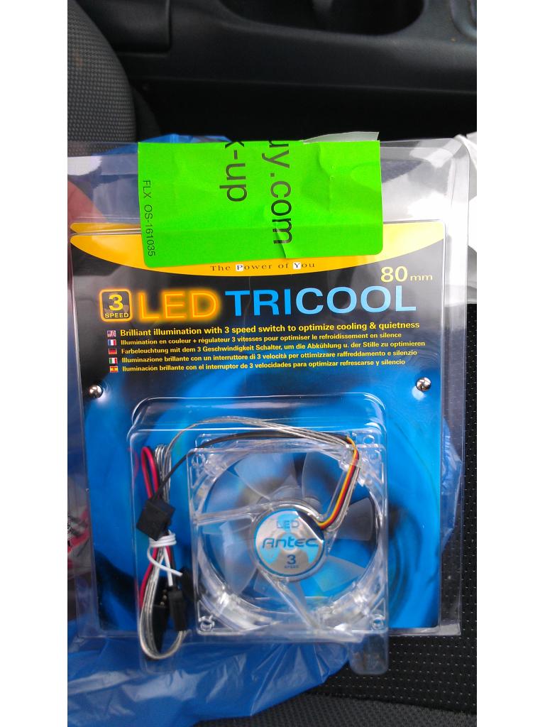
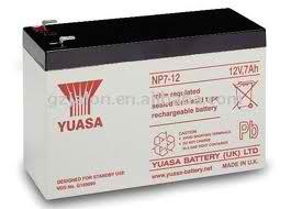
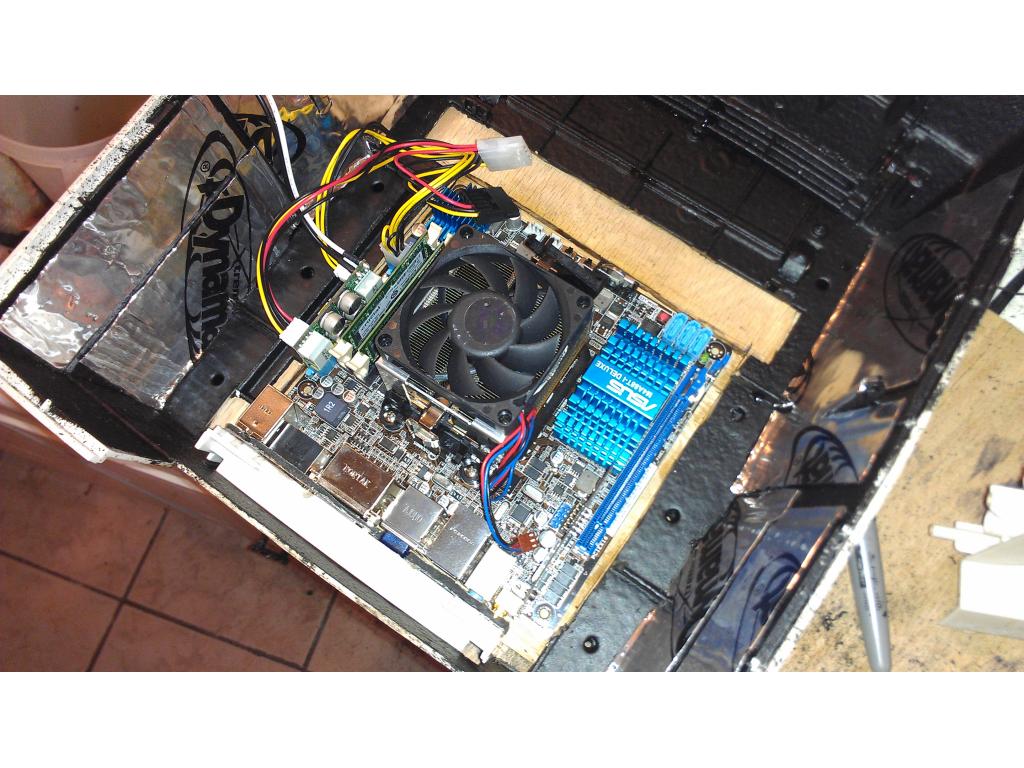
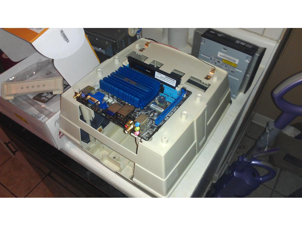
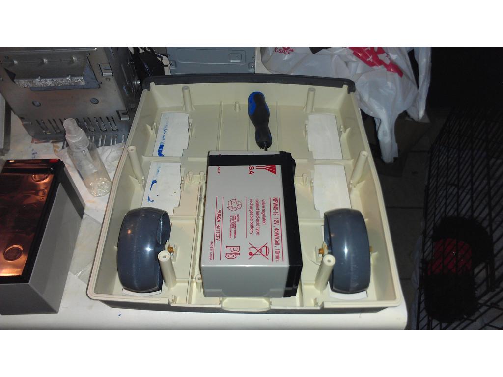
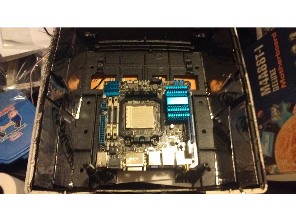
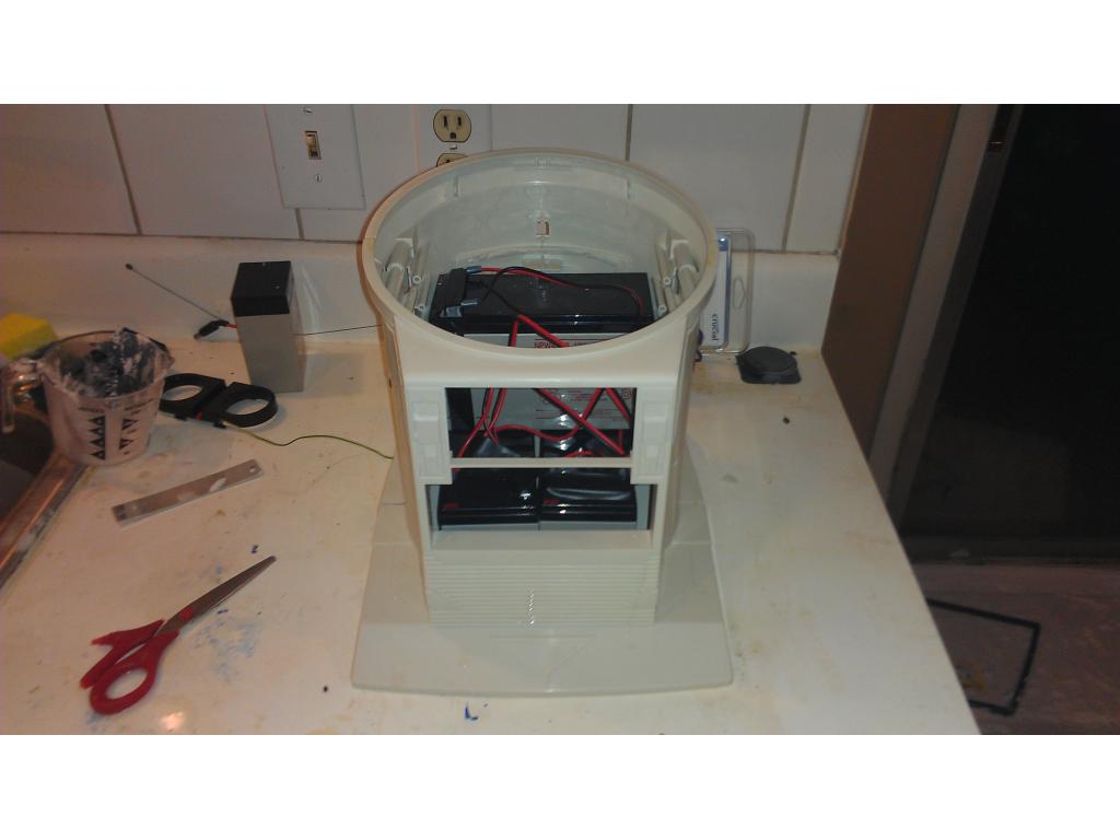
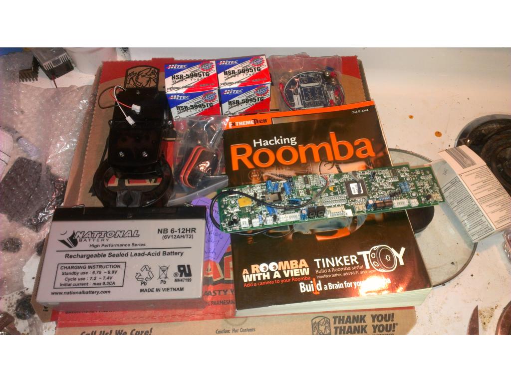
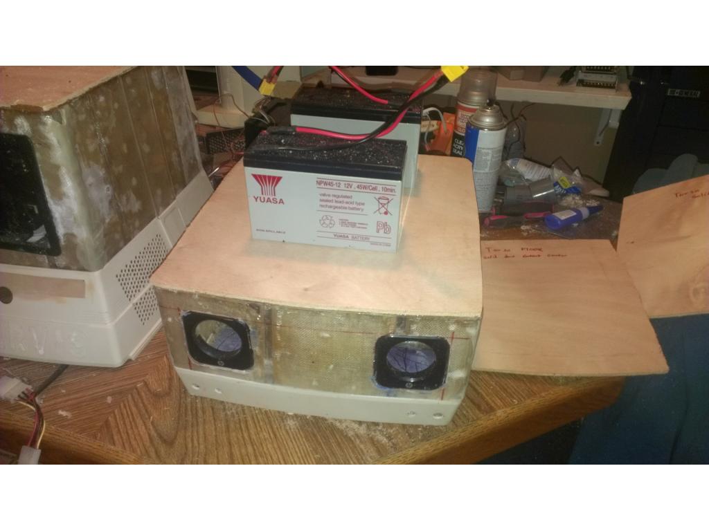
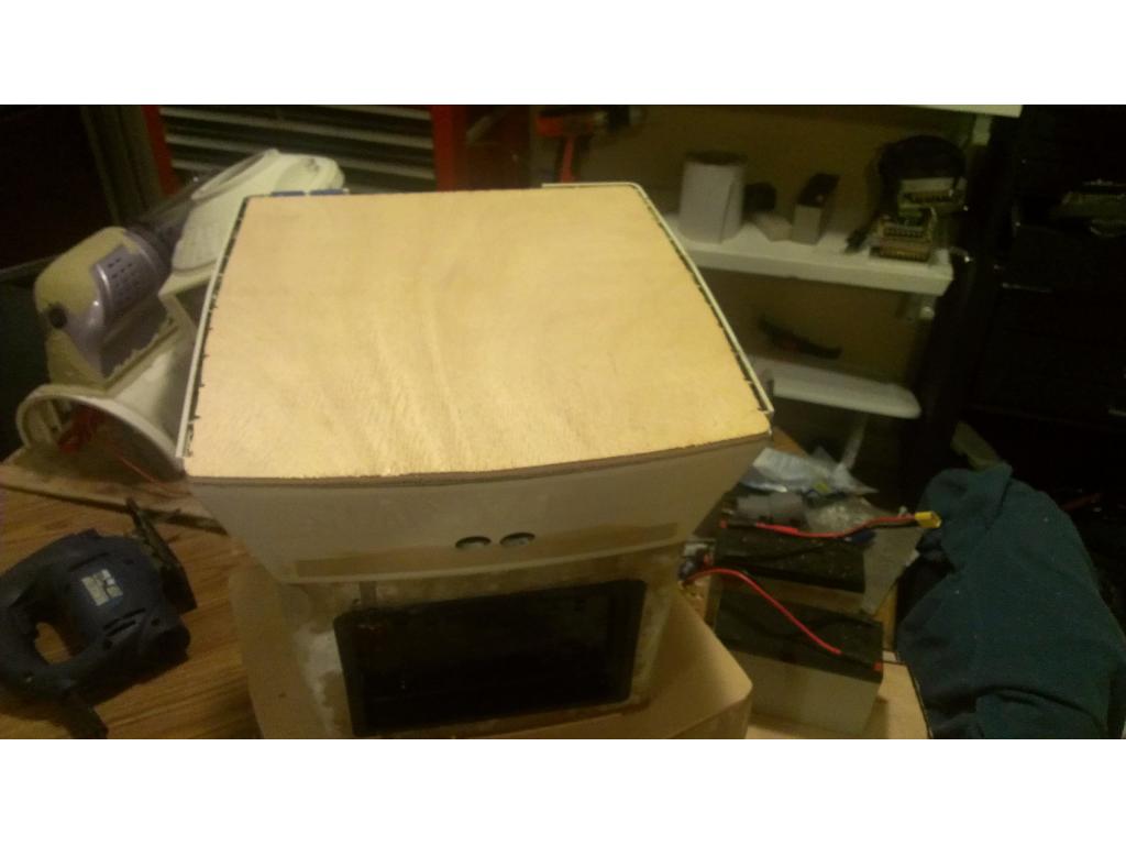
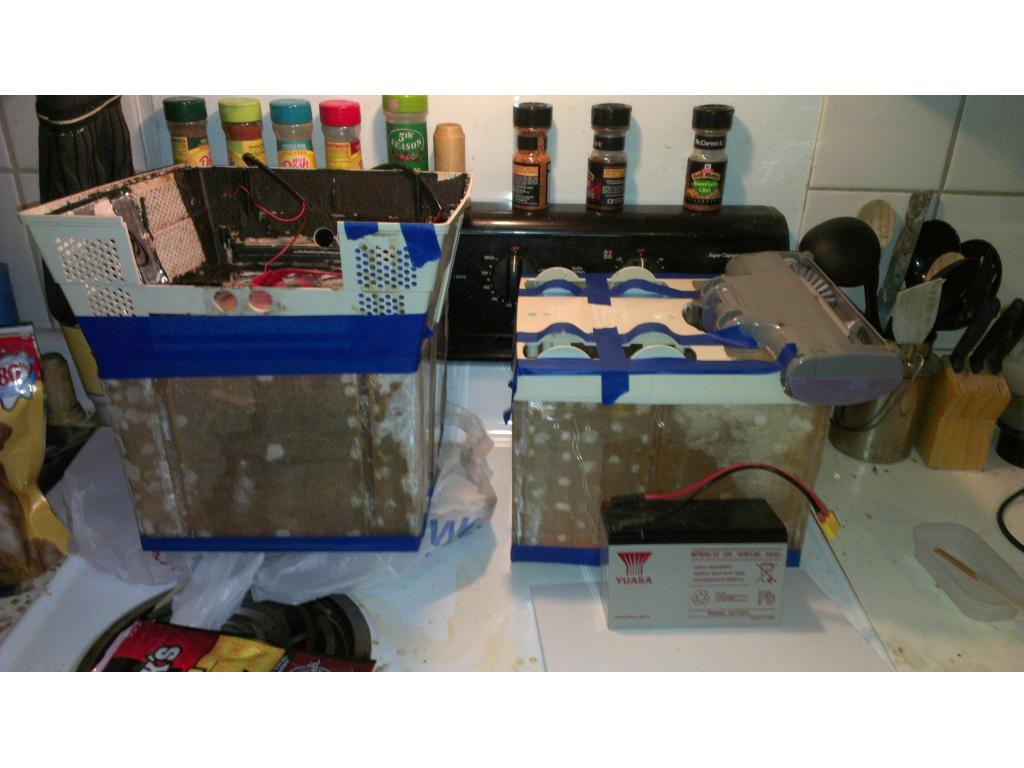
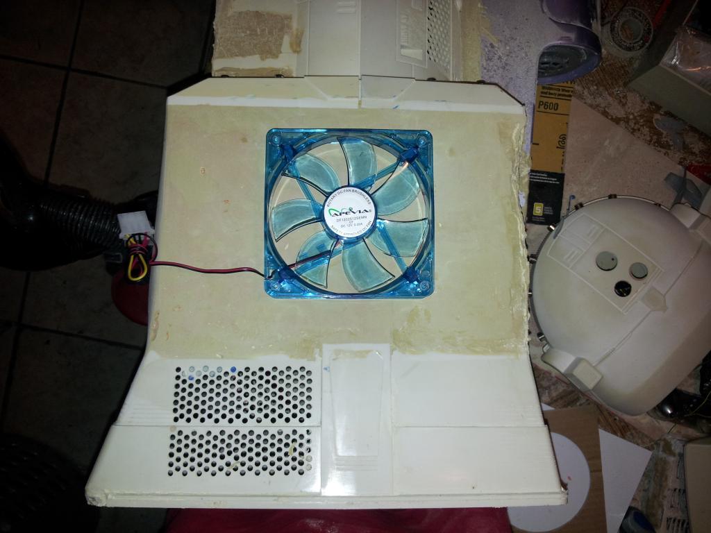
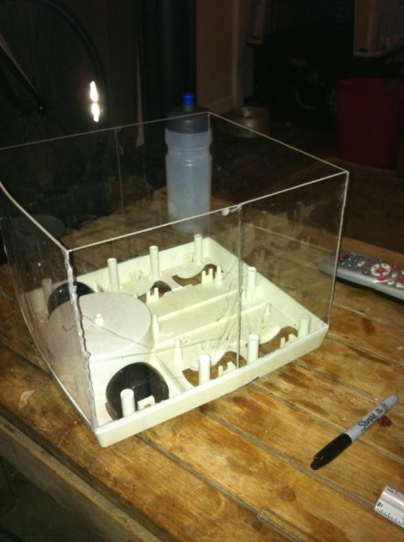
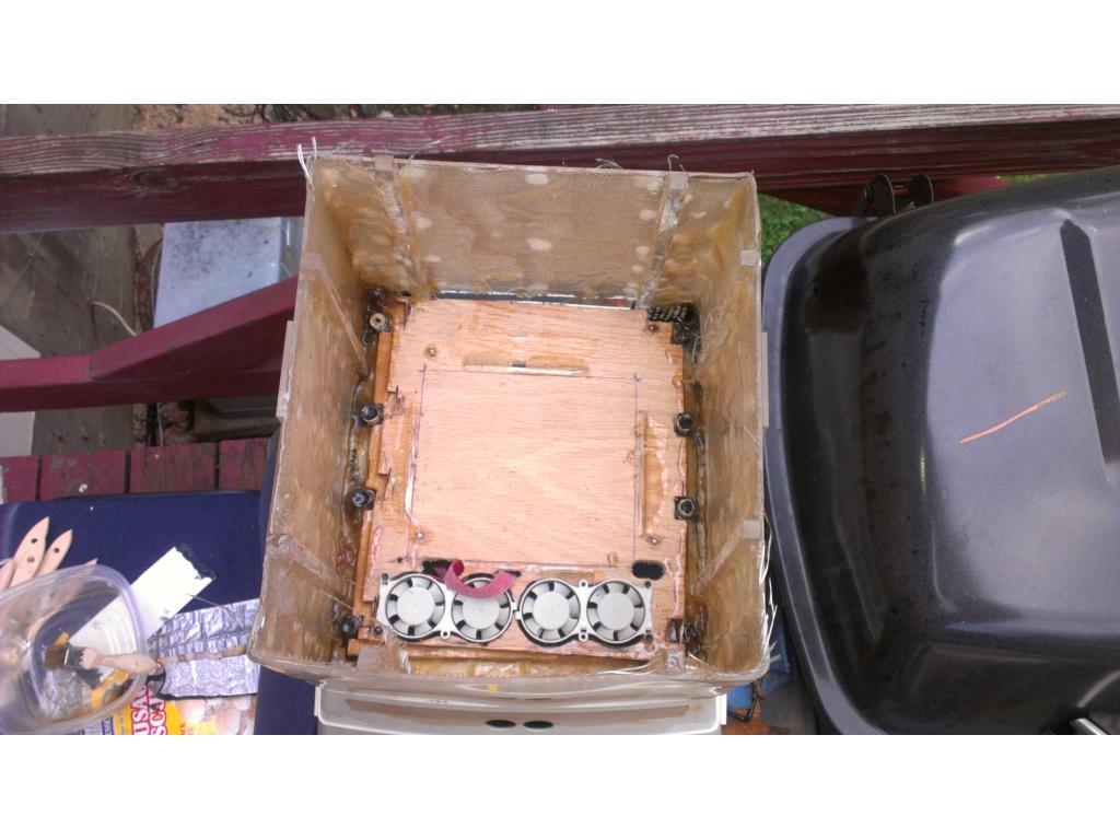
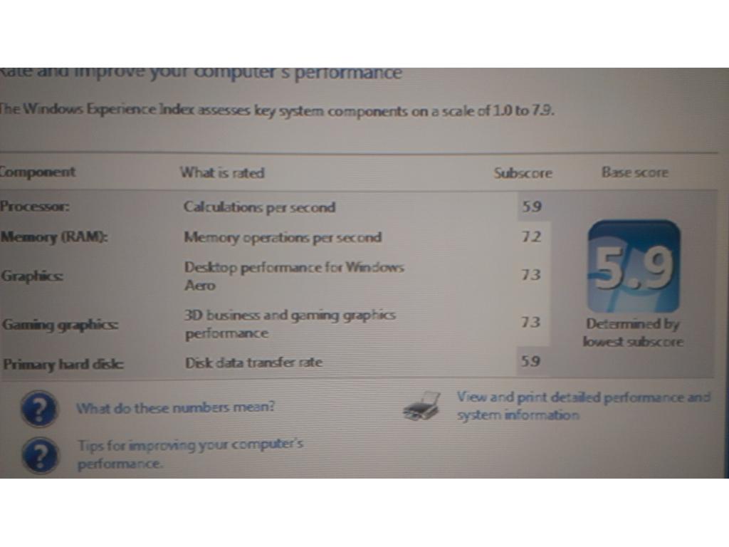
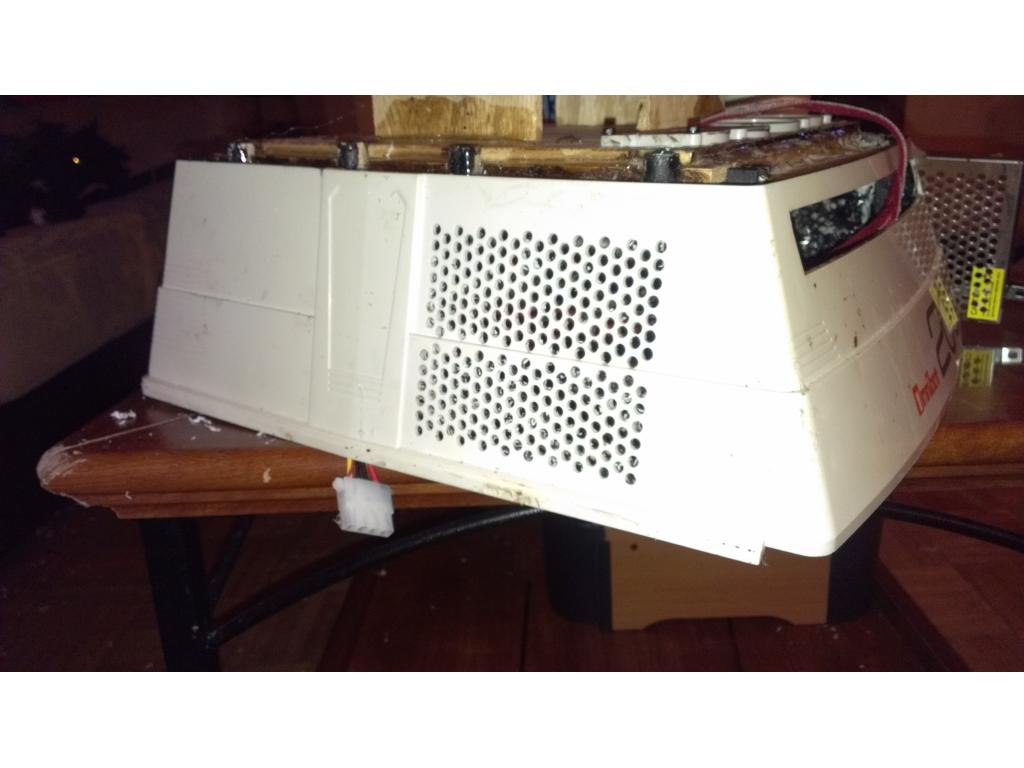
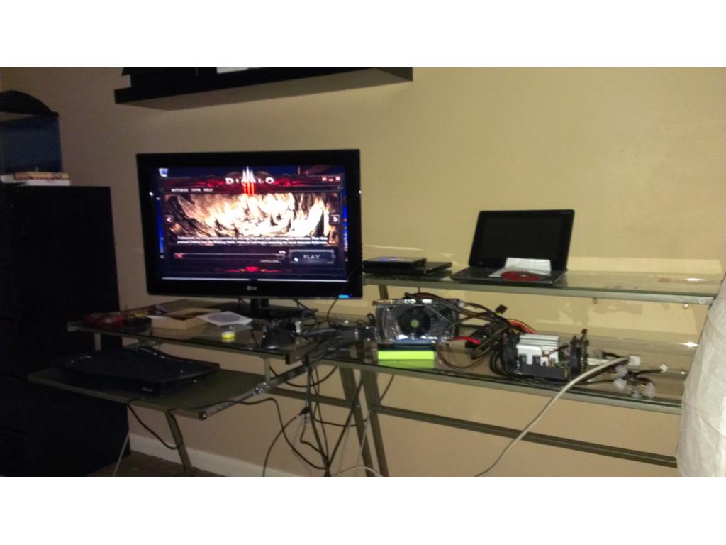
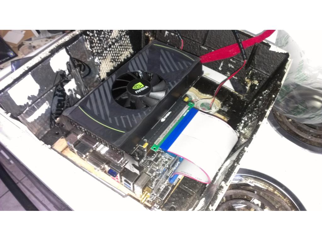
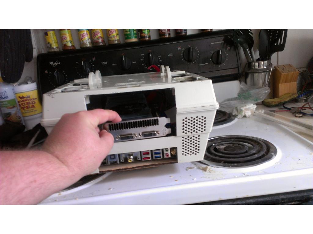
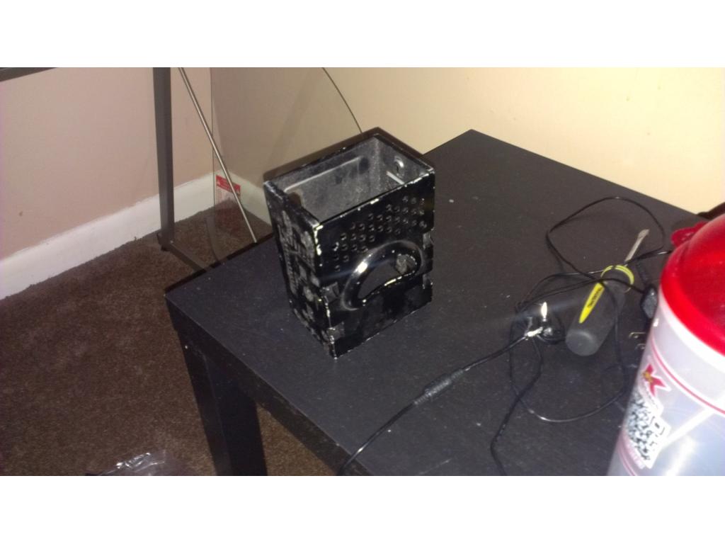
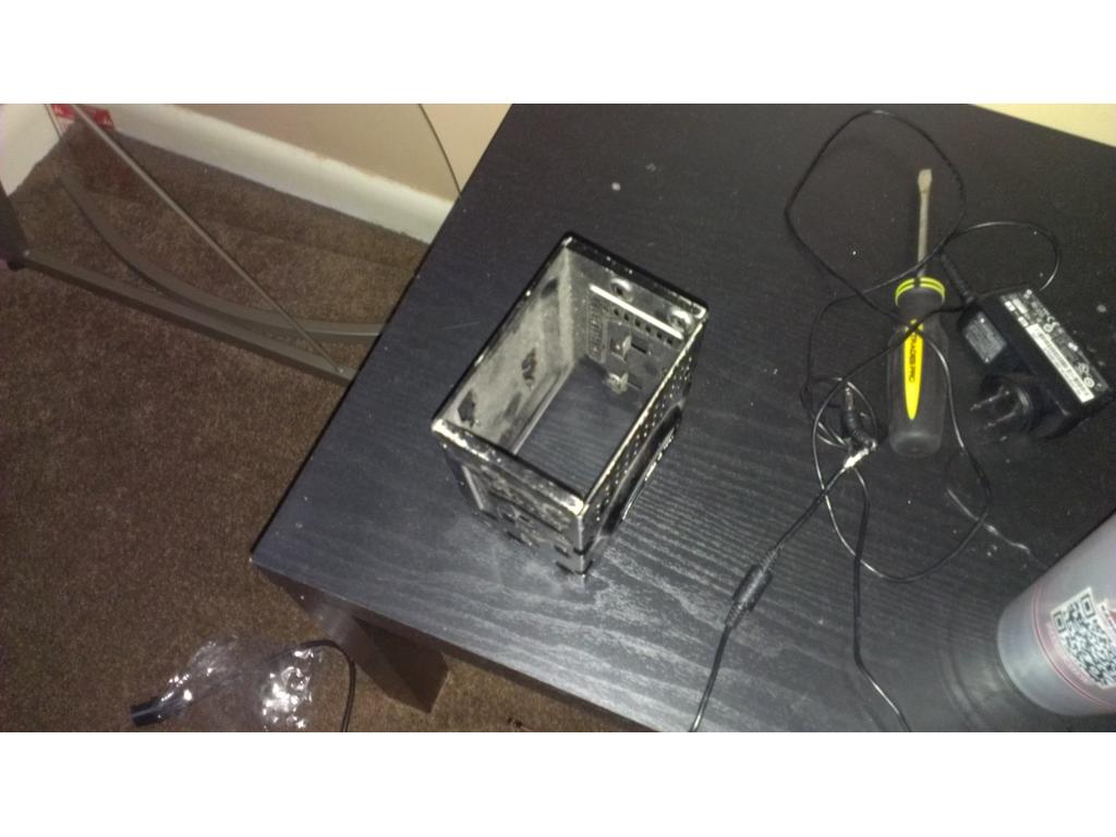
I gotta fit lots of stuff in this bot. I think need 20ah worth of batteries , I'm thinking of doing three 12v power sonic sealed batteries. The motherboard draws 90w max but more like 40w average. It's just a dual core atom 330 with nvidia ion gpu. This motherboard came with a its remote for powering on and off , playing music and DVDs ext. I have a New HP lightscribe DVD RW data for the project and standard size 3.5 in Western digital 250gig Hdd , (the PSU is build in onboard) , I also must install a dc to dc regs power supply. This protects the electronics from spikes or drops in voltage. I have the Asus it eye I need to mount somwhere for the remote. This mobo has WiFi and Bluetooth built-in so connection to keyboard and mouse wirelessly is easy. The mono is 6.5 in square and 2.5 in thick. I def need to open up some vents . I'm thinking 5 inch fans mounted horizontally, one above ez b and another above mobo and a exhaust fan somwhere low. I need to install a switching power supply (battery charger) onboard so that all I need to do is plug up a strong act adapter and it charges at the same time pc is running. I removed the bottom counterweight and cassette player/LCD from the chest since that's not useful.
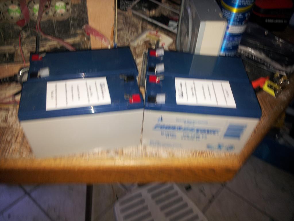
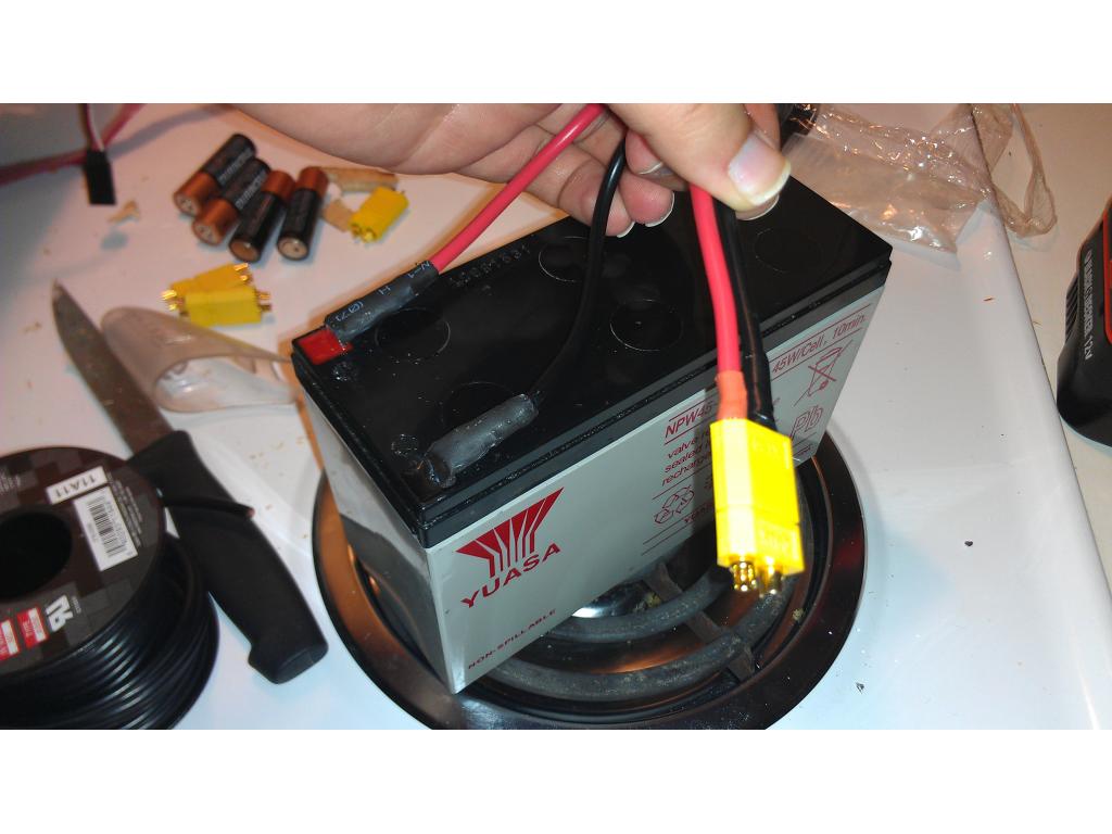
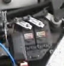
This is the batt I'm thinking off
So you are thinking of running 3 of those batteries? Cool. Is there room in the frive section for all three, to help keep the center of gravity low?
I believe I could remove the drawer and line three up side by side. That's like 15 pounds of batteries though. If I must ill just run two but I want.the bot to be able to go autonomous for 2 to 4 hours at a time without completely draining the batteries as it needs time to dock and recharge. Ofcorse I'm loosing the metal wieght under the drawer that wieghs about 5 pounds and took the cassette and LCD out so I'm not adding but about 7 to 10th pounds I believe in difference from batteries. Hopefully it will have enough weight the dog won't knock it over.
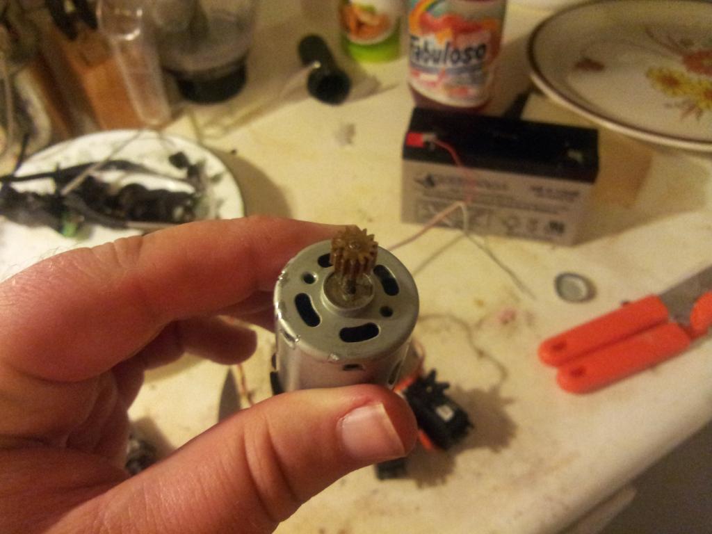
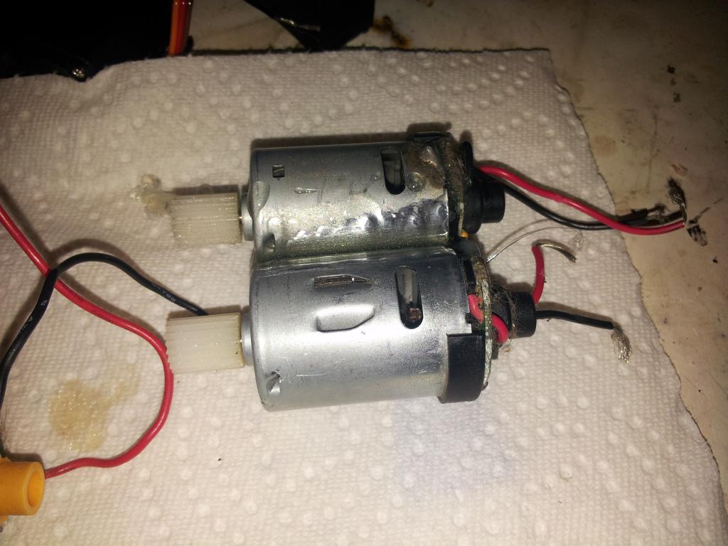
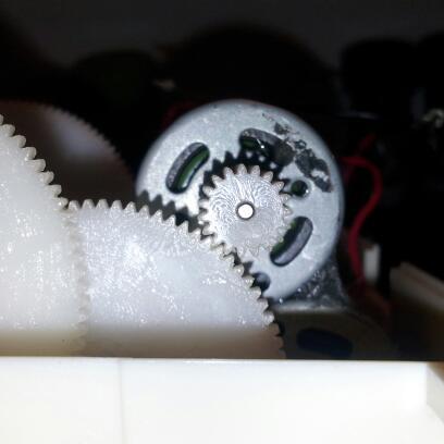
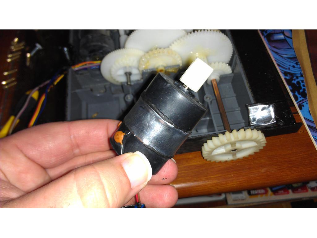
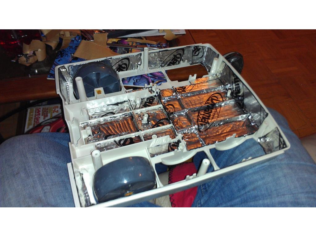
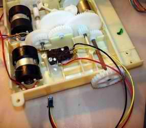
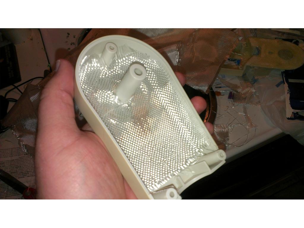
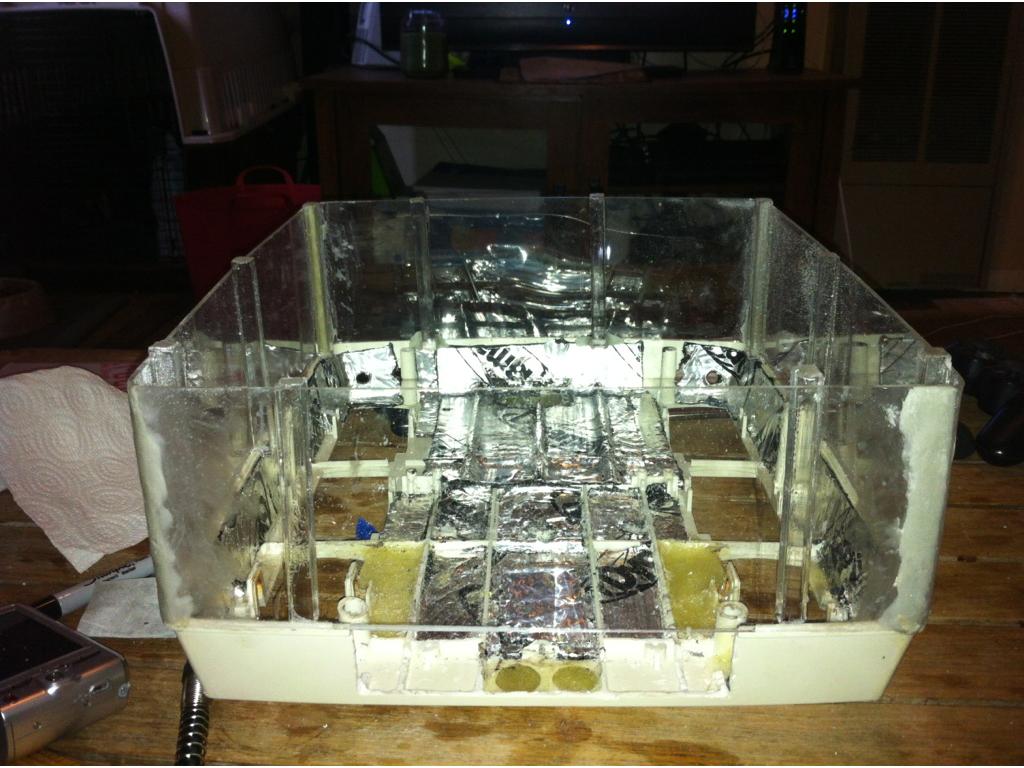
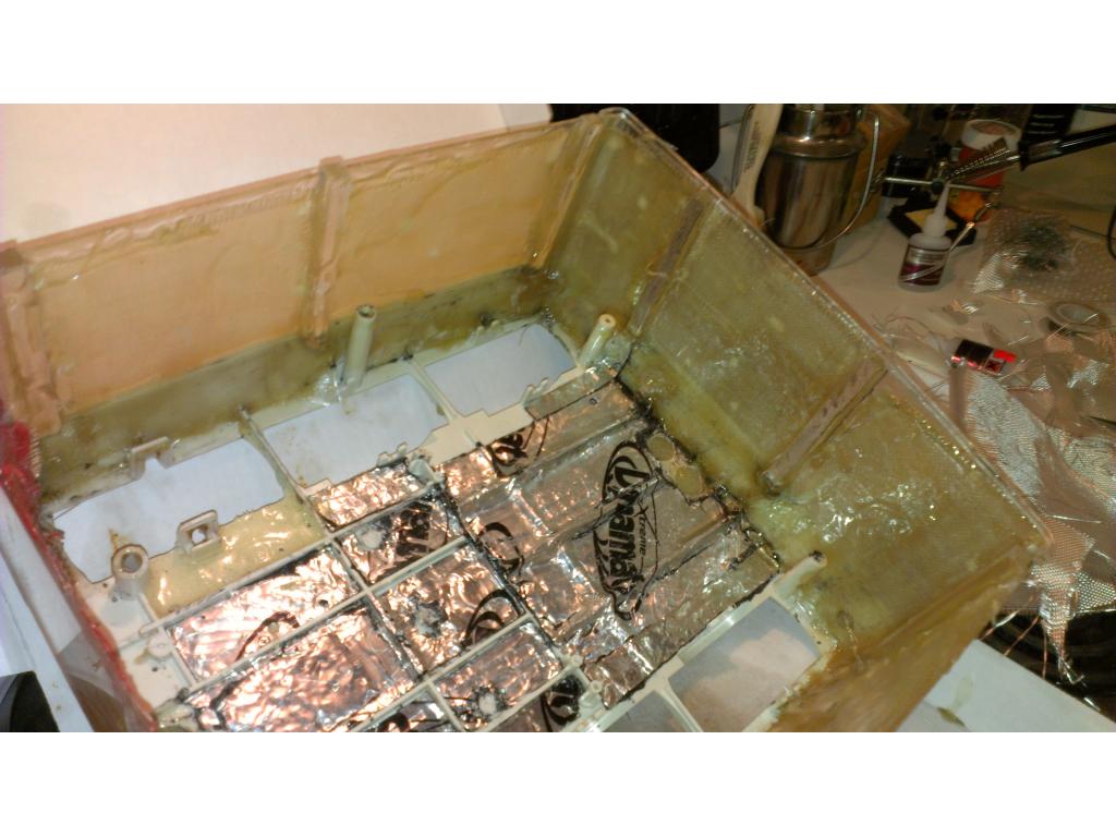
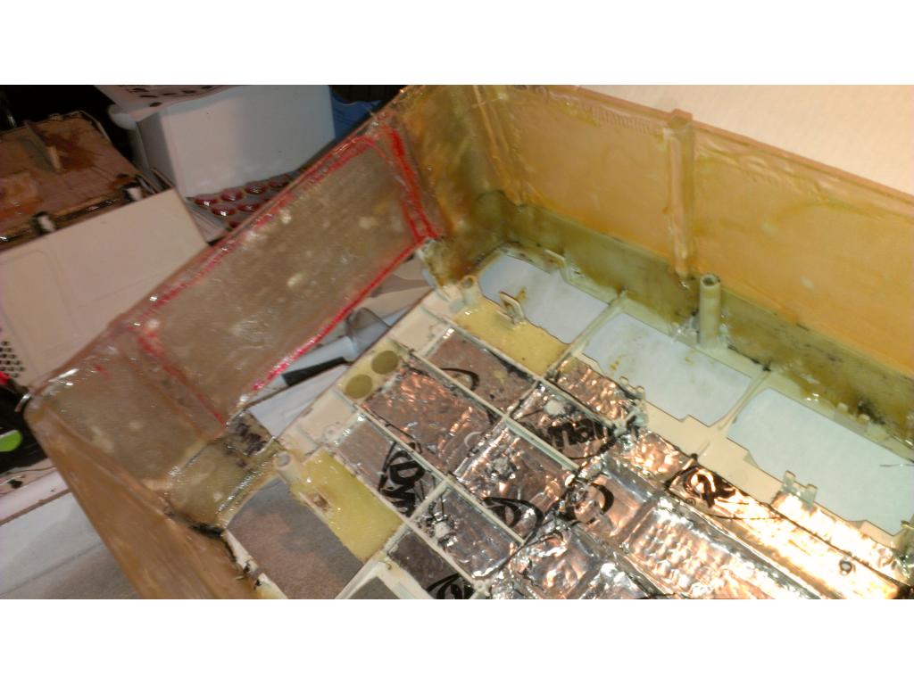
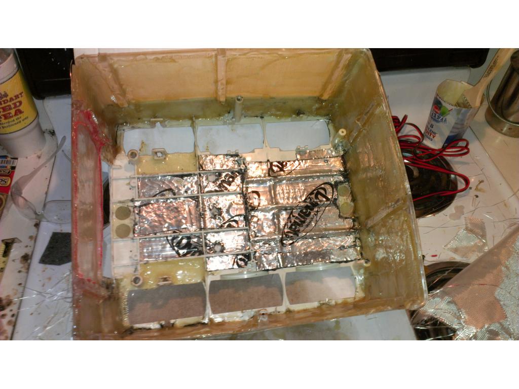
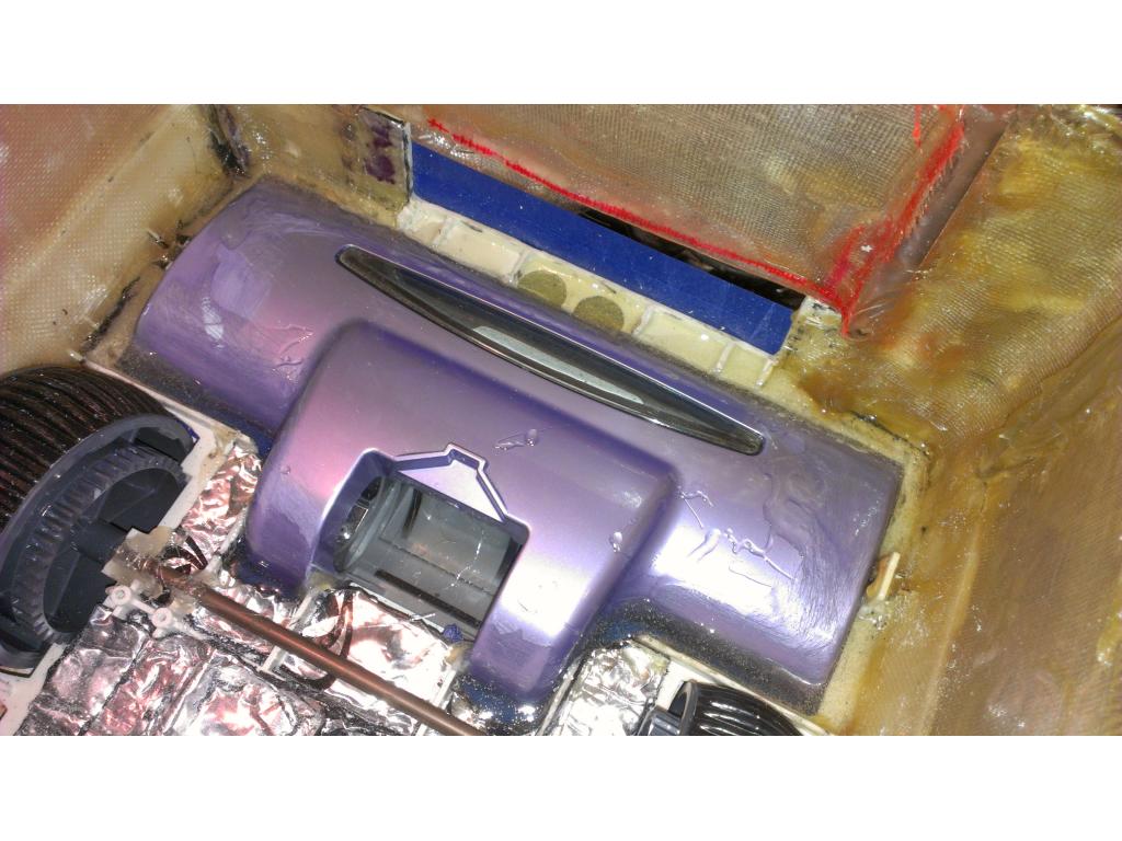
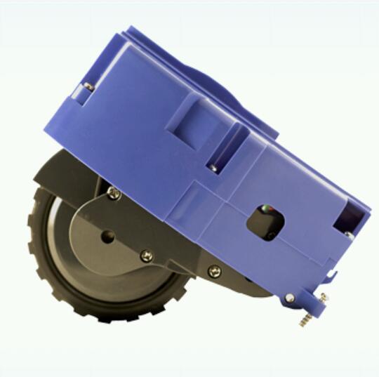
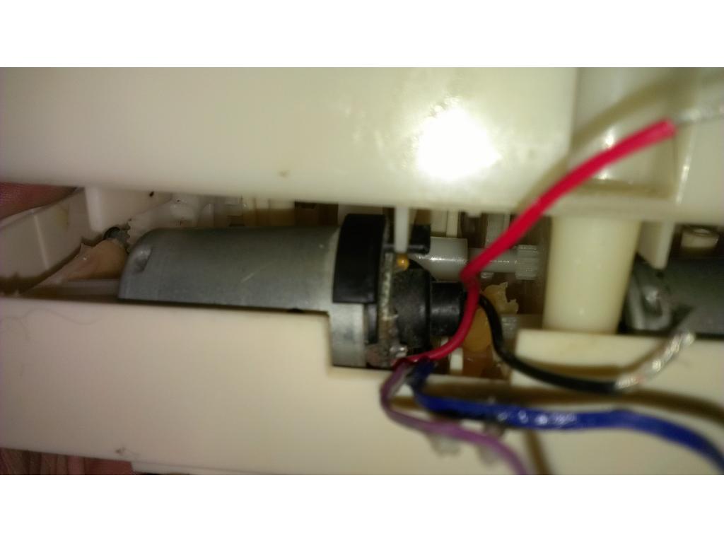
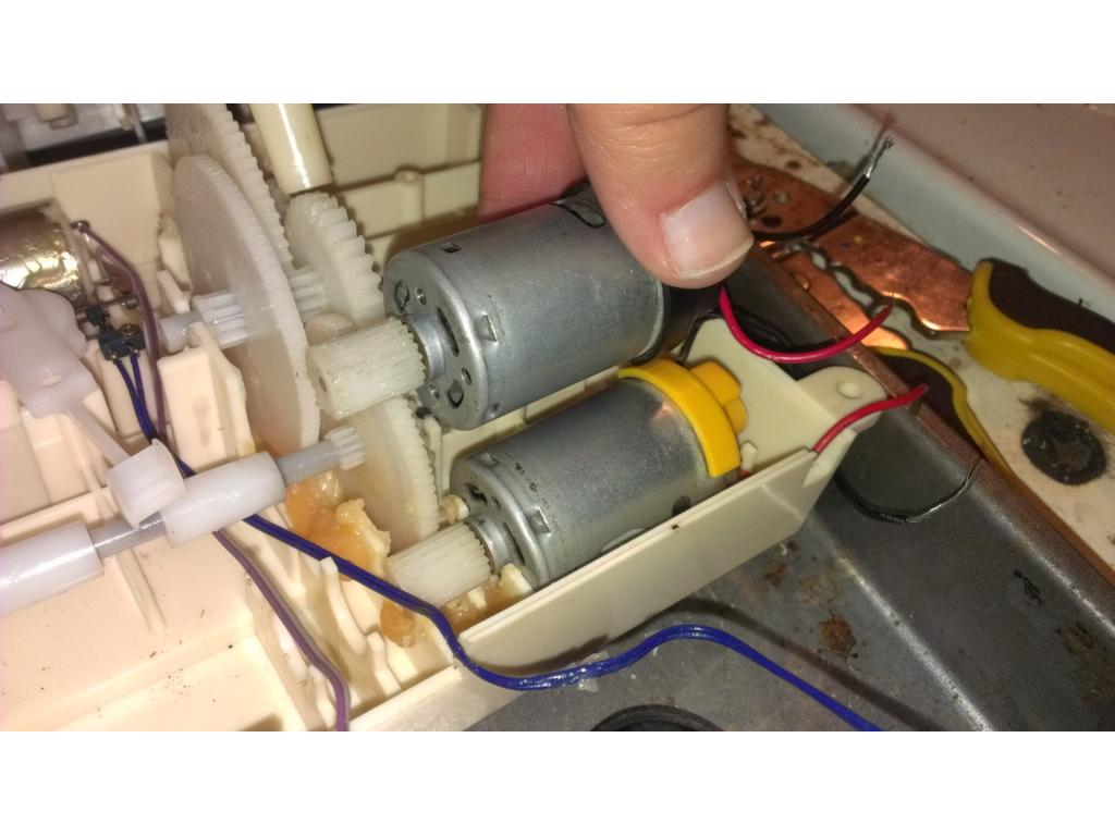
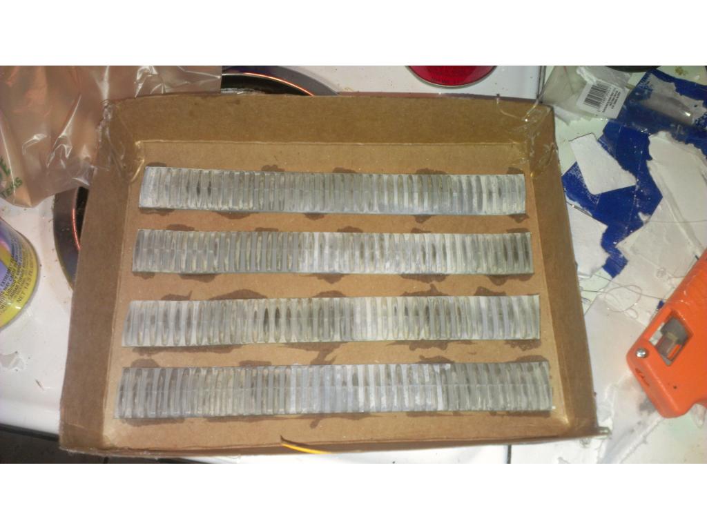
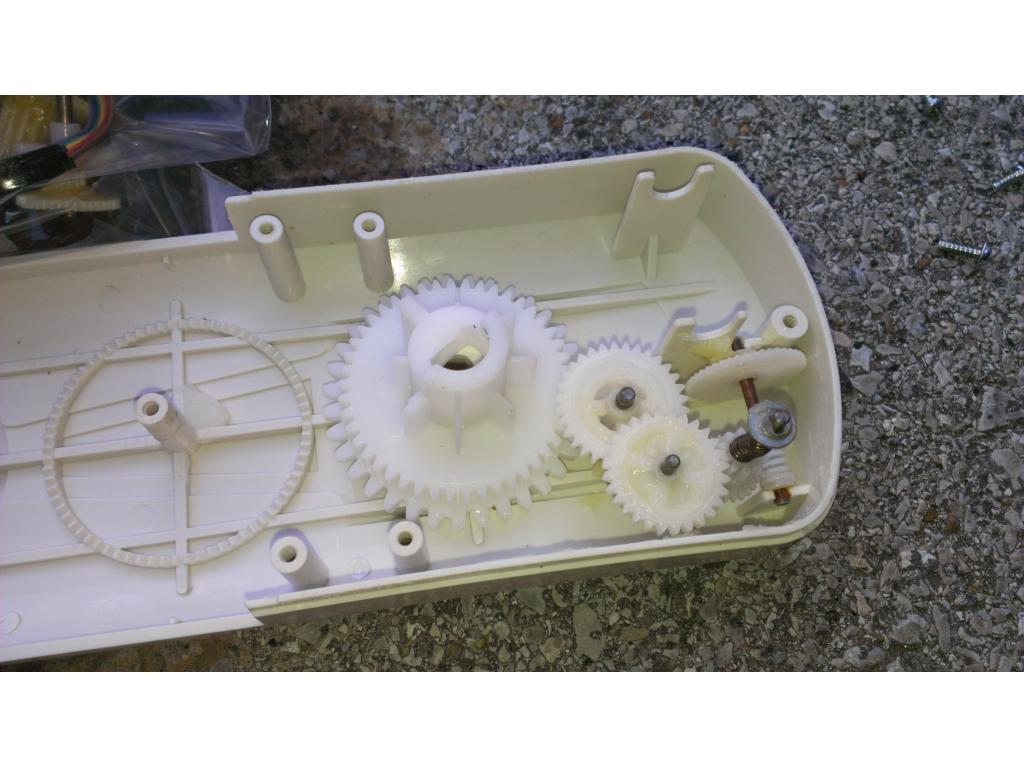
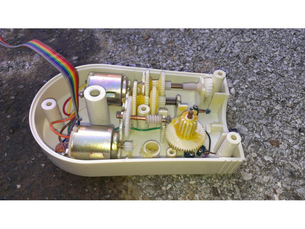
Ok tiny update , batteries on the way , the are 6" L 2.5 W 3.8 tall. They weight 5.9 pounds. So two batteries is 12 pounds , 3 is 18 . I may only install 2 for weight reasons. Also SOUND Deadening is somthing I'm adding in. I'm trying a spray in deadening liner. This is common in high end car audio to block road and wind noise. I'm thinking I could coat the outside of the motor housing and inside where there is no moving parts , and outside all over bottom and top of the gearbox casing. The inside the the bottom half of omnibot would all be coated and inside of torso. Hopefully I can dampen most motor and servo wining! I'm going to take a look at gear housing , if I can fill the gear box area 1/3 with a "gear oil " which is fairly thick ill do that , I believe the bottom of the case is sealed , trick is not putting too much in so the motor itself isn't submerged , this will silence the gears some and add lubrication this little guy hasn't seen in 26 years. . There is a gear switcher for the transmission which I may replace with a servo but it has a "low speed high torque" setting which may be useful for vacuuming or toting around 10th extra pounds of batteries it didn't originally have..
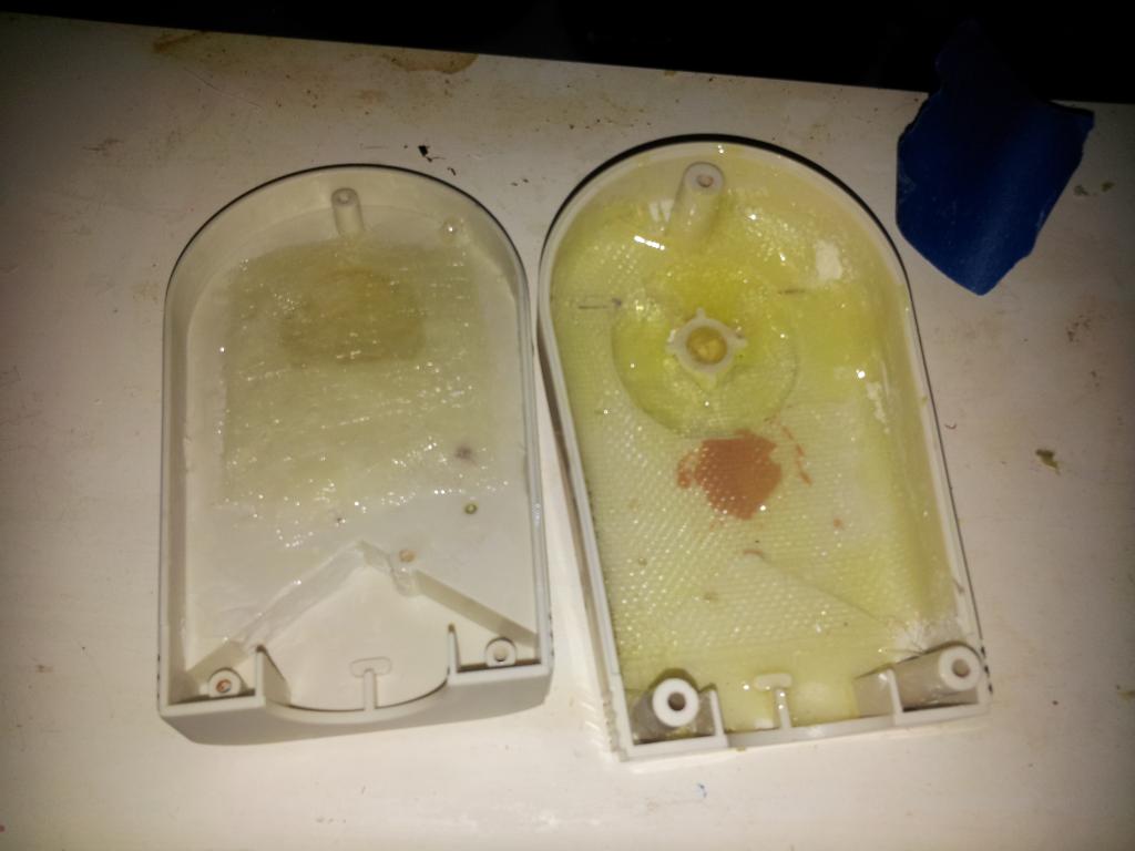
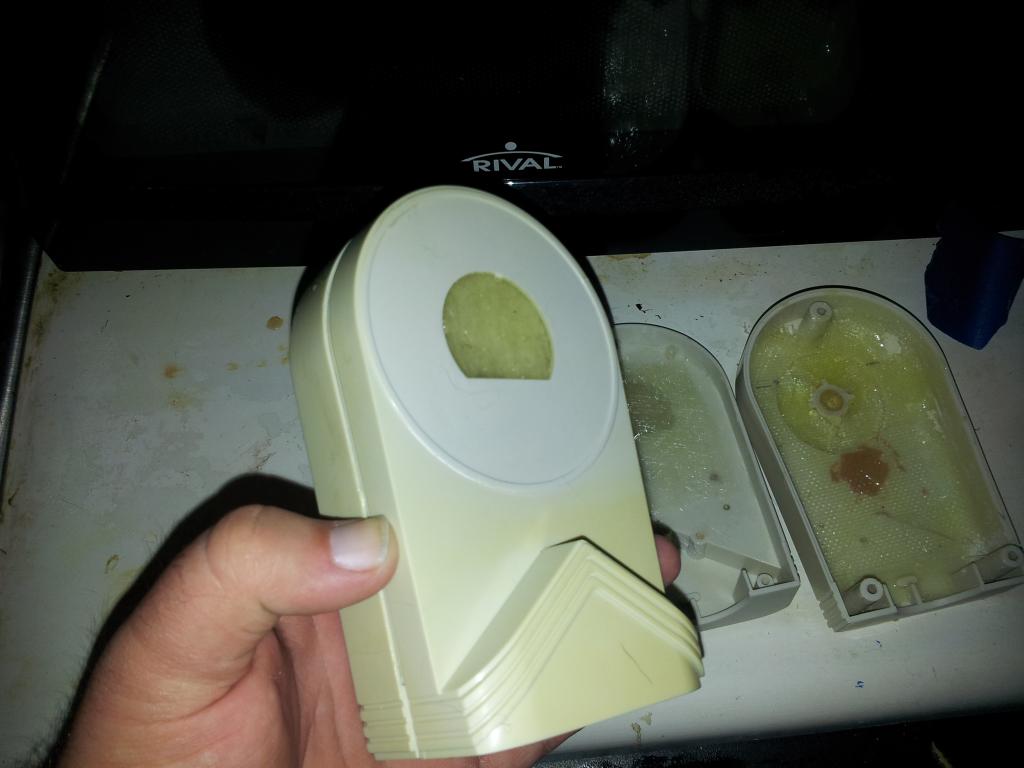
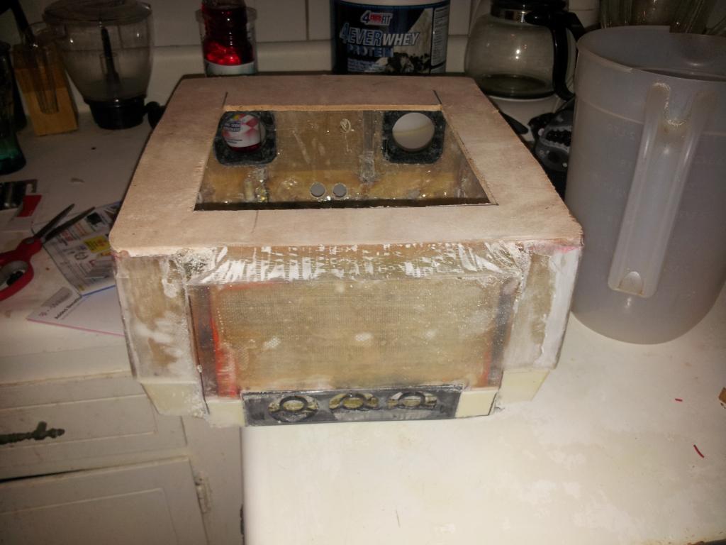
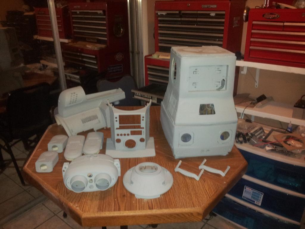
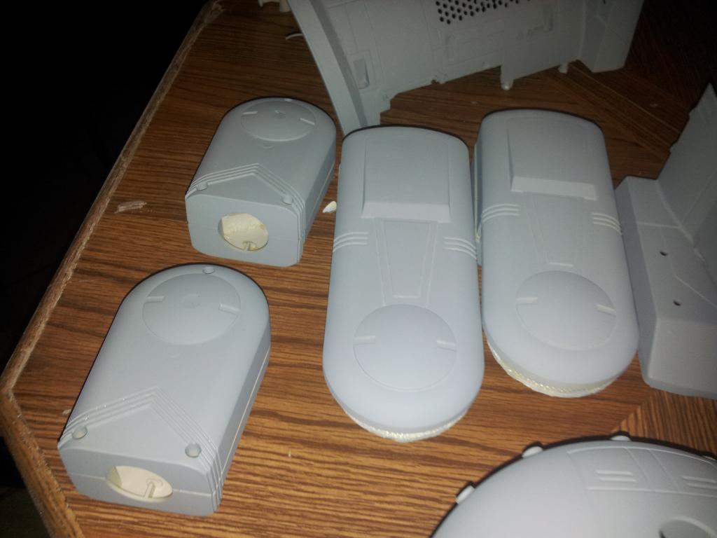
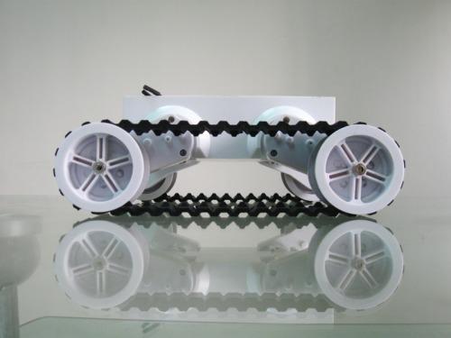
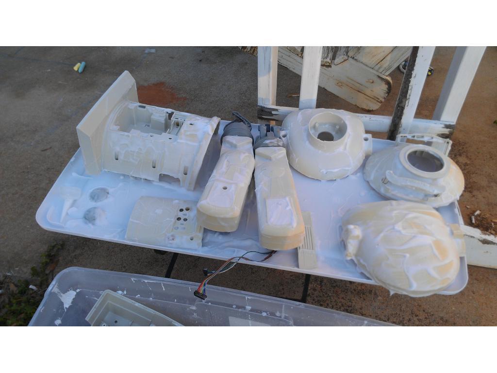
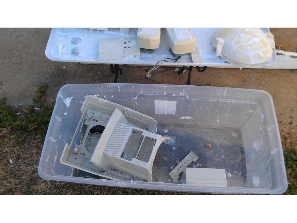
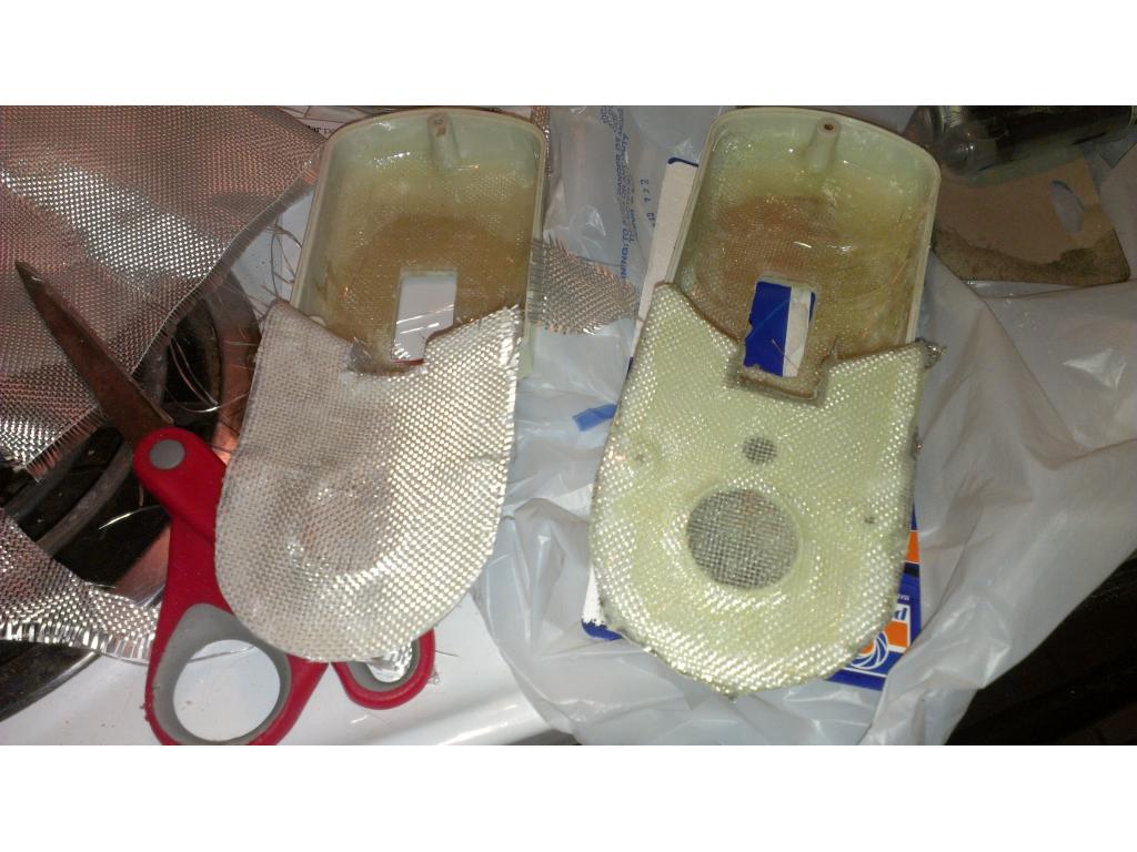
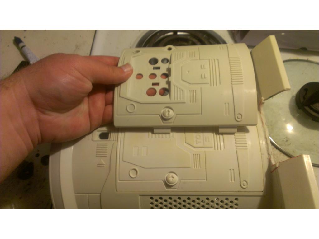
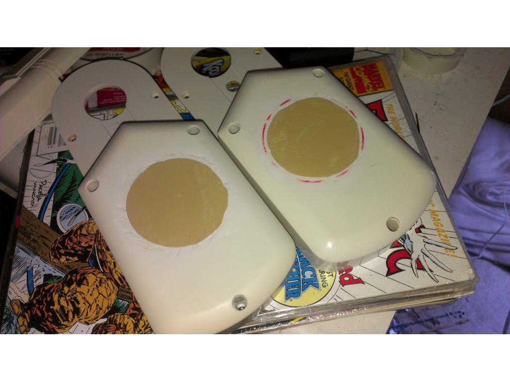
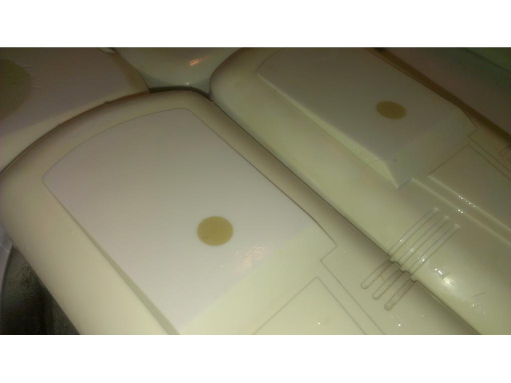
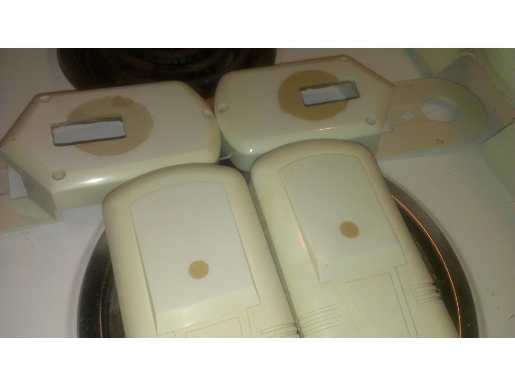
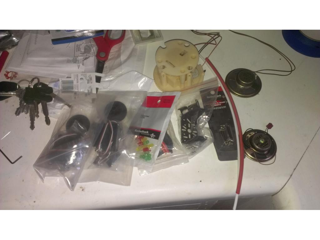
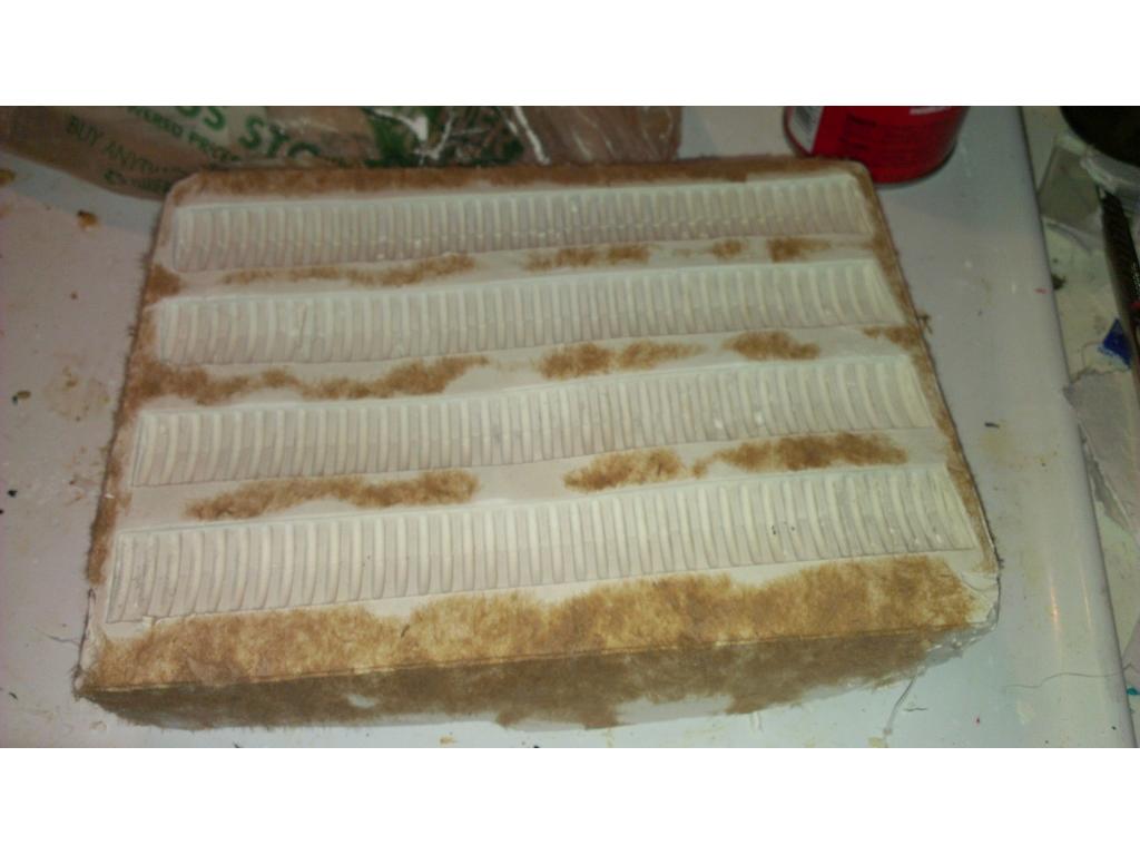
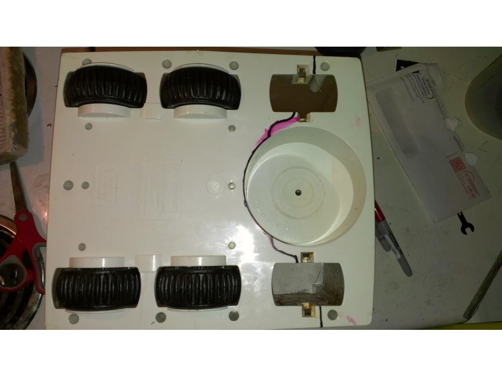
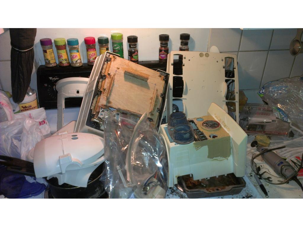
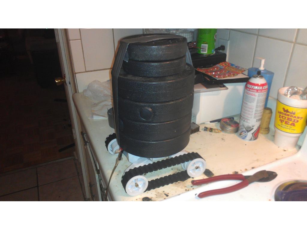
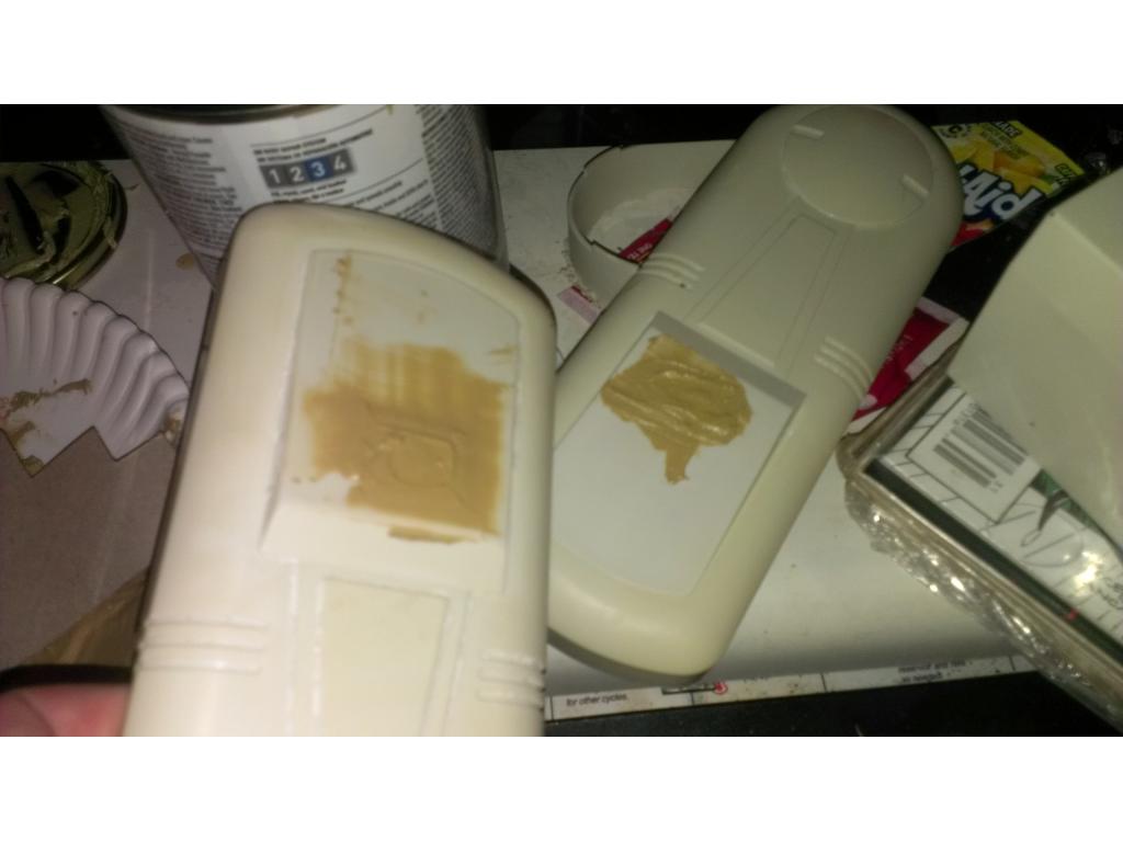
Clearly I've been playing lol. Here's pics of parts after a day of cleaning , the best results appeared after 7 runs through the dishwasher.
Dude, that looks sick sitting on those tracks! I love it!
Thanks , still wieghing options , on a pos note you could do this on your omnibot ! Tracks would be perfect for your bot! I believe you have a rad right? They are going cheap these days. As you can sew the top of bots head and back are still yellowed a bit but its almost completely clean. Thanks for watching my posts Bret , feedback and ideas are what makes the projects even more creative and exciting.
Agreed that the R.A.D. tracks look quite at home under your Omnibot 2000. cool Nice to know I'll have an alternate option if my Robie Sr's drive is a dud. I also love the embedded PC and the location it's currently mounted. I'd really like to do that for my Robie Sr if I can. Would a little home theater PC (HTPC) running Windows 7 Home Premium be beefy enough, you think? I really want the speech recognition to work and having low power requirements wouldn't hurt either.
That is looking really sweet. Love your plans for onboard ITX Mobo! I am very interested on your take of the track drive train. How much voltage are you going to supply to it. Right now I am giving my RAD 7.2 volts and even in low gear mode it moves along pretty fast. I may cut the voltage in half making two low and two high speeds....not sure yet. As far as sound goes. My wife will back me up on this. RAD tracks are LOUD! The gearboxes and motors definitely need dampening. Your idea with the gear oil sounds awesome and I will be following this closely as well as your sound dampening ideas.
Looking awesome!
;)
Yes a Asus mini itx is a great option, it draws less than 20 watts and has built in PSU so it just needs its 12v input ( pretty sure that's watt the act adapters rated for at voltage) it has built in WiFi , Bluetooth, hdmi, dual monitor support, ect. There's beefier versions but I wanted the best power for the wattage. The next step up 20 percent faster and has a larger heatsink. They are made to be home theater computers with recording capability, support for 4 data drives , 4gb ddr3 ram and even a PCI express x16 slot for a nicer video card , video capture or whatever. These boards have comparable performance to a 2ghz p4 mobile CPU for 1/4 the wattage and heat. Also it doesn't require enourmous amounts of air to cool because of the larger fanless heatsink.

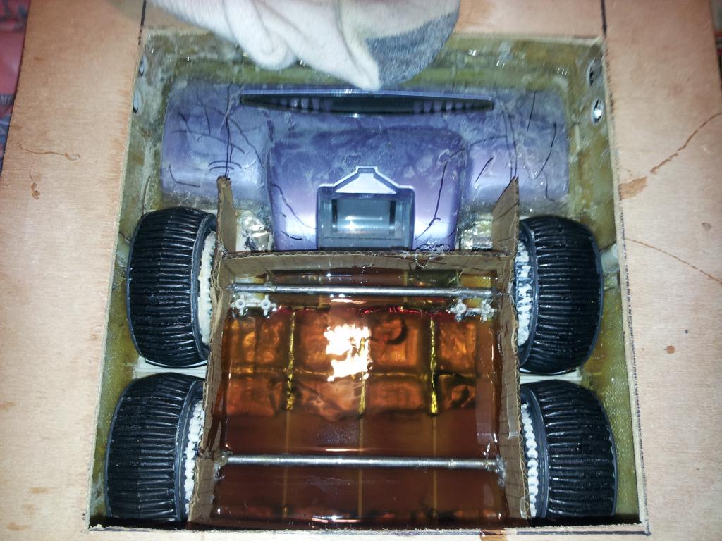
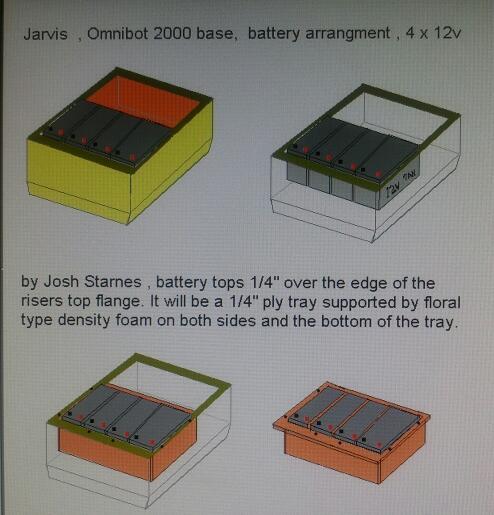
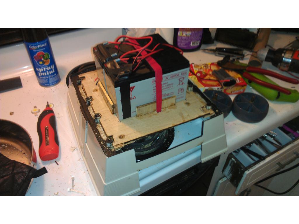
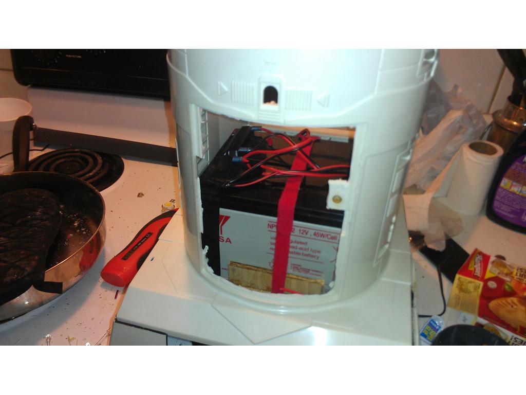
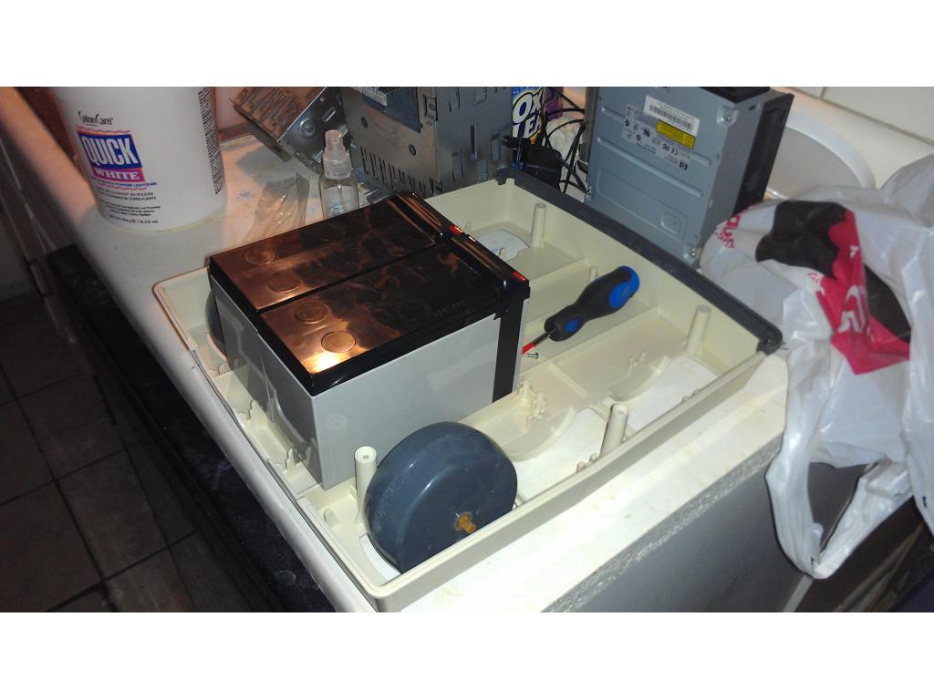
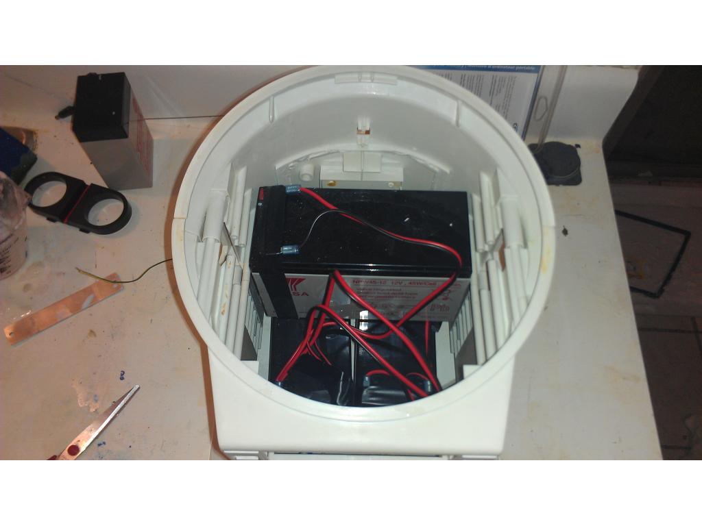
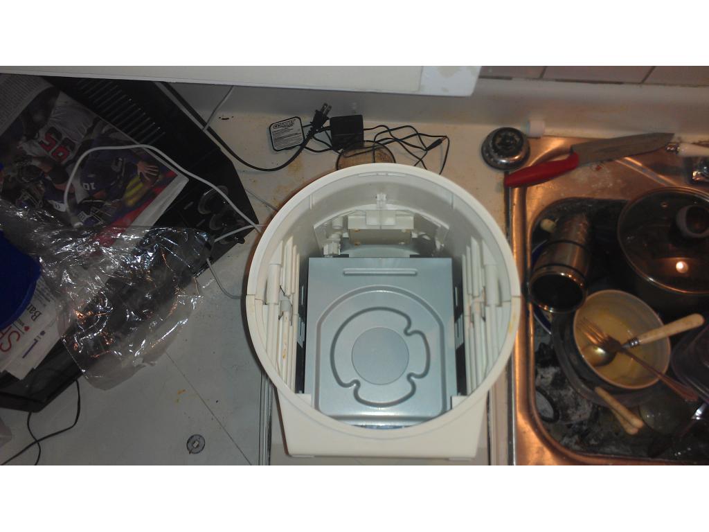
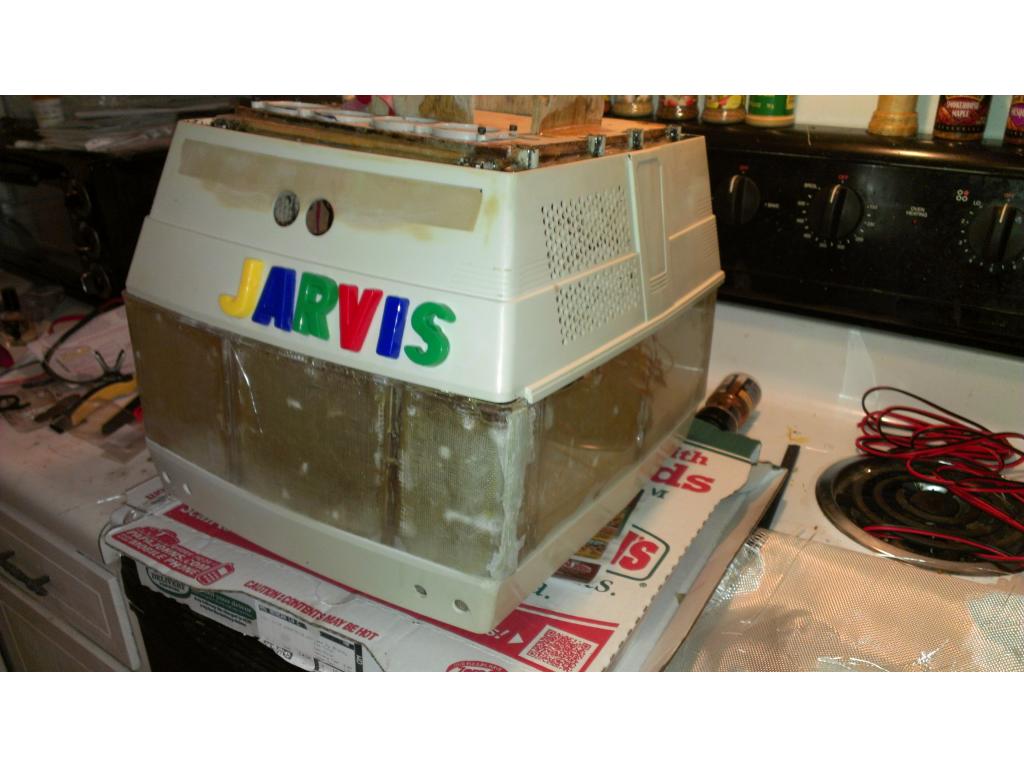
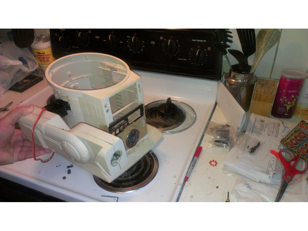
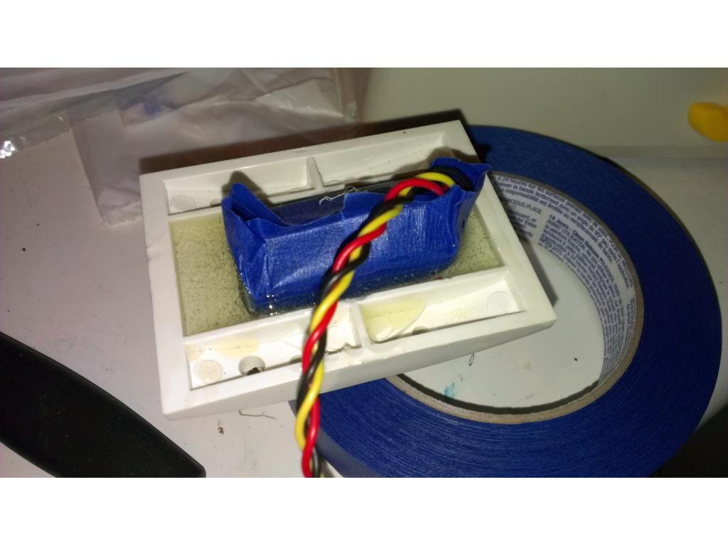
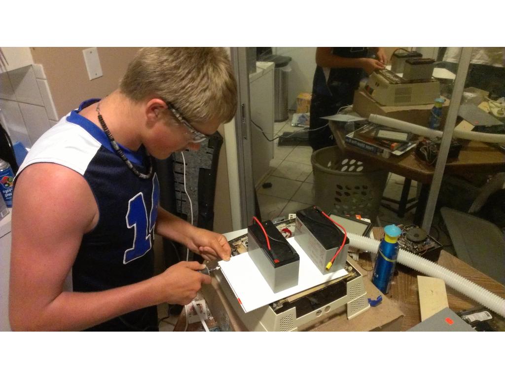
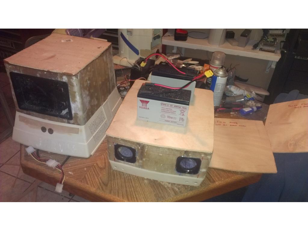
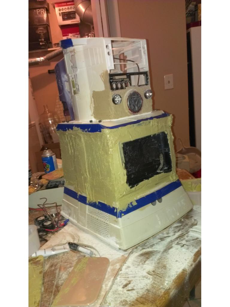
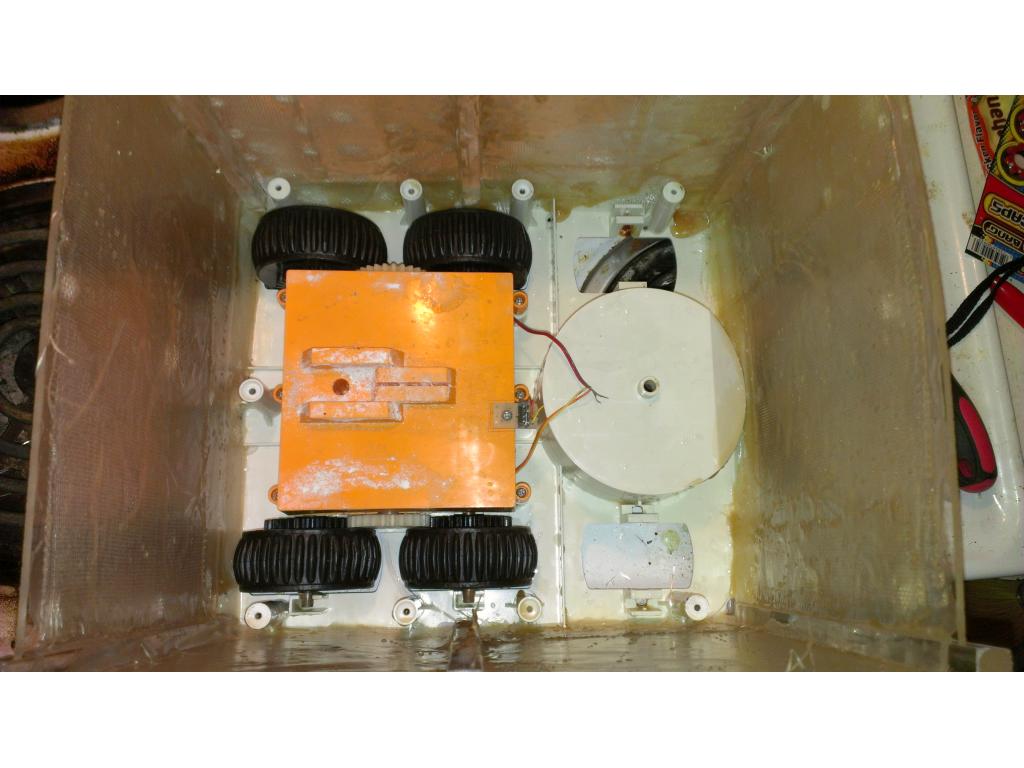
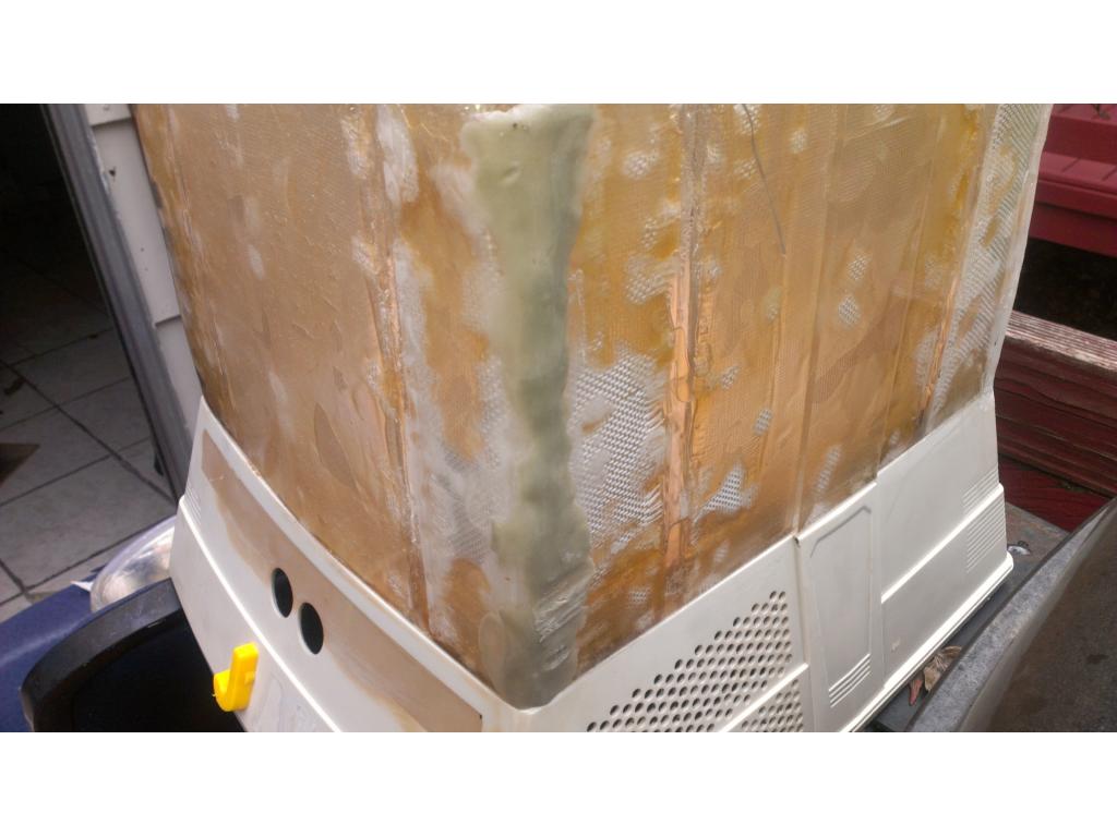
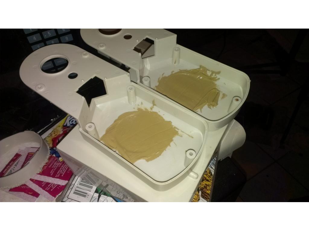
Omnibot gets final bleaching , I used salon 40 lift peroxide and powdered beach mix together to make toothpaste type thickness or little thinner , hit with heatgun , set for 2 hours and then ran through dishwasher.Batteries are here today ! The drawer just so happened to fit one 7 ah battery with no mods. However in the future I would like two or three in the bot. Here's a pick of one and layout for two batteries. Two batt gives me 17ah @ 12v way more than original batt. I'm not worried about tracks till after I get this thing running and ESB in my hand.

I'll do measurements later but I believe a couple batteries could lay ontop of the gearbox as well. After measuring I found that cutting out the AA battery and fuse area on omnibot leaves me with a easy 4th place to mount a 12v 8.5ah battery. This juice hungry monster wouldn't be running to the charger anytime soon with 26ah of juice from four batteries, how crazy would that be! Excellent news is my battery guy gets me 3 batt for 19.99 name brand yusa New! So if anyone needs some lemme knowwyeah, i have an dual core ion for an HTPC right now. Those things work very well. What are you planning to run on it? Are you going to go with the SDK or ARC. I am really liking the added features DJ is putting in for I/O. That way you can leverage all the cool controls and easy scripting DJ has in ARC but also send/receive using the TELNET/Web interface. That opens you up to using programs like Autohotkey and Eventghost to automate other processes that are not currently in the ARC realm. For examply if you wanted to tie this into your caller ID system. you can do it and have your bot speak who is calling or read to you the latest news feeds when you ask it. Looks like you are moving along well with your project. Thanks for the connection on the batteries..I may take you up on that at some point.
Kevin
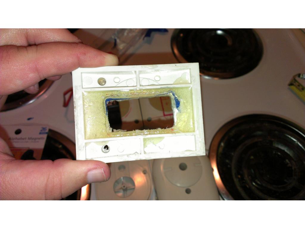
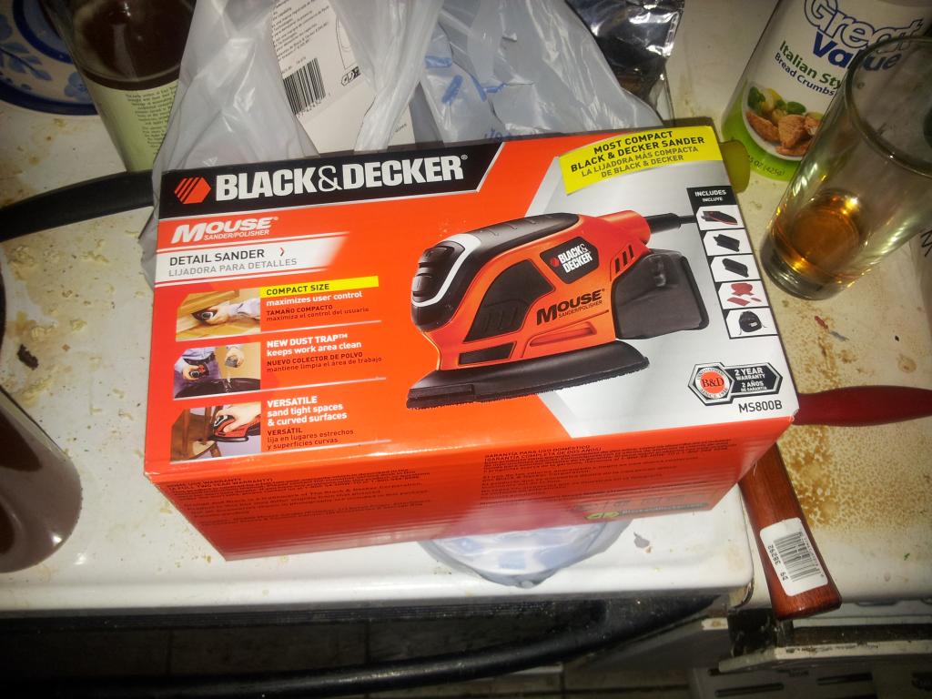
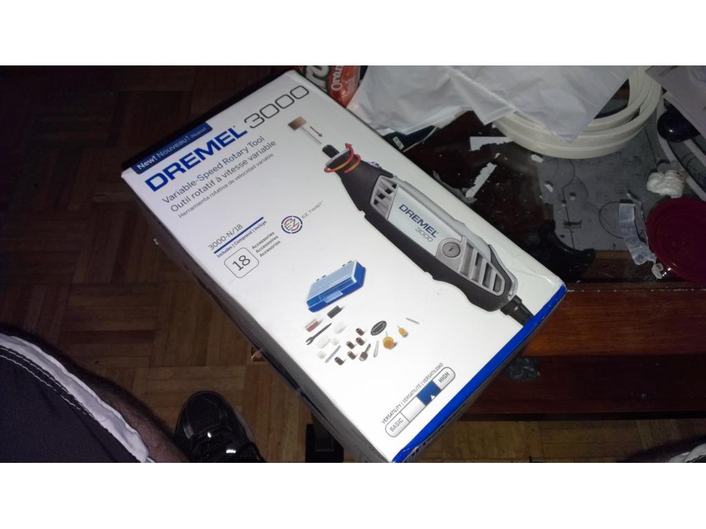
Thanks for feedback Kevin! Ironically I feel like I haven't done anything! Lol I cleaned the bot the last time so I'm ready for some cutting! My favorite tools are my Kawasaki and dremel brand rotary tools. Not only will this.be.a.robot but its gonna be my grove with.blueray player. I don't know anything about the interfaces yet but ARC sounds easier at first. I basically plan to put a nice touch screen fan controller in the chest and blueray drive but I need to trim up some plastic as I need another 2mm on each side to fit. I though about mounting drives on front of the.base above the.gearbox too but first things first! Mounting the motherboard upside down in the motor compartment and cutting the rectangle hole out of the insert behind the accessory door so I can flip up the acc door to cover pc connections when mobile/autonomous. I will only use super quiet rated. Fans , like 30 dba then ill use the fan controller to reduce their.voltage till they are 20 to 25 dba so I can't.hear fan buzzing as it cools ez board or.HTPC inside.
ASUS DELUXE HTPC MOBO FROM NEWEGG.COM
http://www.newegg.com/Product/Product.aspx?Item=N82E16813131635R
PCI Express x16
SATA
Onboard Video Chipse
Wireless LAN
Bluetooth
PS/2
Video Ports
HDMI
USB 1.1/2.0
S/PDIF Out
Audio Ports
Onboard USB
Form Factor
Dimensions
Features
Learn more about the ASUS AT3IONT-I Deluxe
ASUS
AT3IONT-I Deluxe
Motherboard/CPU Combo
Intel Atom 330
Yes
Intel Atom
533MHz
NVIDIA ION
2×240pin
DDR3 1066/800
4GB
Dual Channel
1
4 x SATA 3.0Gb/s
NVIDIA ION
Realtek ALC887
6 Channels
10/100/1000Mbps
WiFi IEEE 802.11b/g/n
Yes
1
D-Sub
1 x HDMI
6 x USB 2.0
1 x Optical
1 x 2-CH RCA AUDIO 6 -Channel Audio I/O
2 x USB connectors support additional 4 USB ports
Mini ITX
6.7" x 6.7"
Intel Atom 330 on board Nvidia ION Graphics Processors Home Theater Gate WiFi 802.11b/g/n and BlueTooth Wireless on board DC on board Remote Controller & Receiver
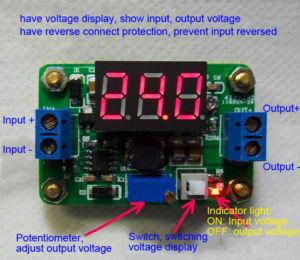
@ KEVIN I plan on testing drive motors at 12v and then scaling them back with adjustable voltage controllers , I will turn it back from 12v till the motors are more quiet but still can pull the bot around fine. This voltage stepdown would reduce current draw over running it wide open at 12v. It would be nice to drop it to 5 to 6 volts but that really must be tested, lowering voltage is a proven way to lower sound and saves battery too . At first I will use the omnibot drive which already runs at 6 volts maybe I can lower it to around 4 - 4.5v and the bot still scoot around fine.
@jstane1 Be careful driving the RAD motors at 12V. You don't want to burn them out. Stock they were driven at 6V. I am pushing 7.2V to them and they seem fine. Not sure I would drive them to 12V..maybe for testing. At 12V if they don't burn out, they will turn the gear box even in low gear very fast. Just a caution when you start testing. If you have another power source, you could check it out at 6-8V first before hooking up 12V. I would not want you to burn the motors out. I would probably say that is the same for the Omnibot motors too...especially if they were stock at 6V.
Good luck! Thanks for posting the specs on your mobo.
v/r
kevin
Thx for feedback , checking YouTube there are.others running 12v on rad and omni but when I meant starting at 12v and testing I was reffering to the battery I was using being 12v not that being the voltage I put to them , I rather undervolt to 5 volt if I can. Can you try under volting yours and see if it significantly affected it?

Okay I coated all of the bot especially the problem areas with 15 percent hydrogen peroxide , and I'm rinsing that after 2 hours then adding more and let it sit overnight , then tommorow am I will recover the parts in solution and let it sit for a few hrs in the sun.@ Kevin you definitely gotta tell me how to get my personal robot to read feeds and messages. There are text to speech air programs out there that some trendy websites are using that allow the bot to literally have a conversation but that's on a webpage I don't know if that could translate to use with the robot. First thing I gotta figure out is how this guy will charge. I was watching a 90s movie called evolver that was basically a autonomous laser tag enemy but he charged literally seeing a regular 110 volt outlet and plugging his arm in that had a power plug on it. Copying the way roomba does it wouldn't be bad either.
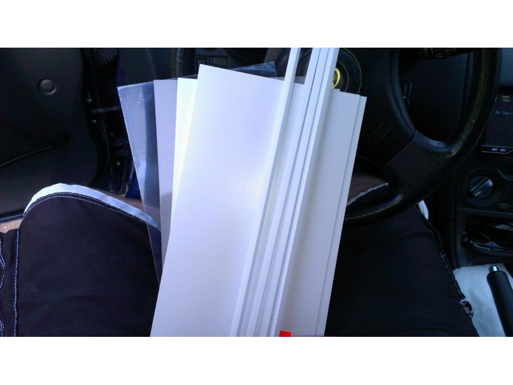
Alright some parts came in. I have 4 sheets of dynamat come in still waiting on two more. The ez board kit came in today! I have HDD mounting bracket and cooling fans. Just waiting on my fan controller , motherboard and CPU. I sold the Asus theater pc board on eBay and reined around to buy a nice one with am3+ AMD socket with 8gb ram support still mini itx form factor. The board I had was 20w CPU power consumption so I am being careful to get the most performance from a processor and keep it 45 watts tdp or less. I found a dual core Athlon x2 25w 2ghz I'm considering but there's a 3ghz version that uses 45watts. So I'm tossing between these two performance vs my bots autonomous battery life.
Nice
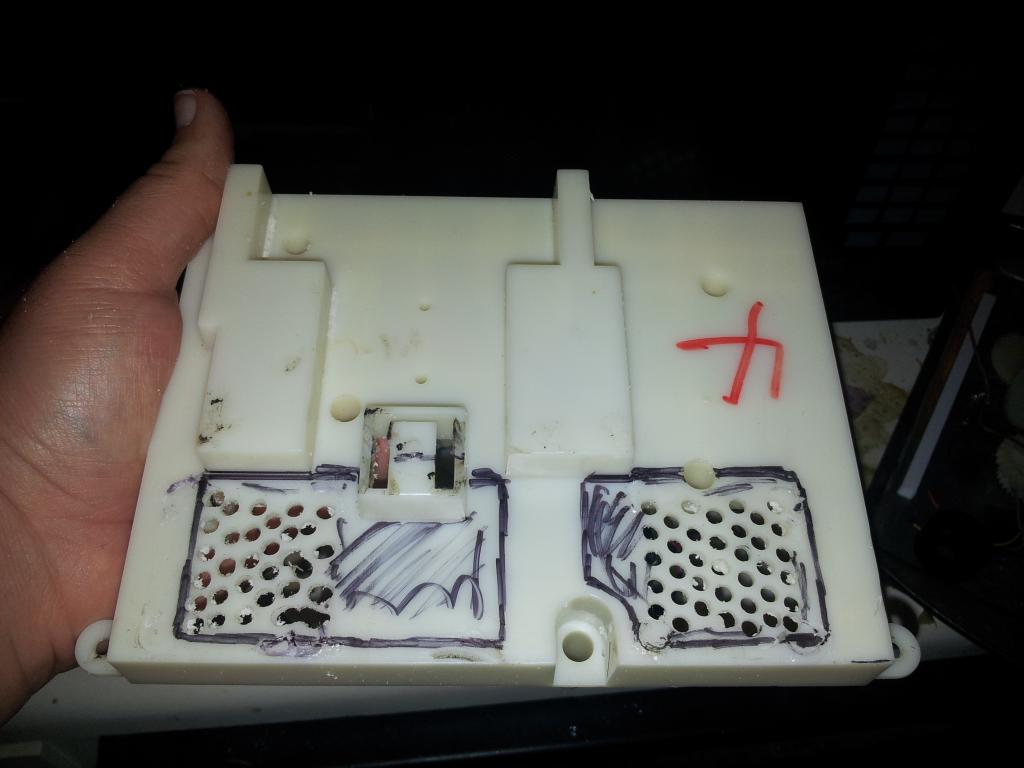
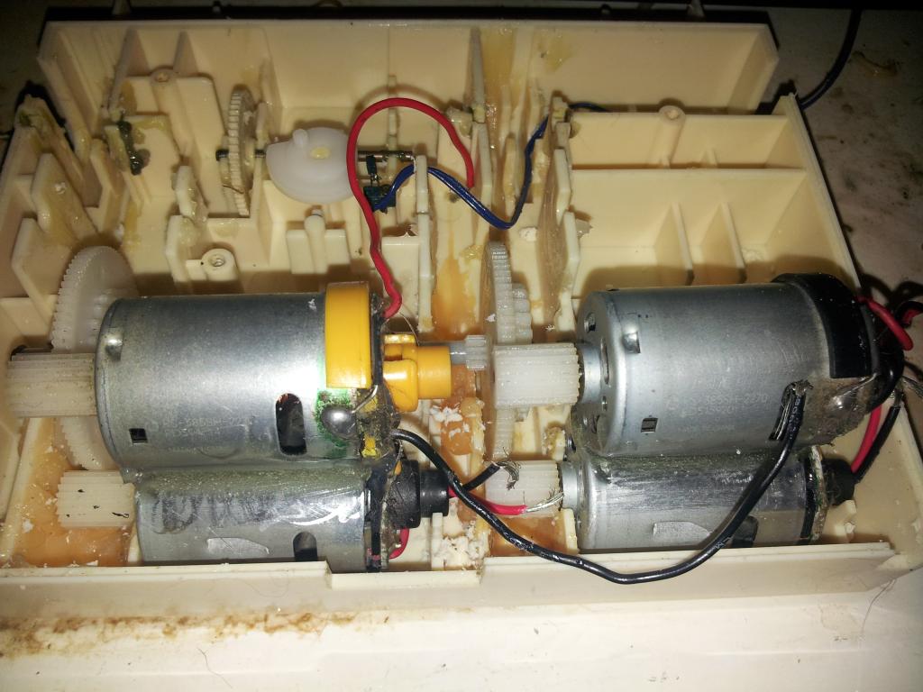
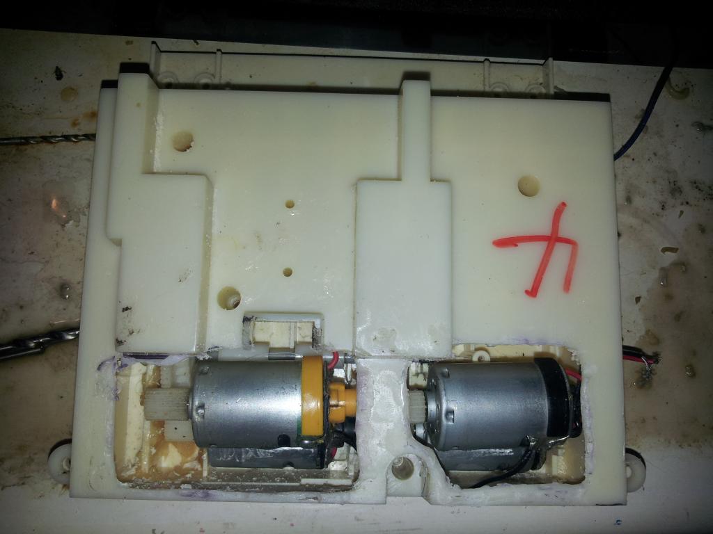
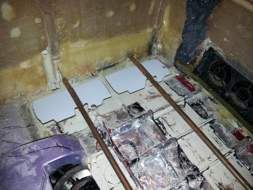
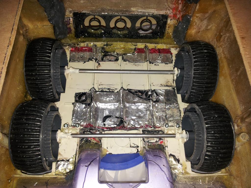
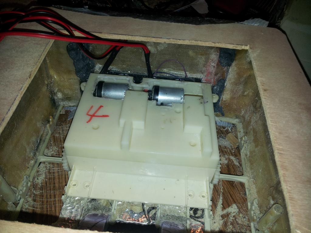
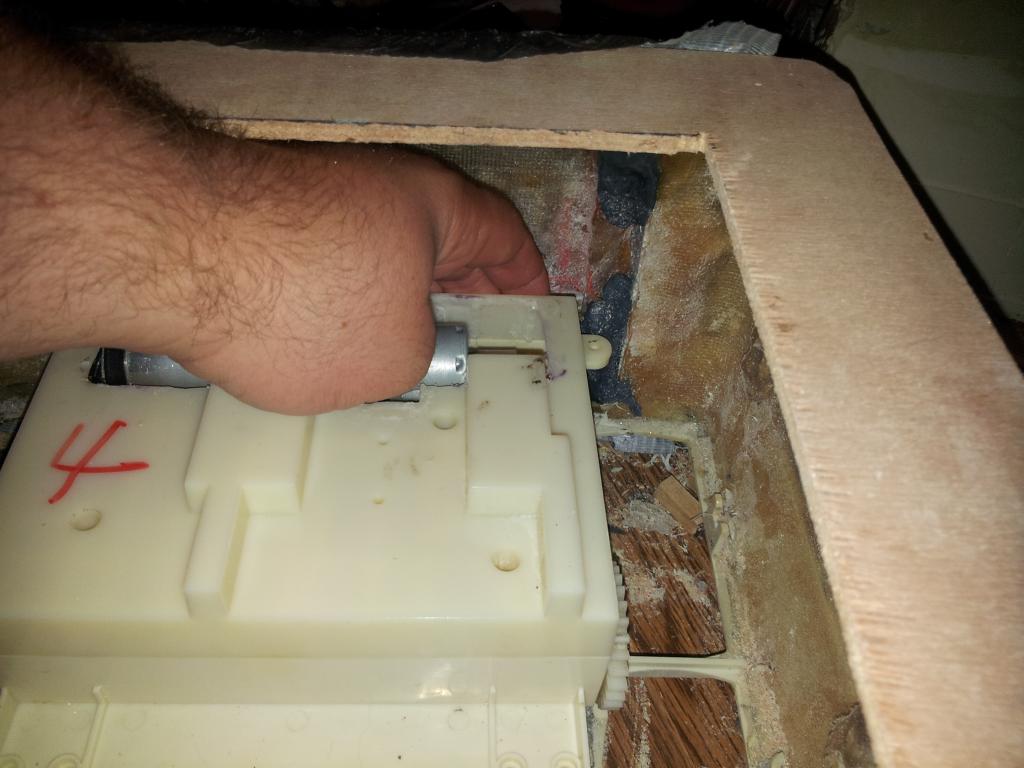
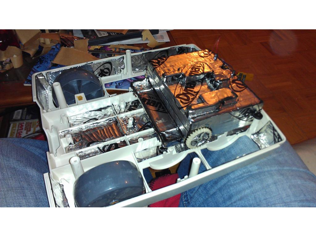
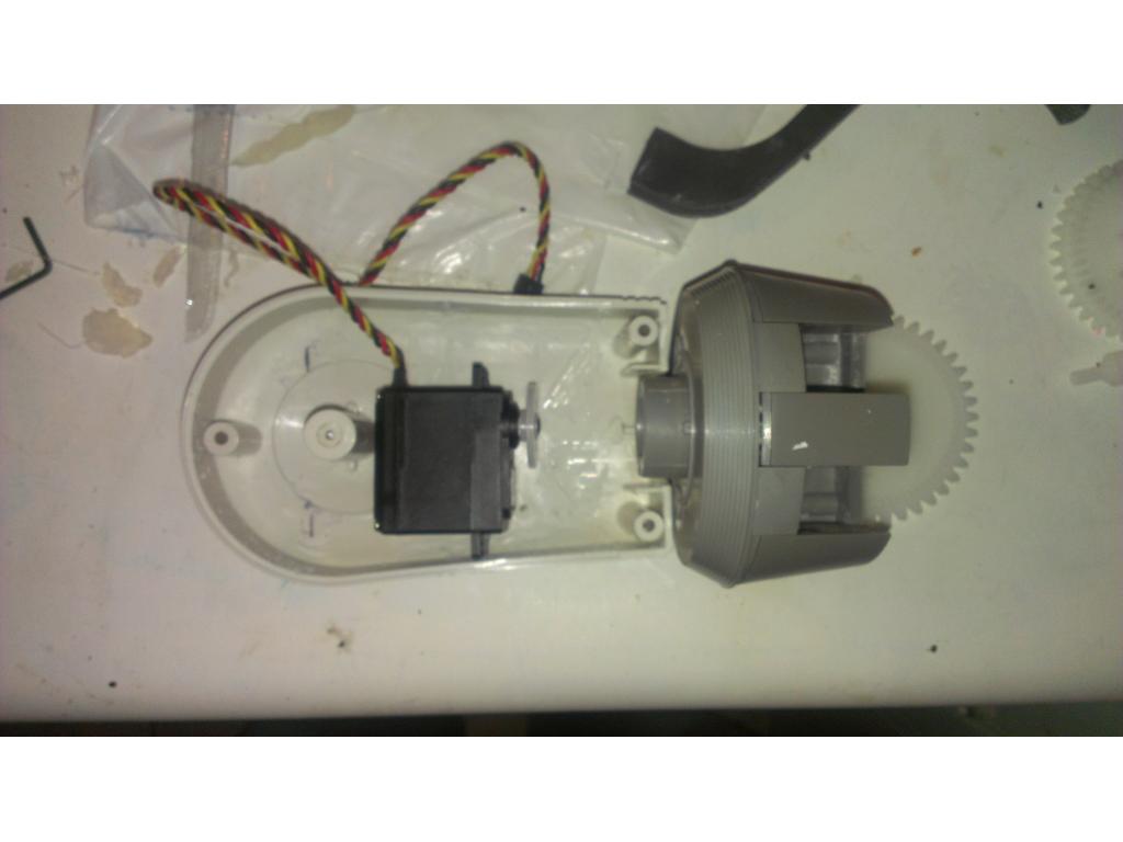
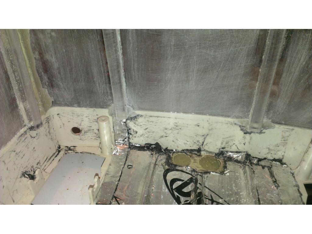
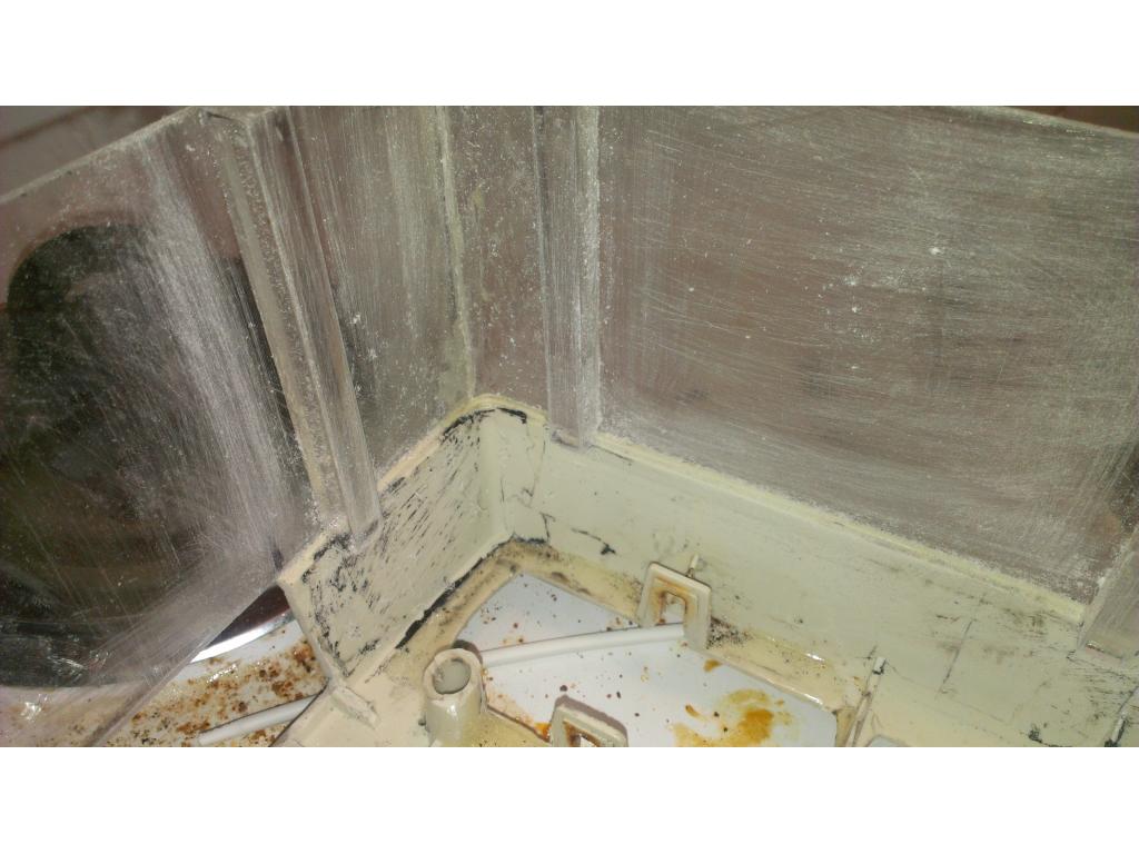
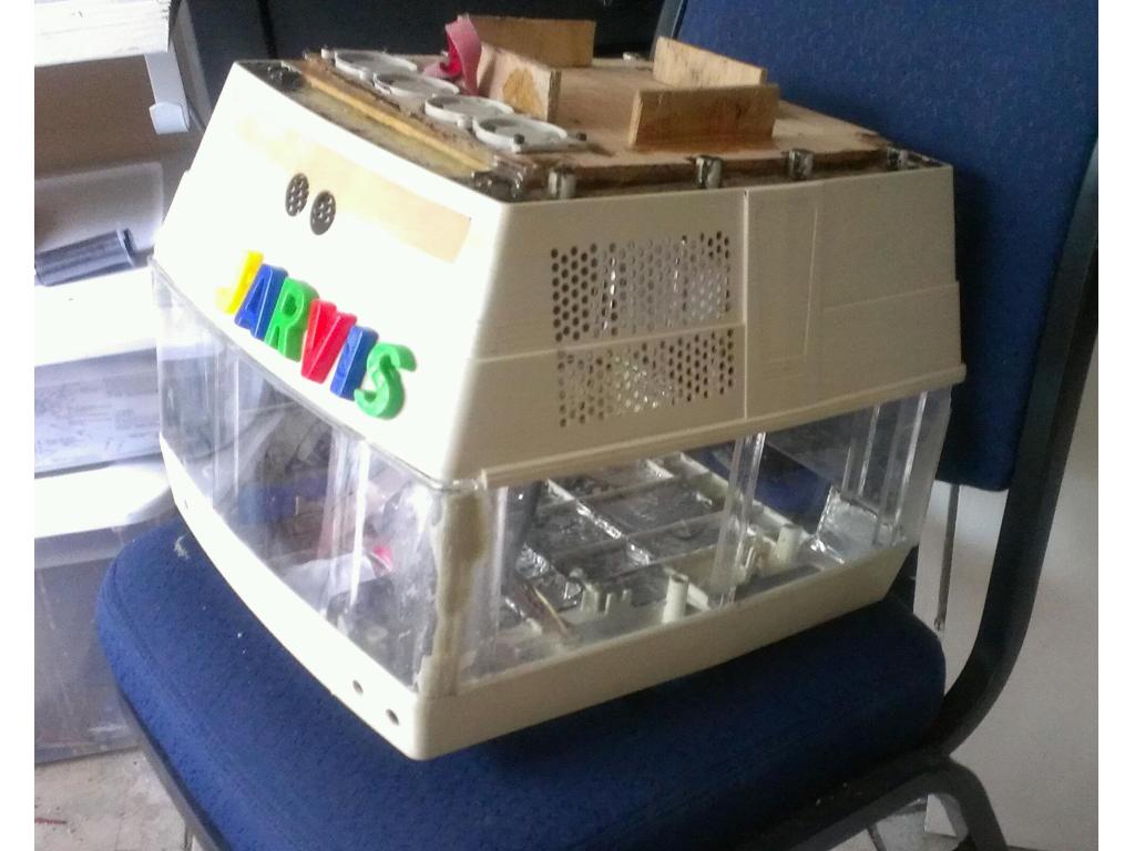
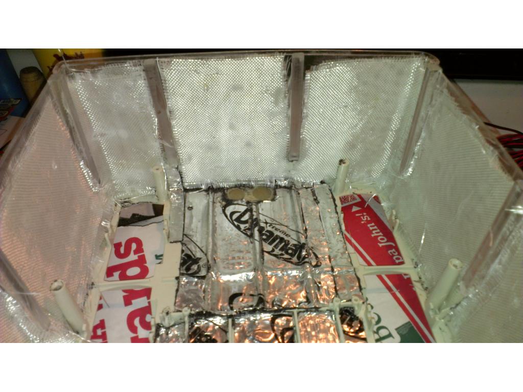
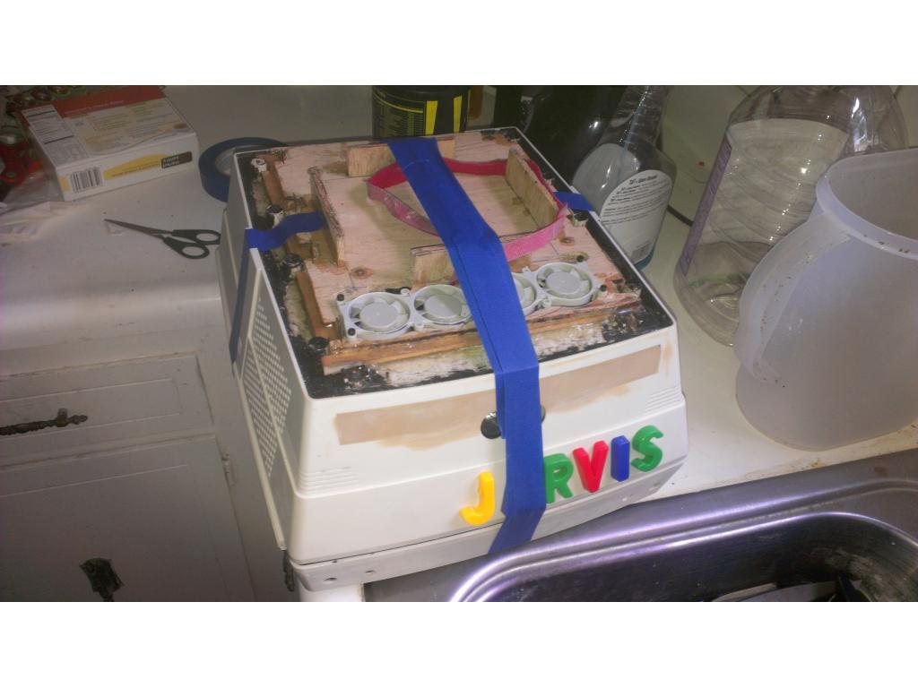
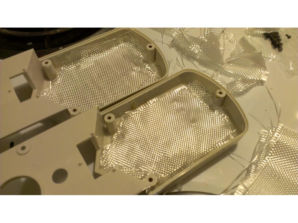
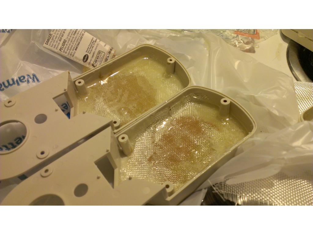
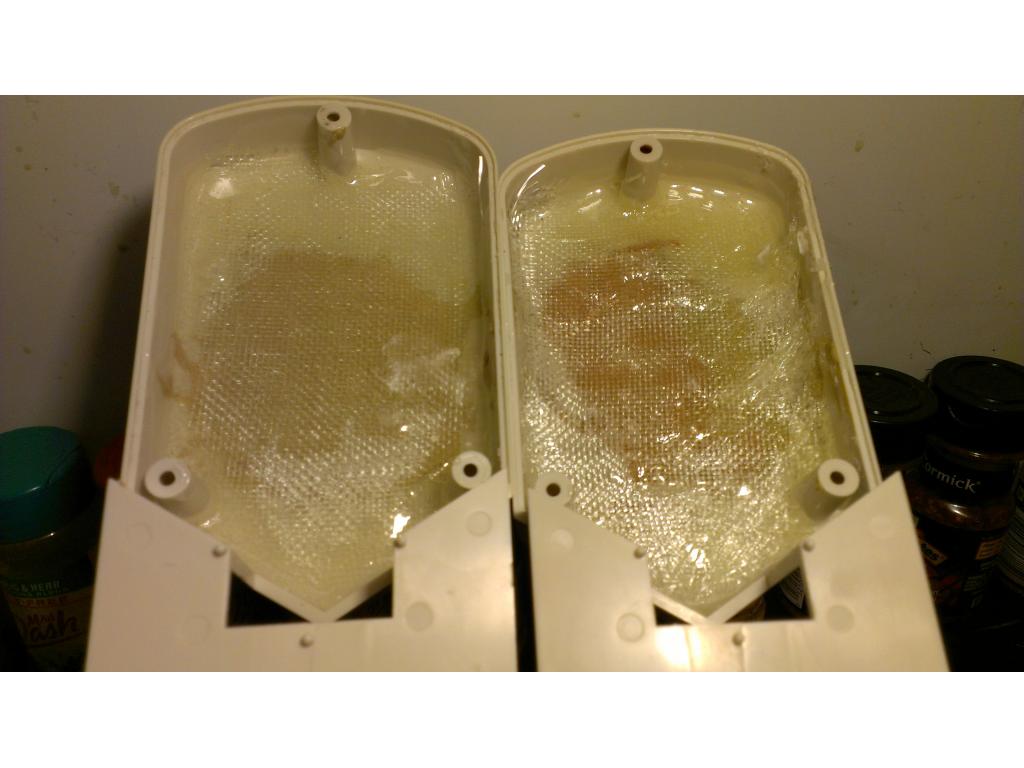
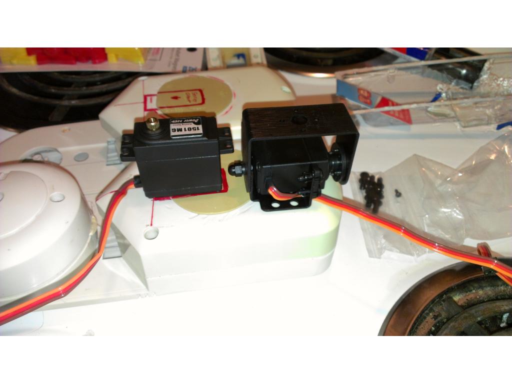
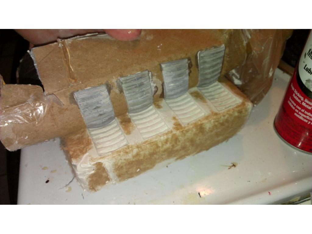
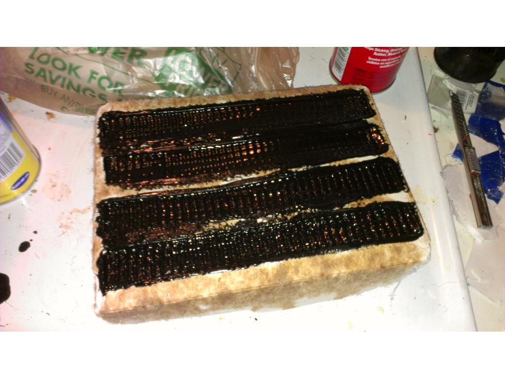
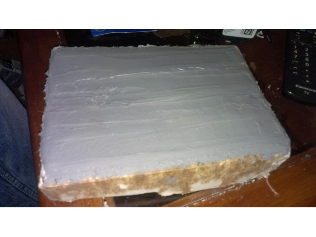
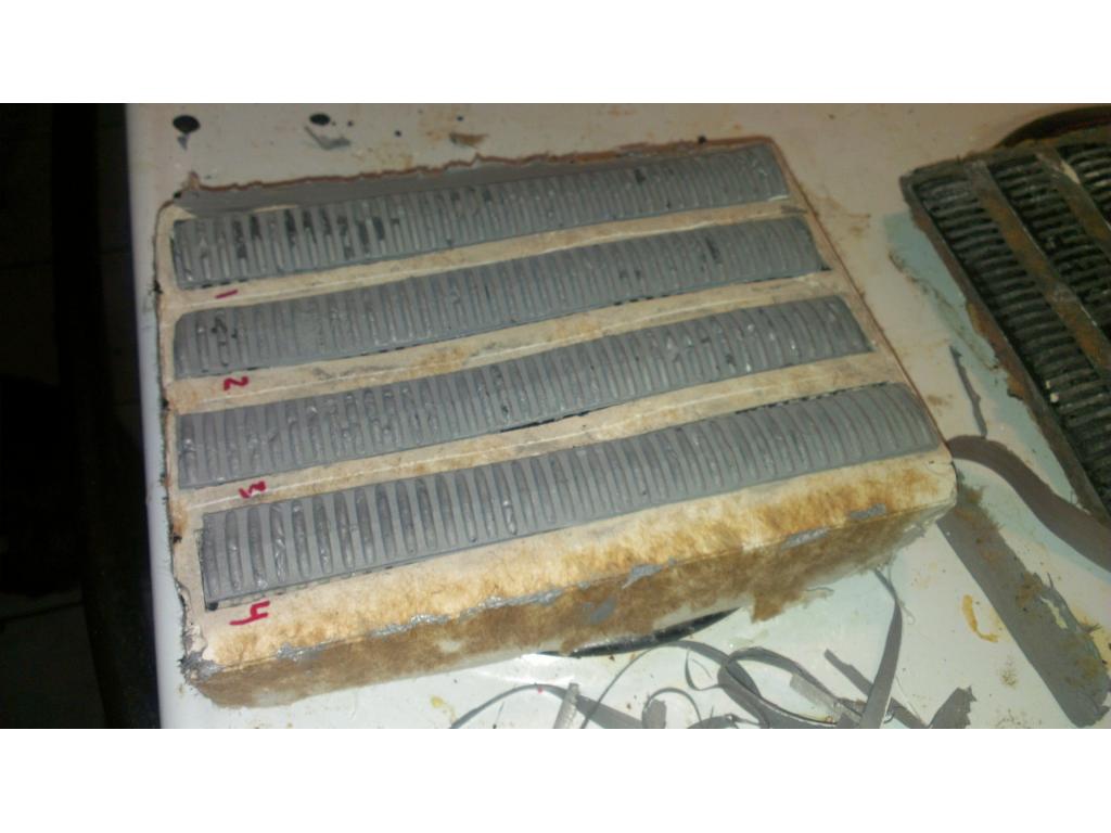
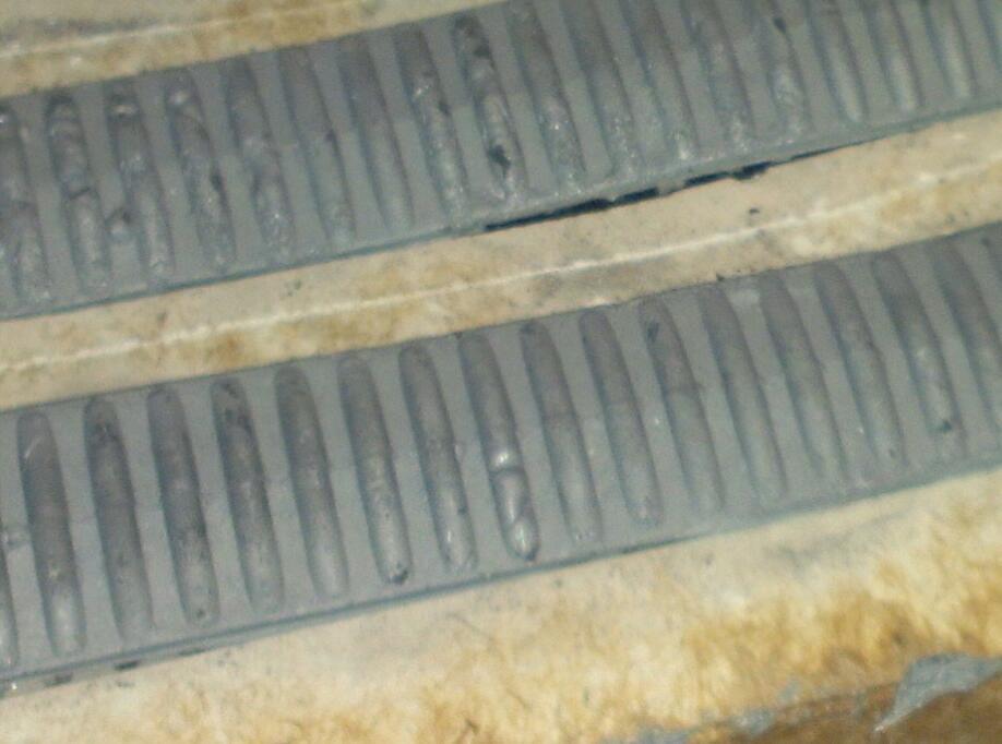
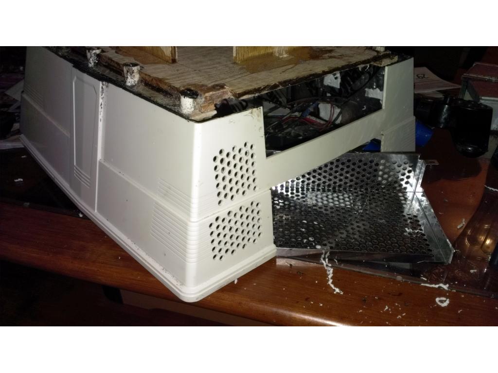
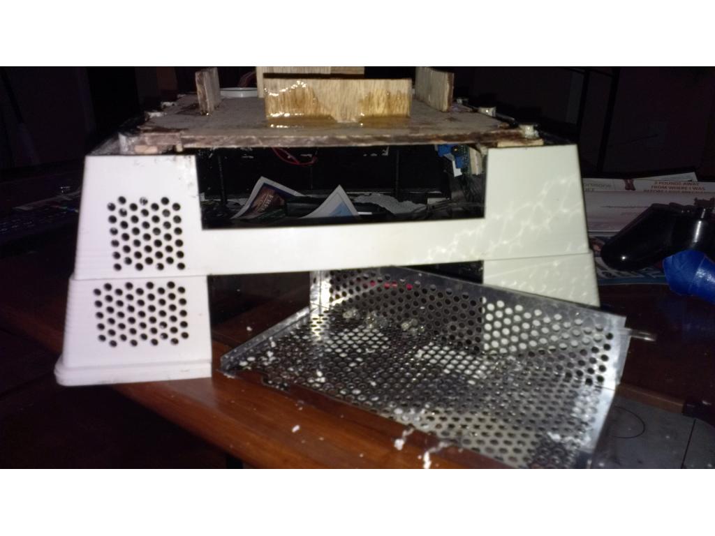
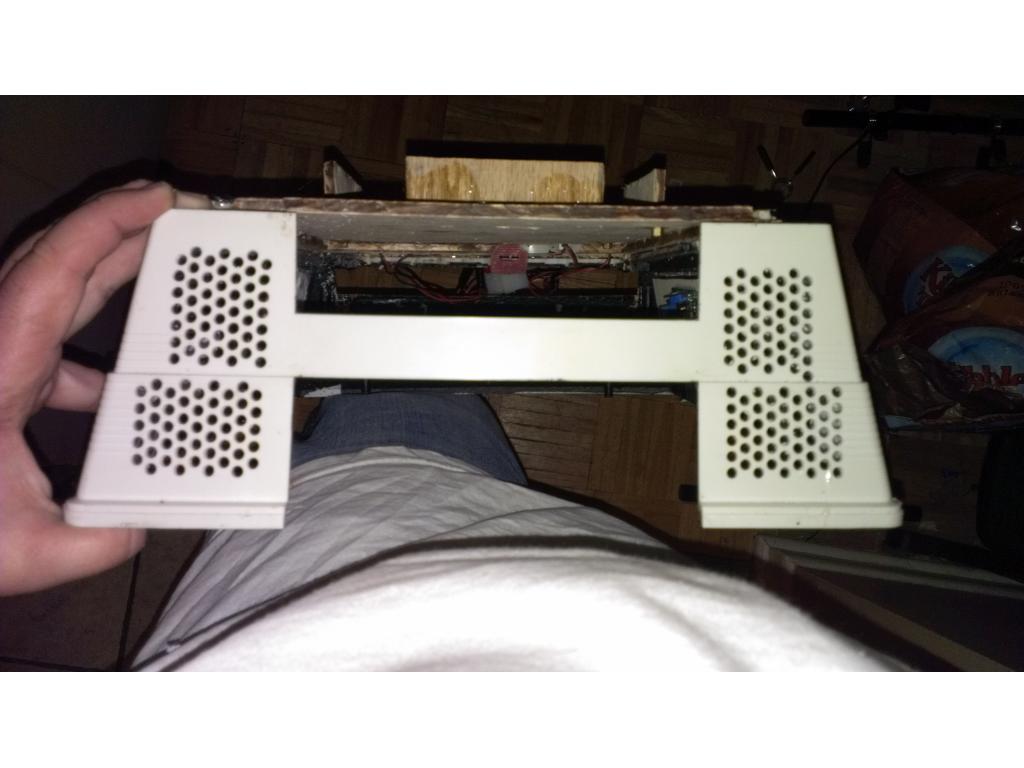
Updating my progress thread , adding pics of the sound.deadening progress.
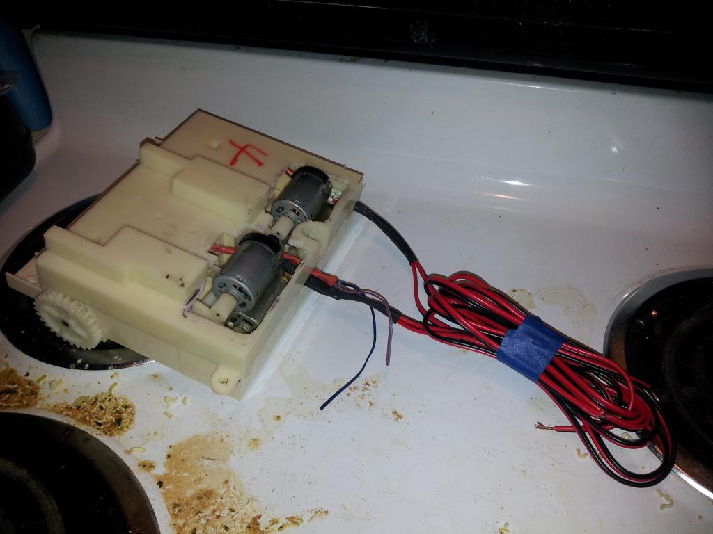
Im thinking of adding a second omnibot gearbox and.wheels in place of the dummy wheels that were in the back. This is a backup idea because my bot will weight 15 to 20 pounds over stock fully loaded. Anyone think lining up a second gearbox to drive only the rear wheels? I have a gearbox and extra stock wheels. Motherboard , CPU , more batteries , fan controller , CPU heatsink , 6 micro 40mm ultra quiet low current draw fans are on the way. So can I use more than one ultrasound sensor on a bot for mapping? For example on on head and one near floor. That way he doesn't run into the edge of the workbench , person or table.
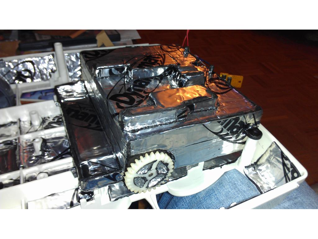
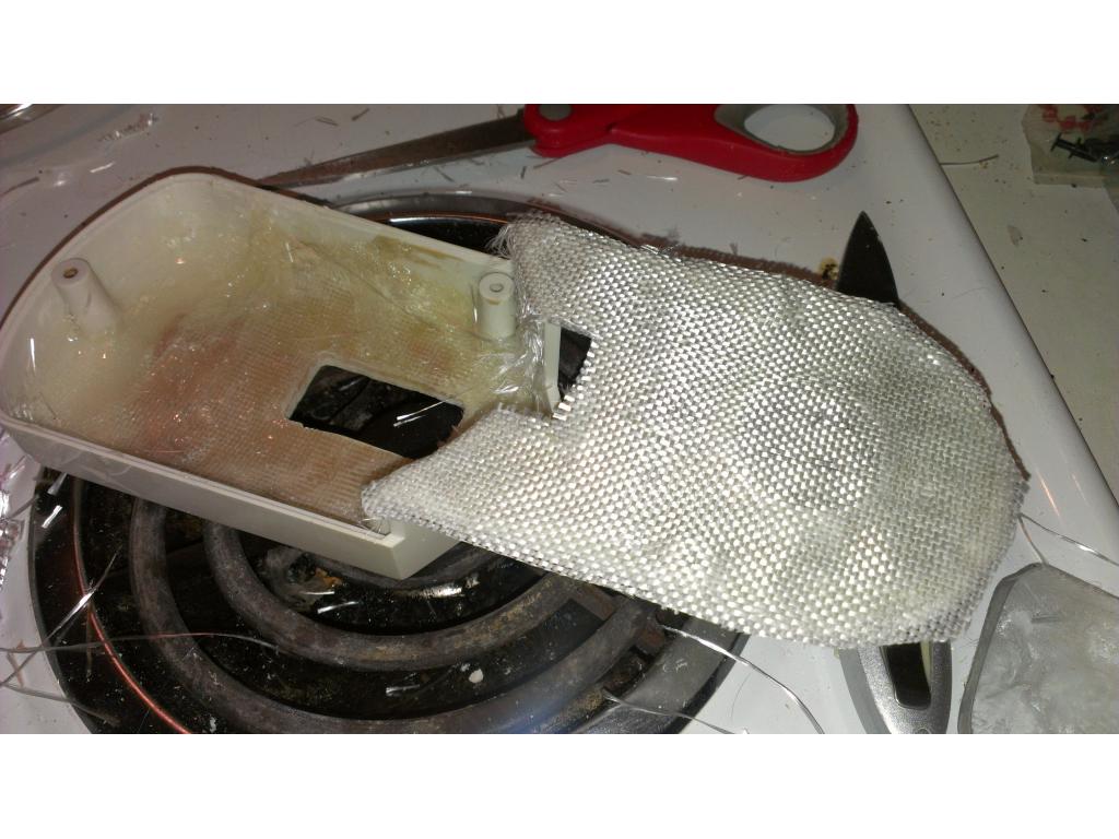
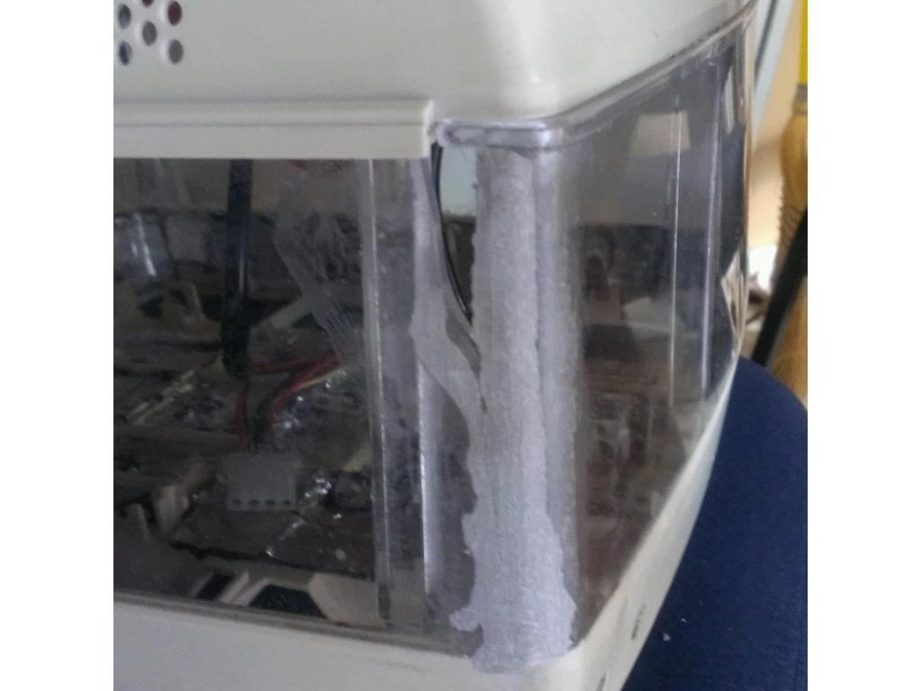
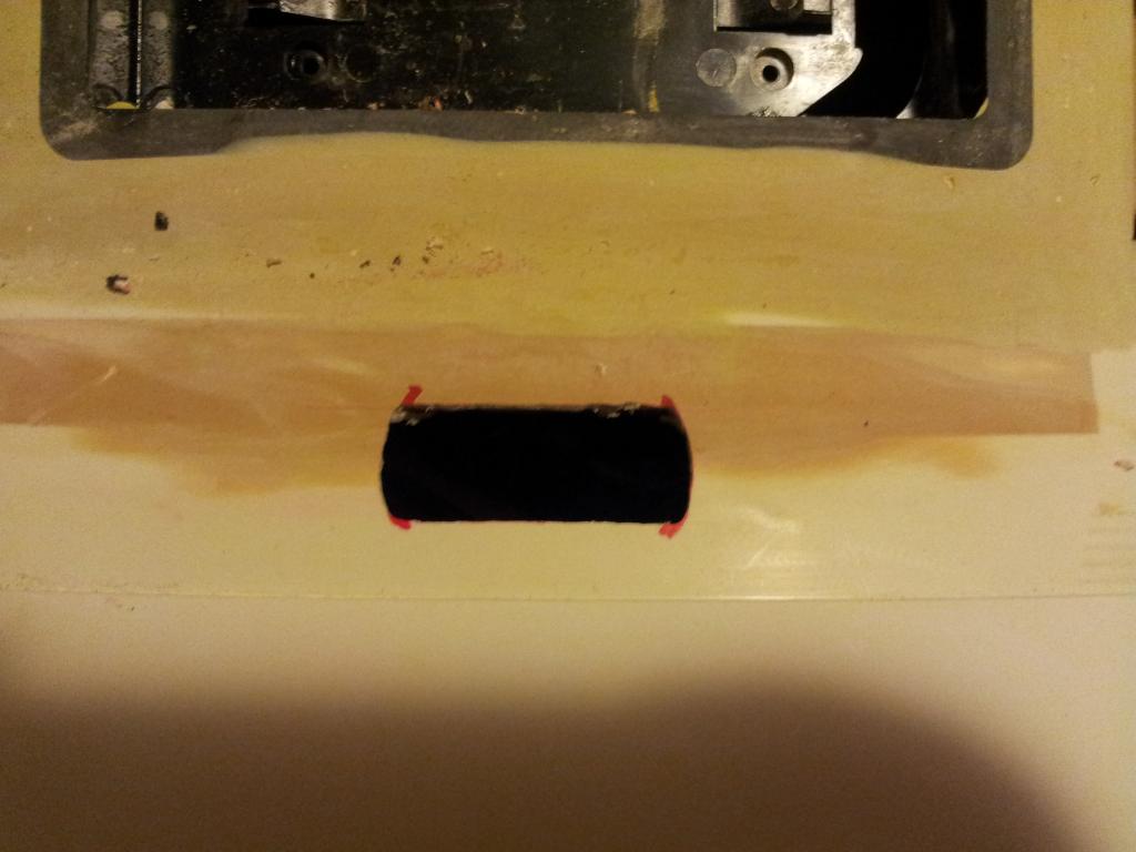
@jstarne1 did you wrap the enire motor? I think I may want to get some of that. But then again, now I am thinking about scrapping my omnibot build and just working on my big bot. After seeing RCRichie and his daughter's scratch-built - I have the bug. lol
If you do scrap it let me know I would love to get some parts from you , like drive train maybe wheels
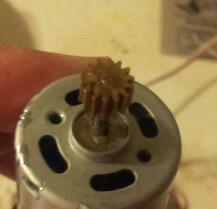
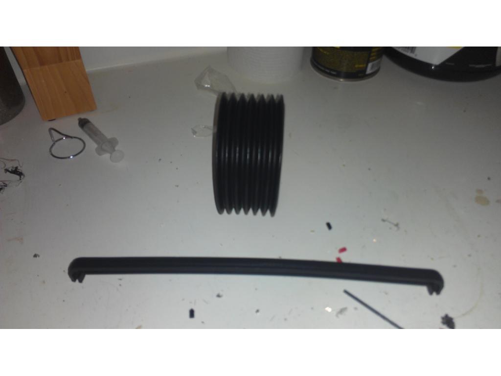
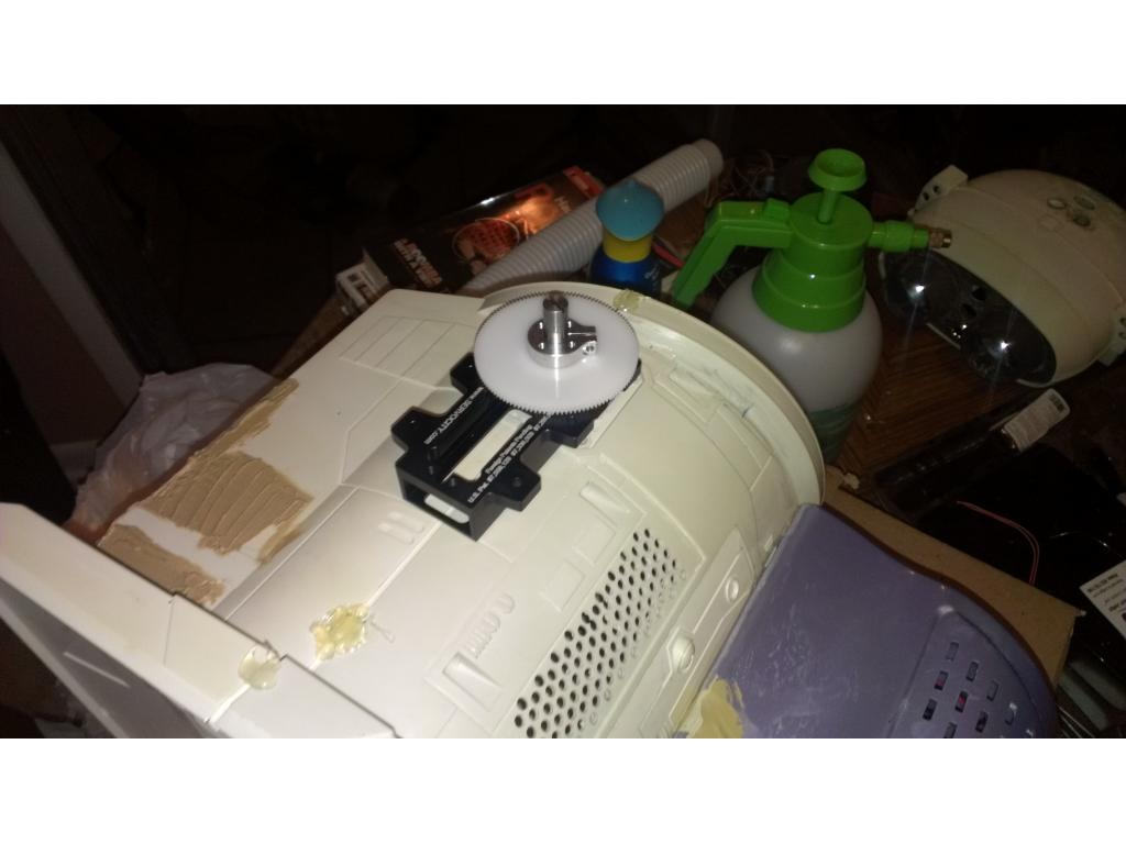
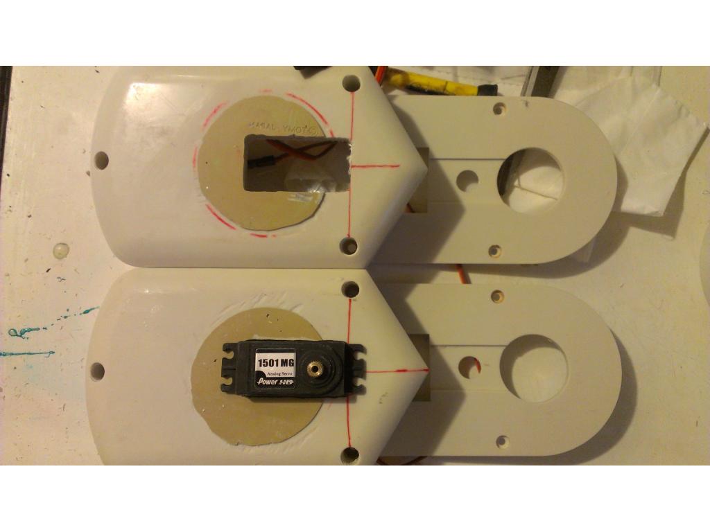
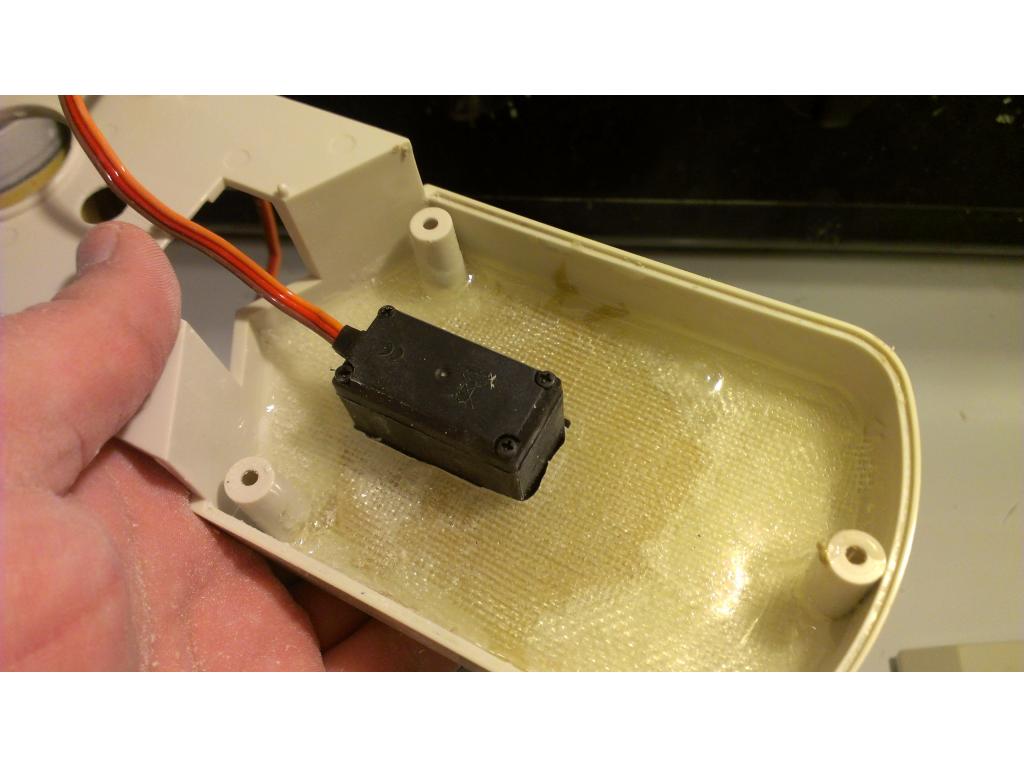
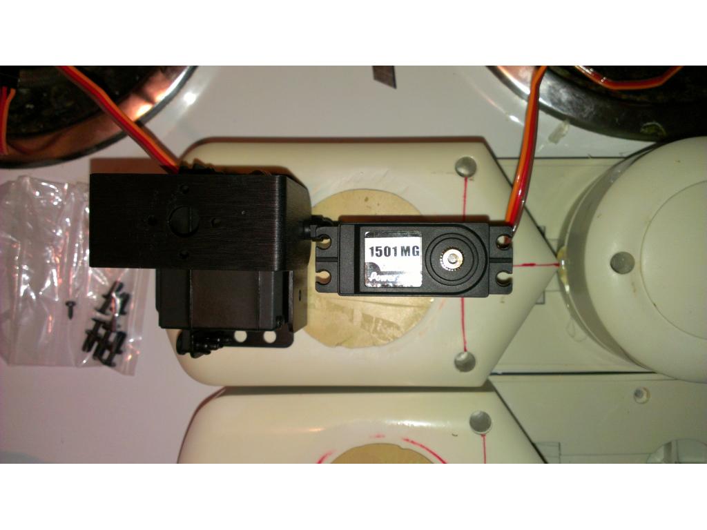
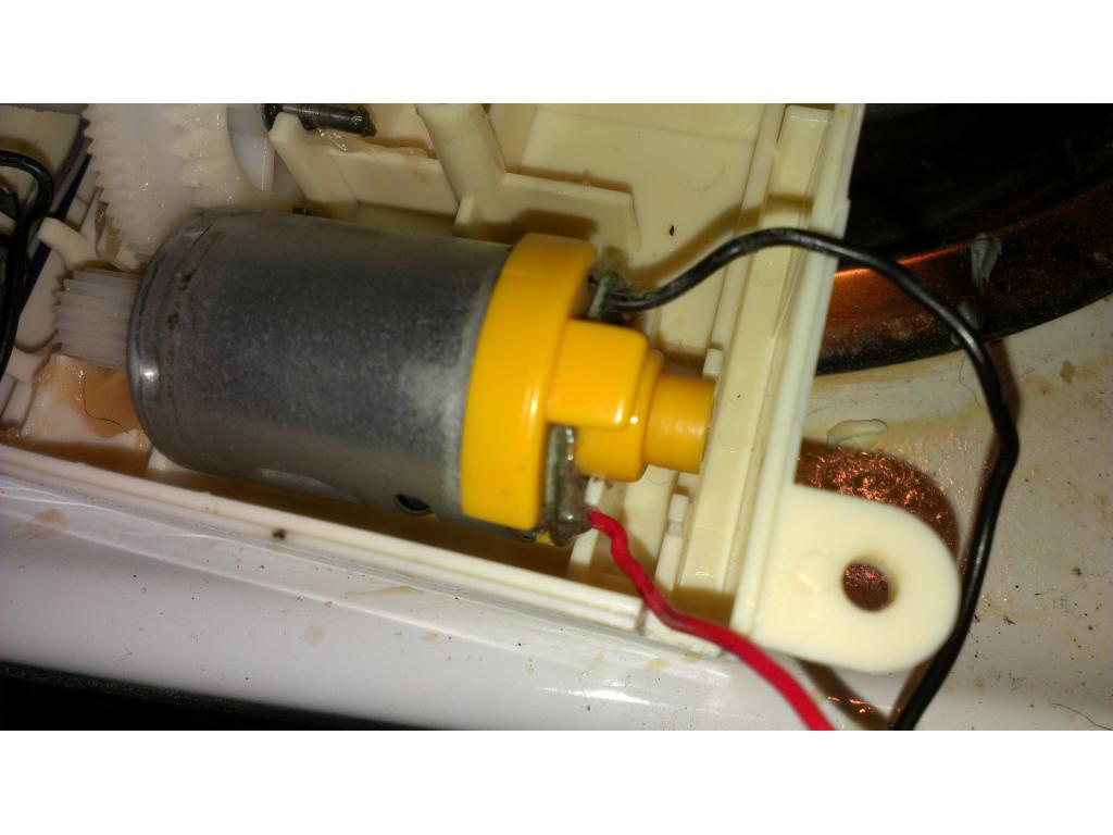
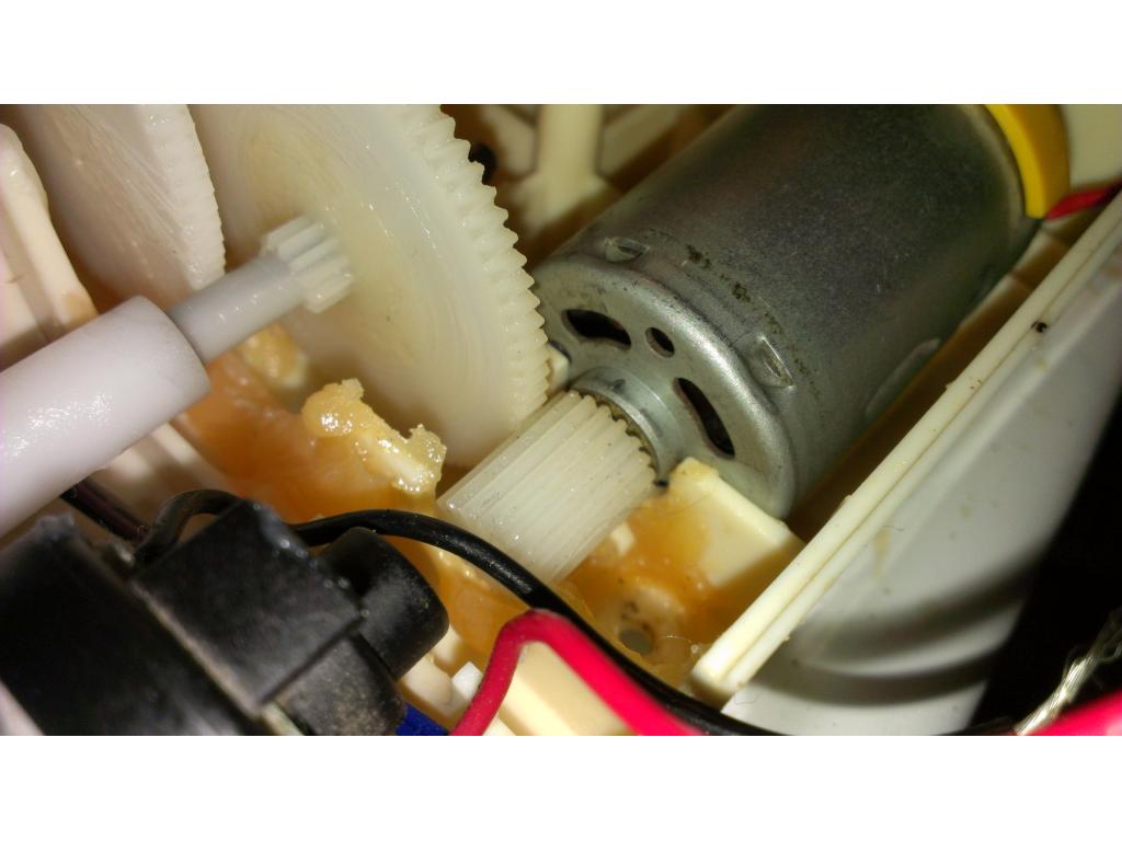
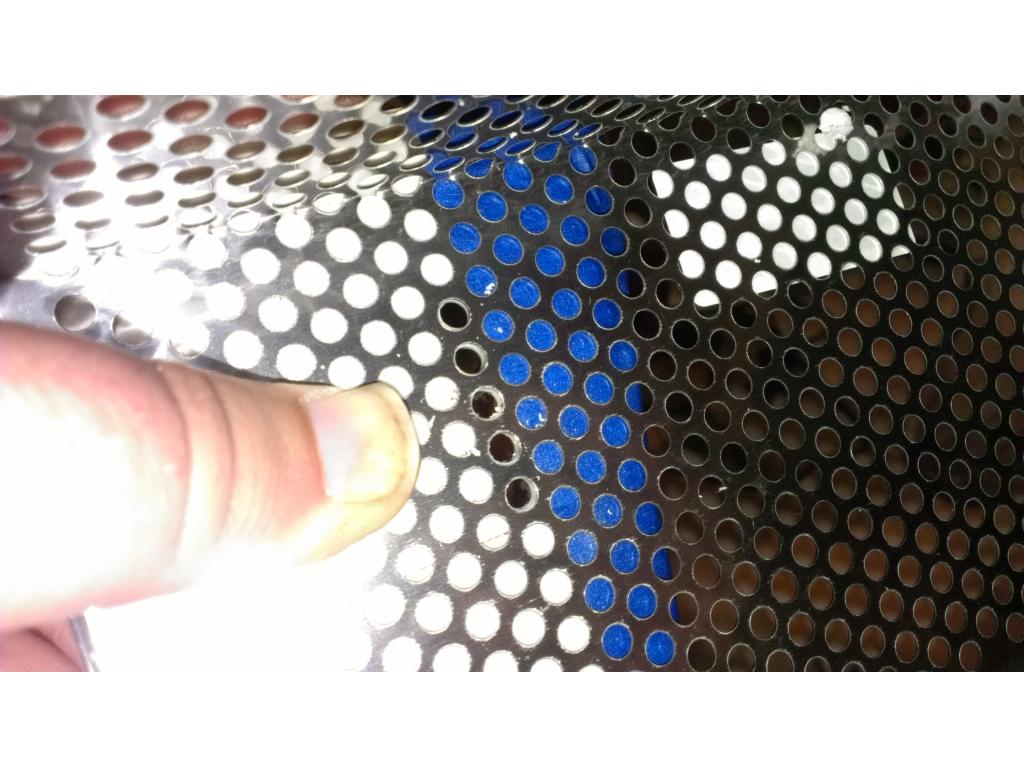
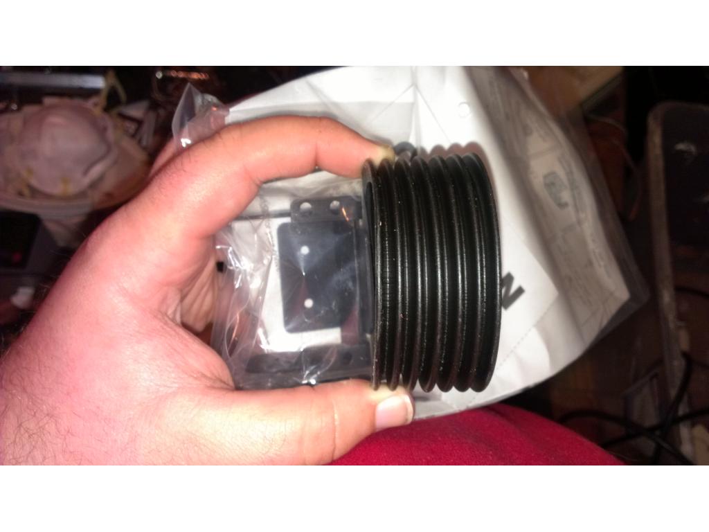
I only wrapped the center of the motor , and outside surfaces of the case. The rubber grommets are mounts that hold the motor in place. Can't wait to get this dude moving around!
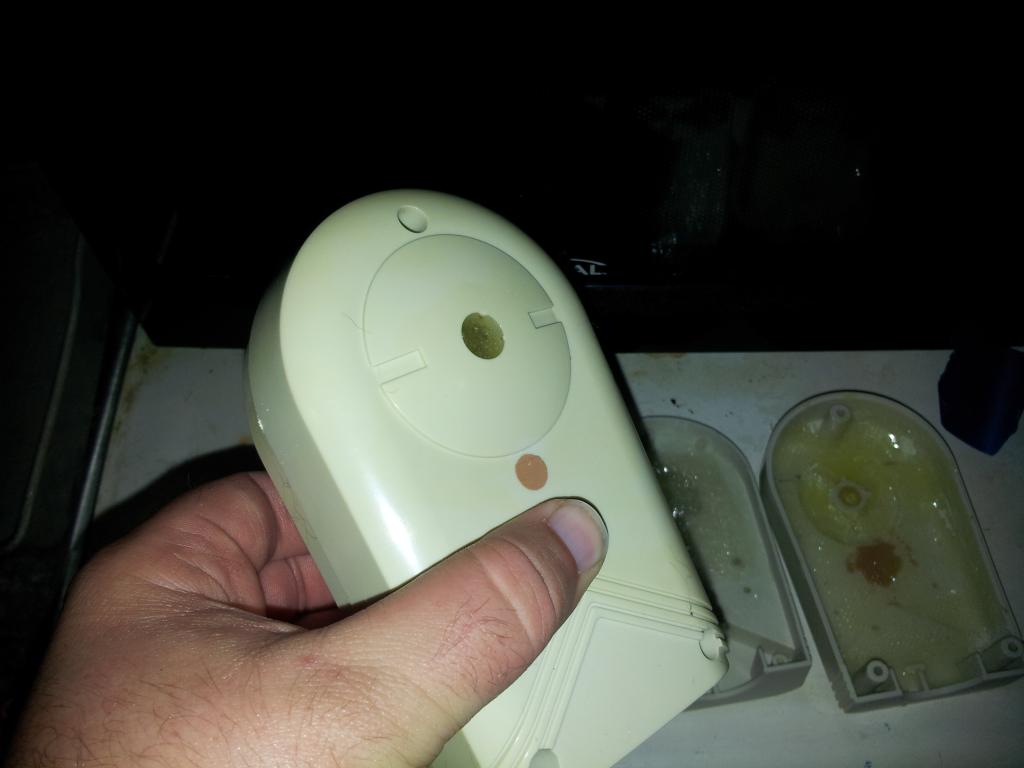
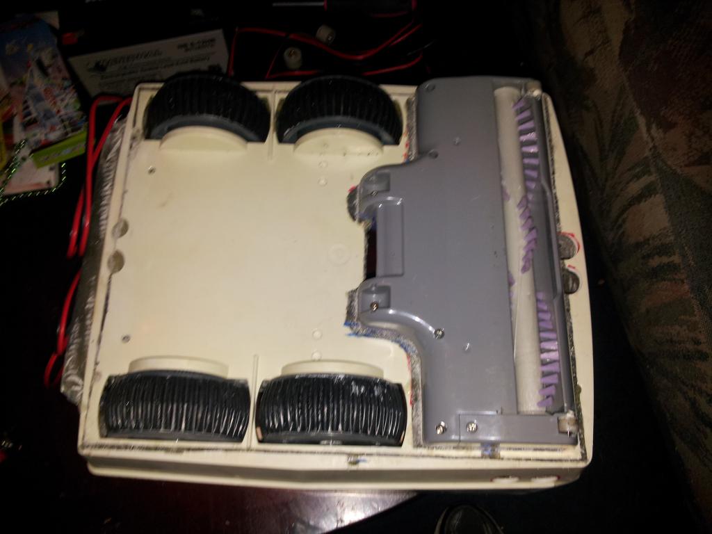
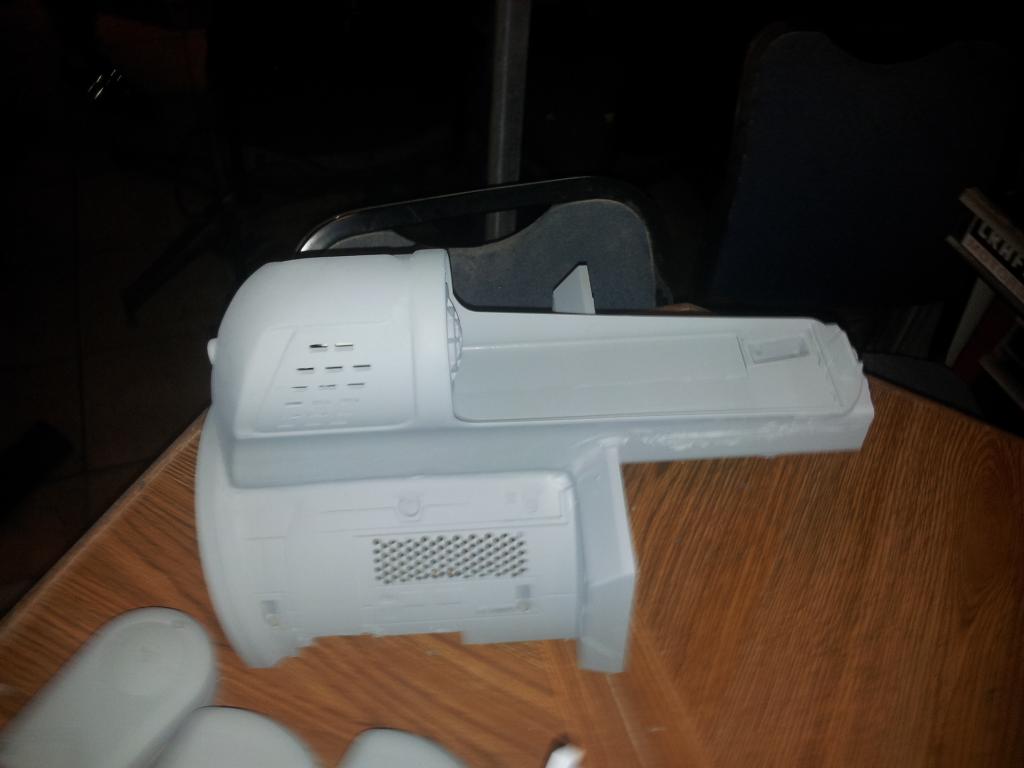
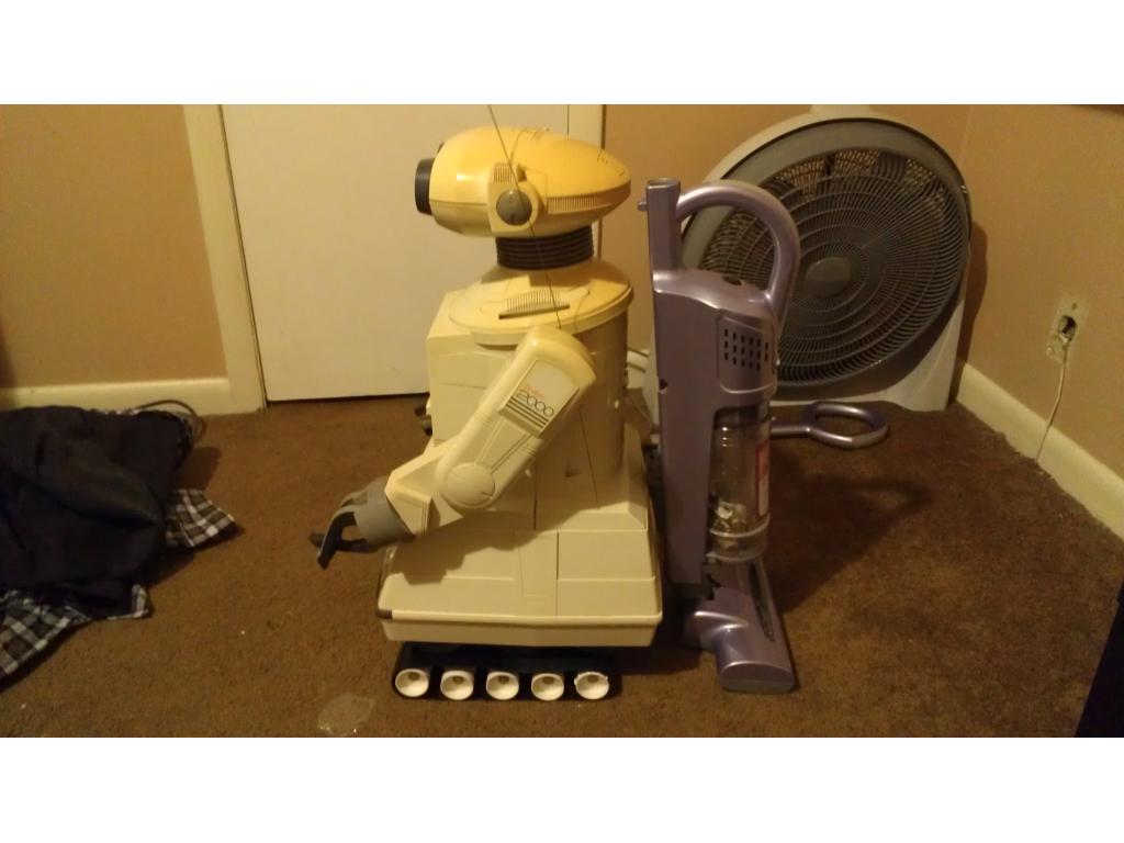
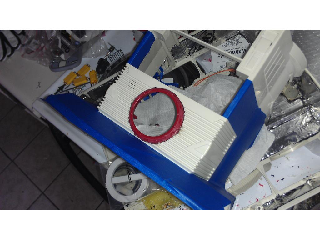
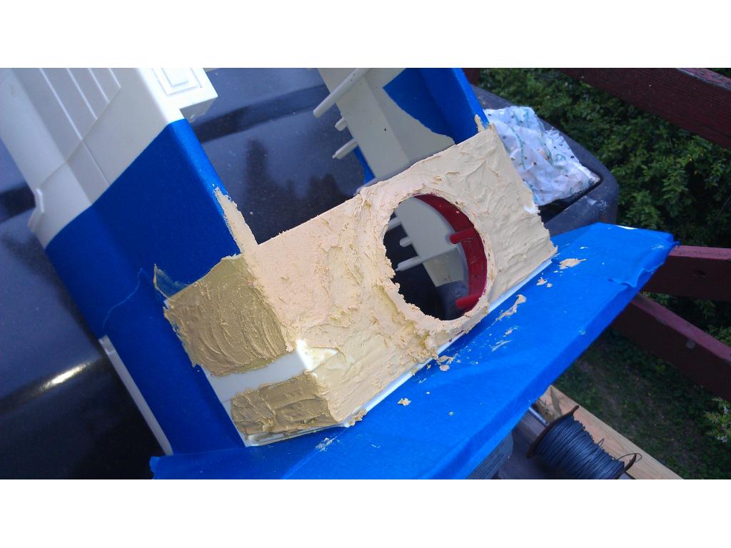
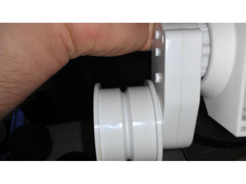
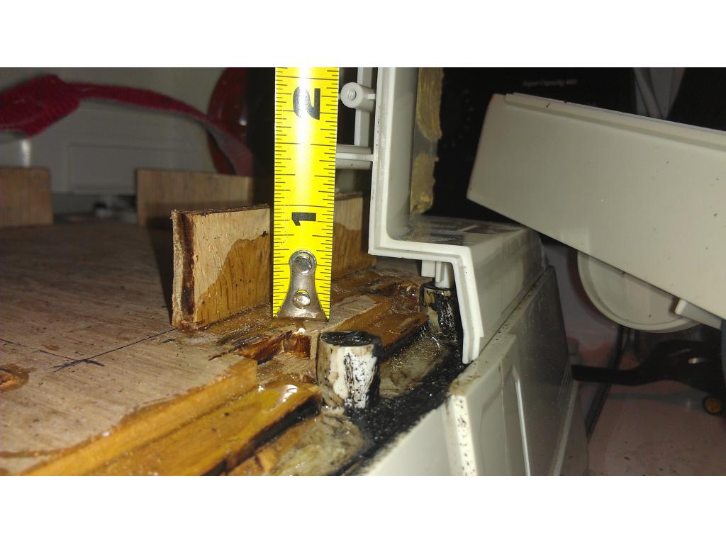
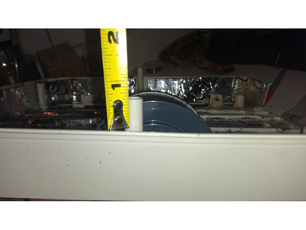
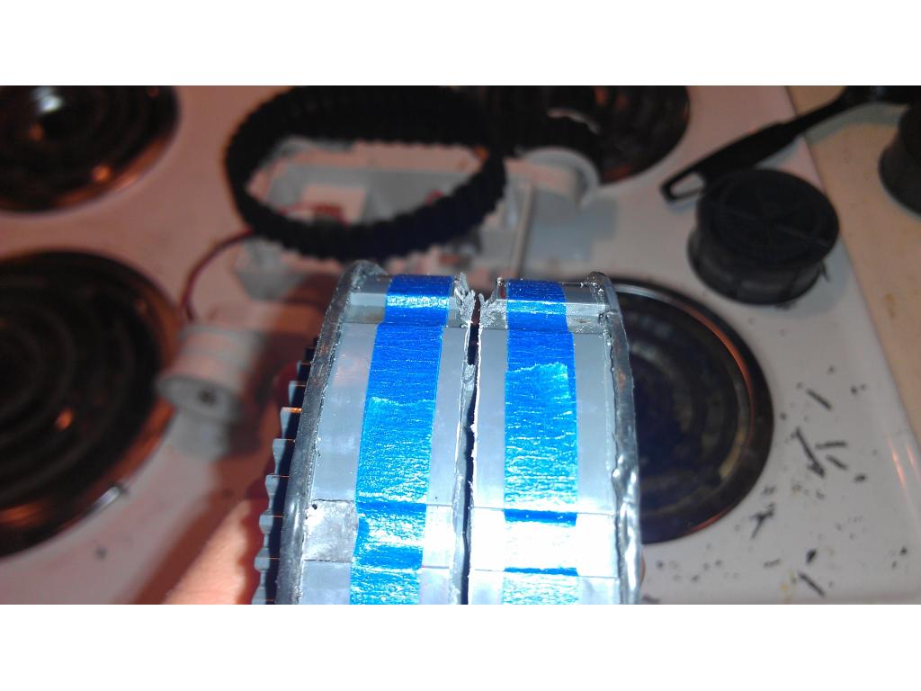
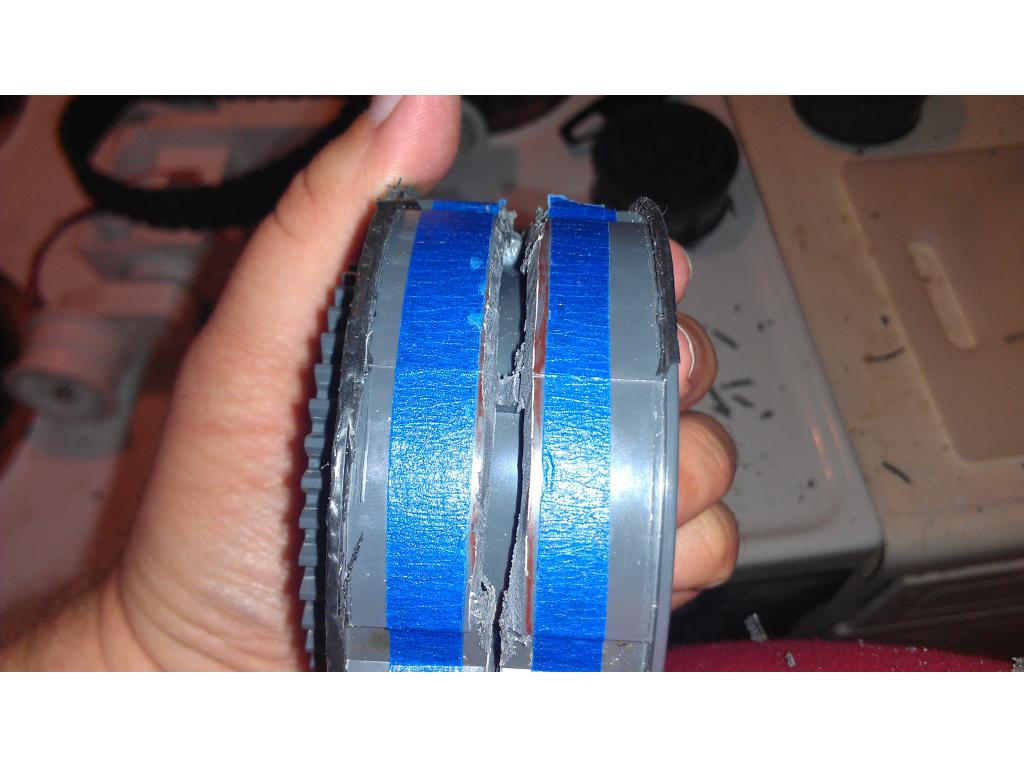
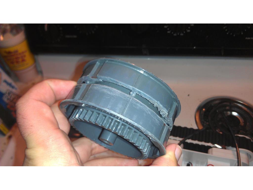
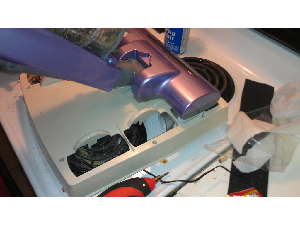
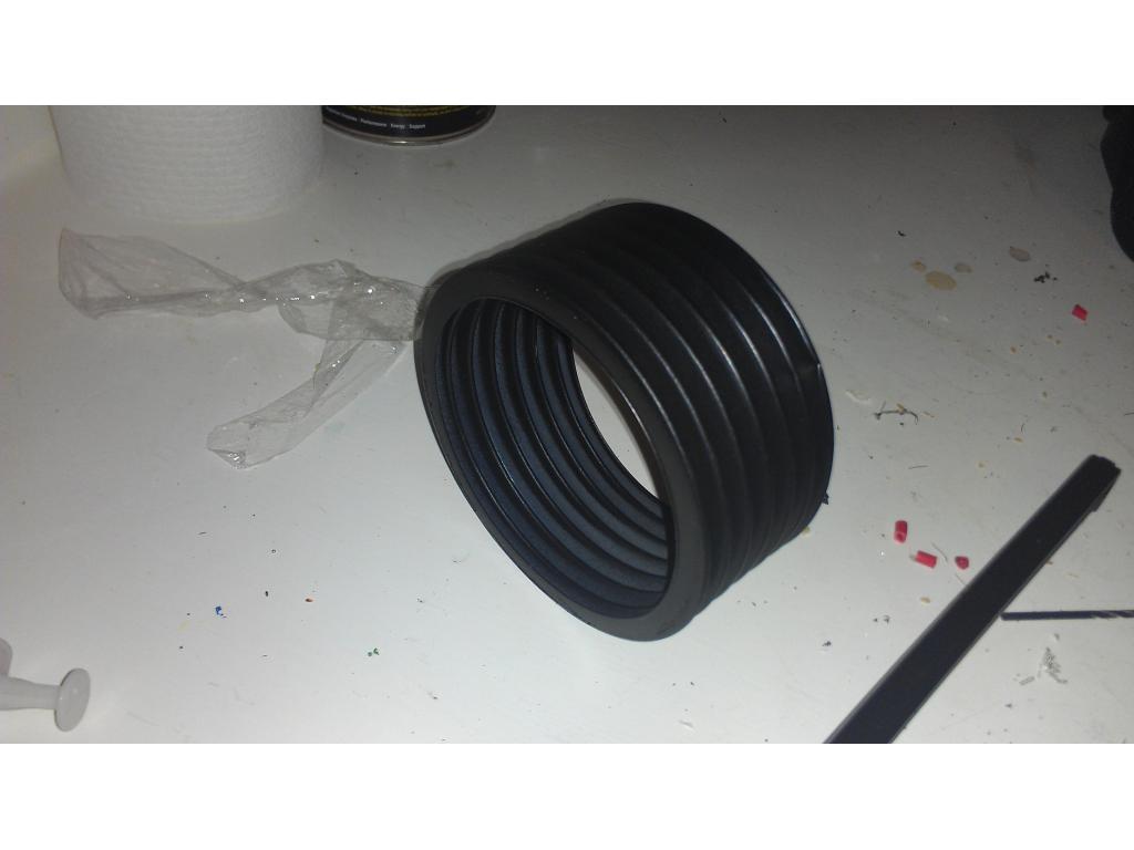
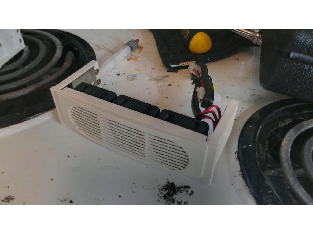
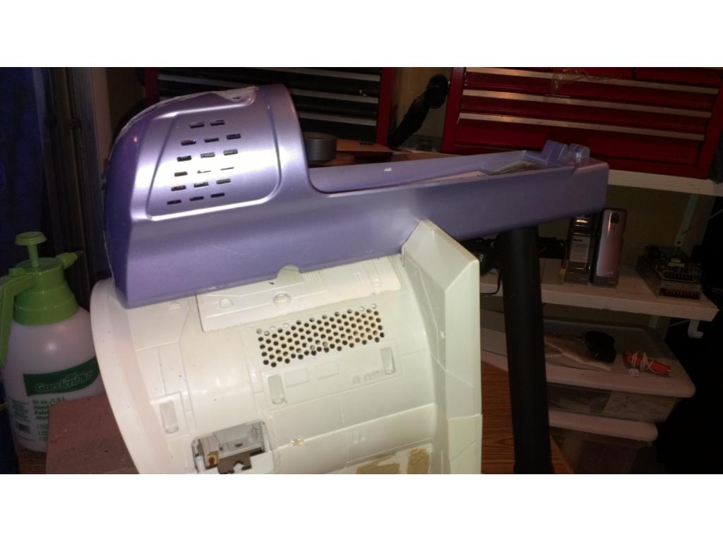
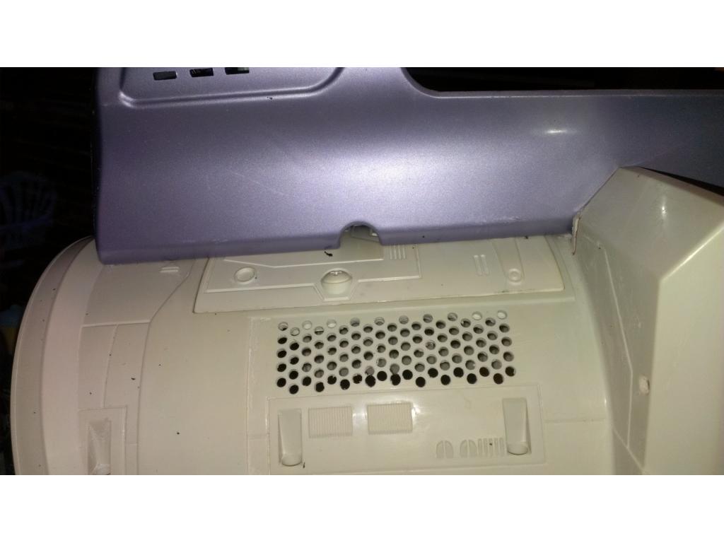
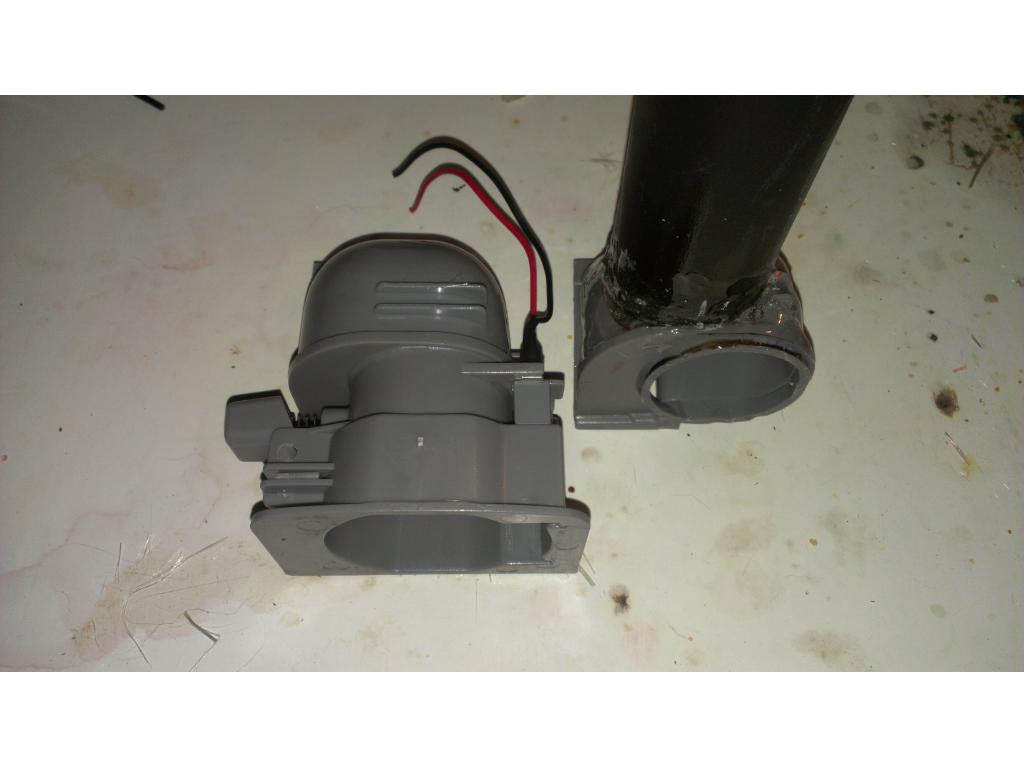
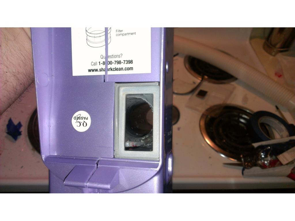
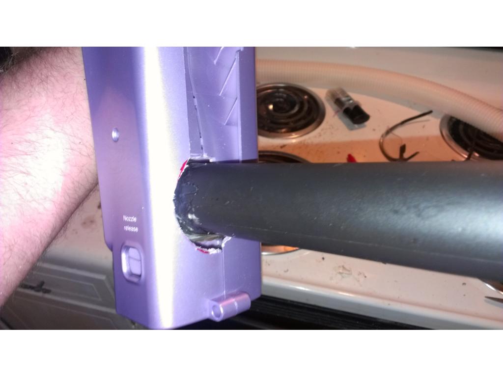
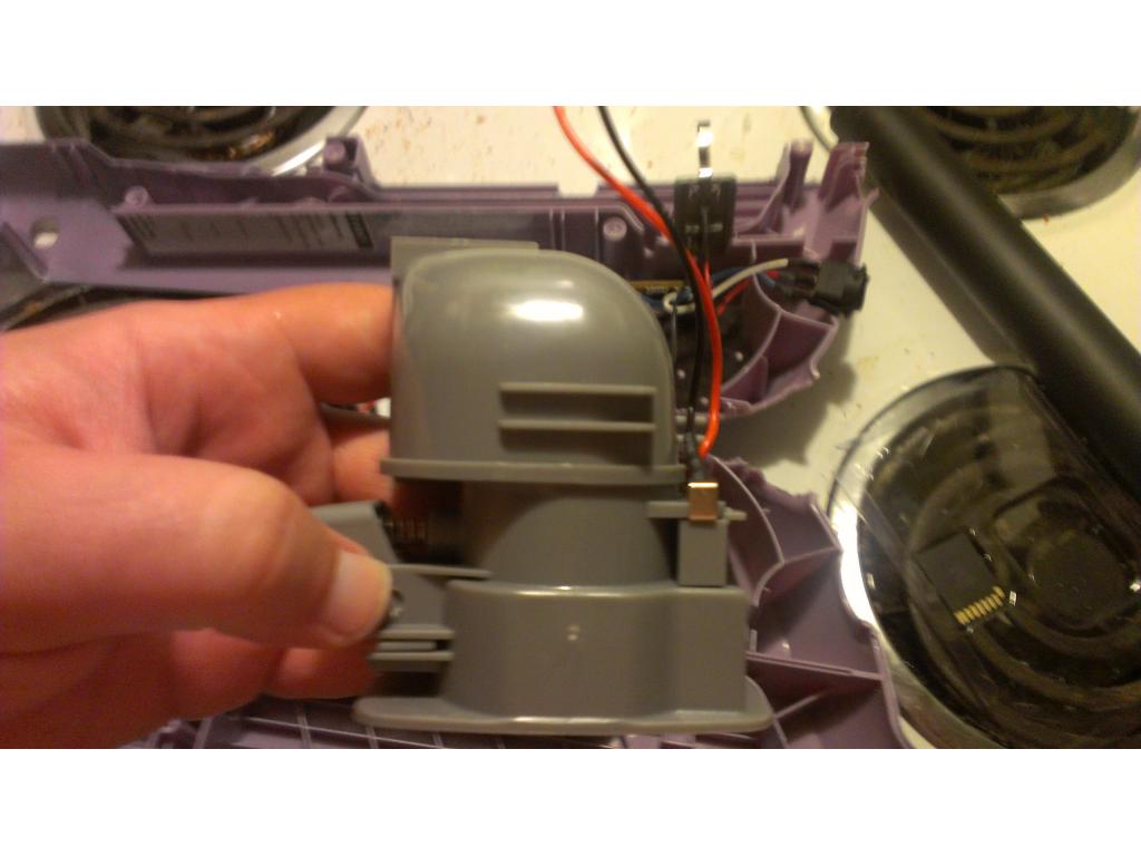
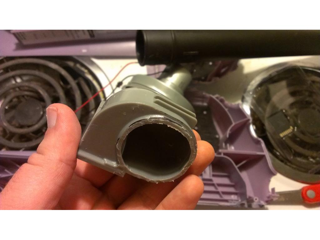
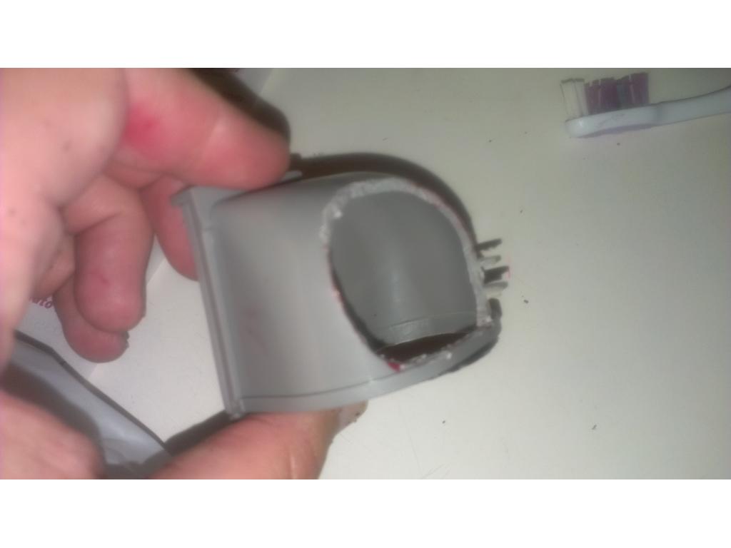
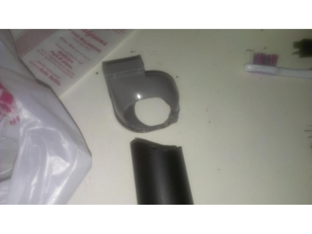
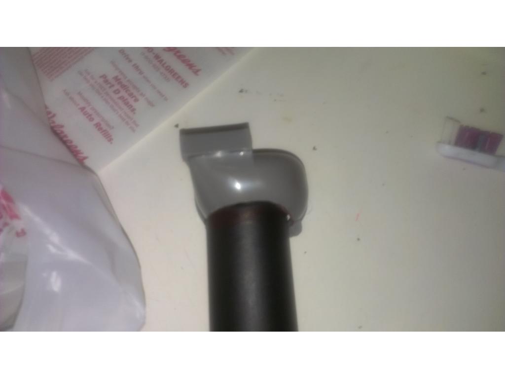
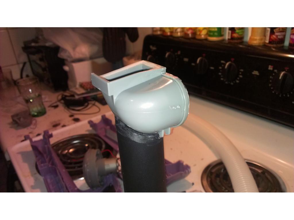
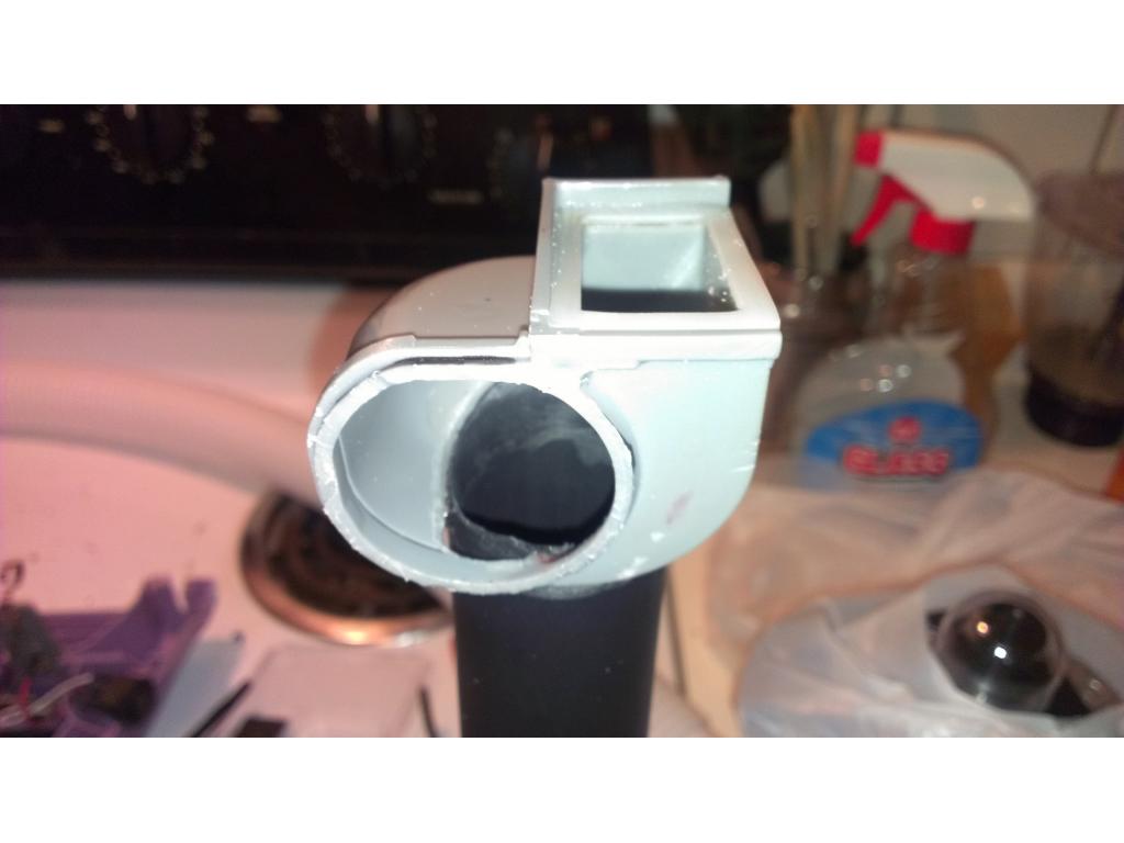
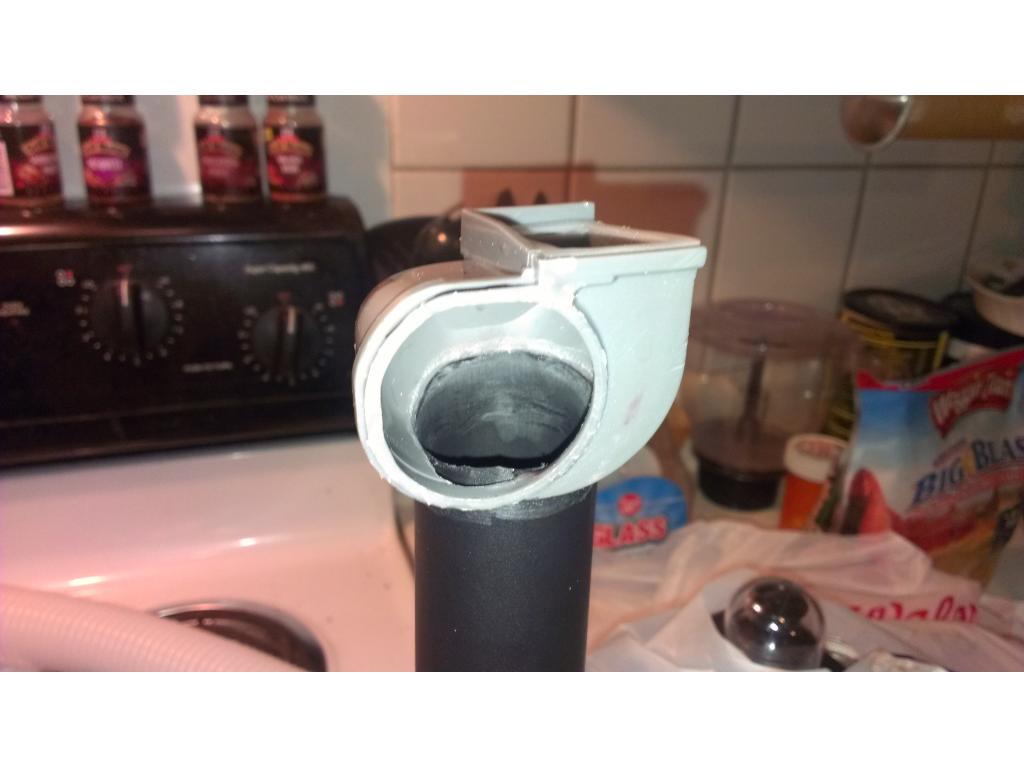
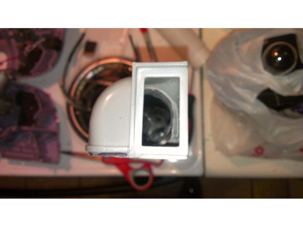
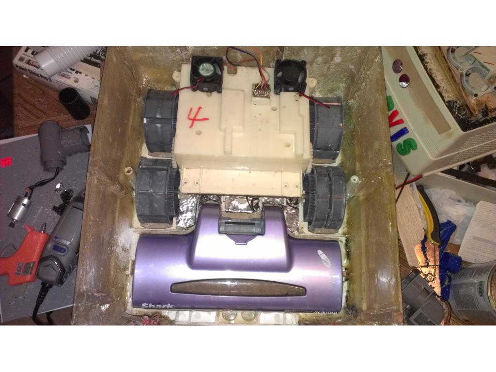
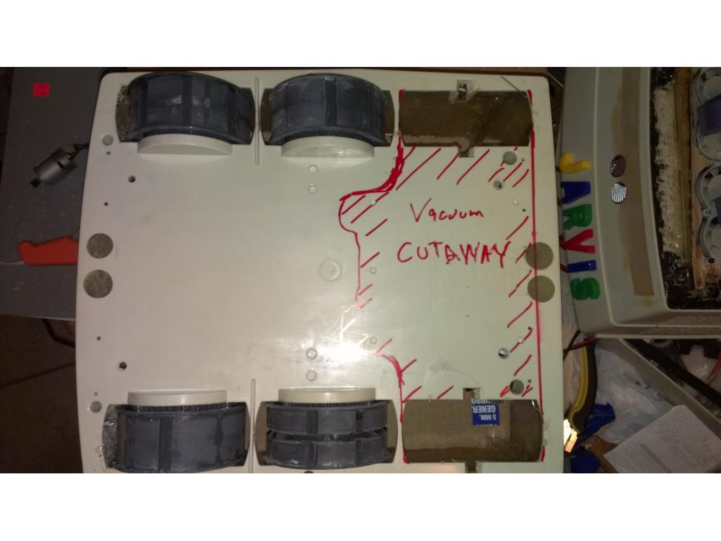
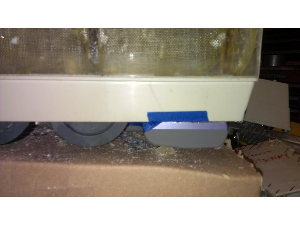
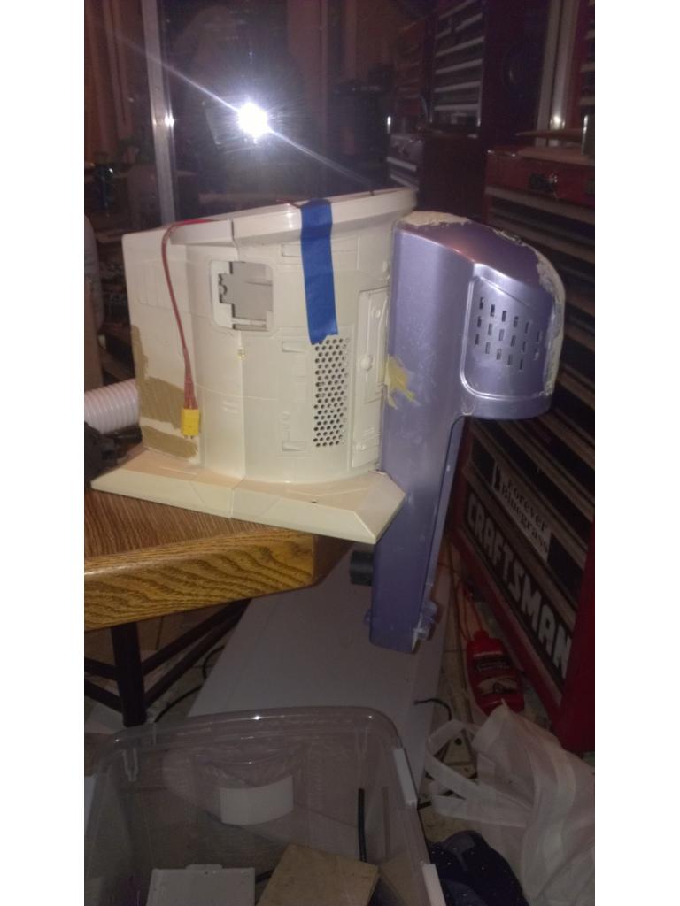
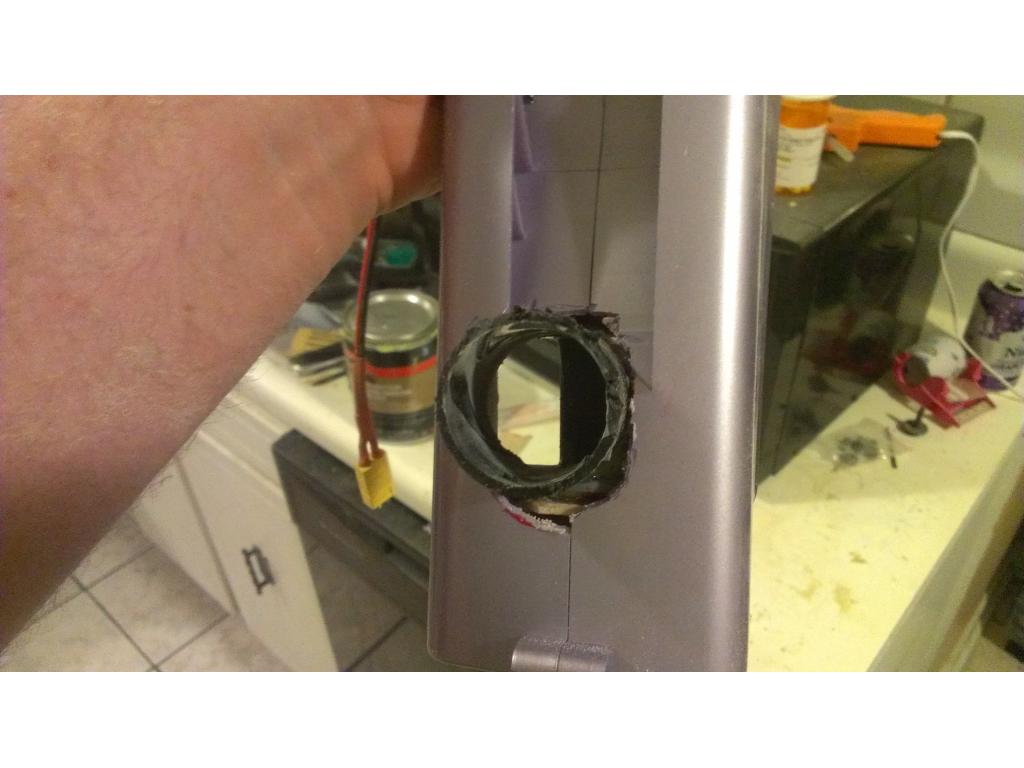
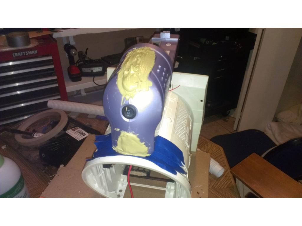
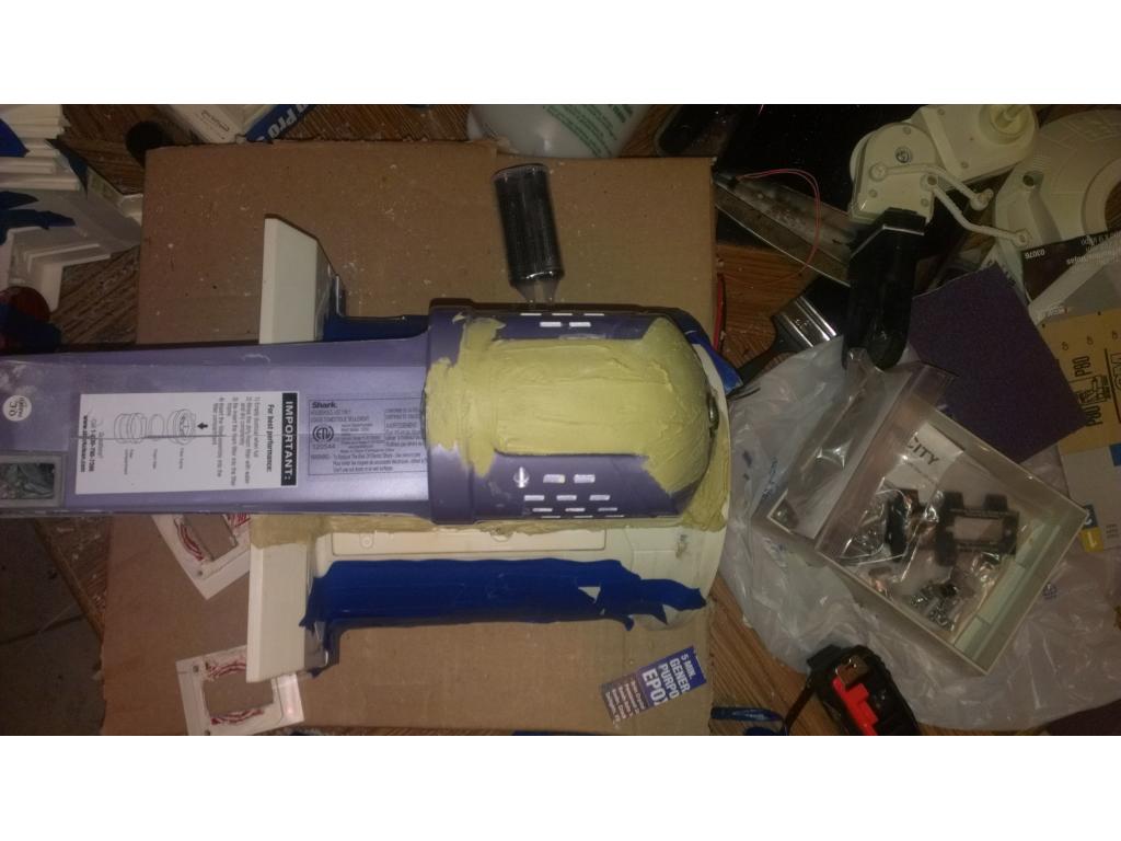
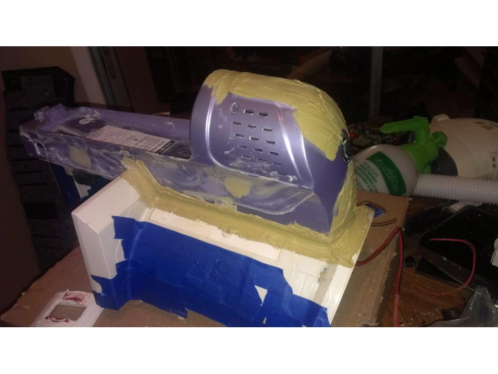
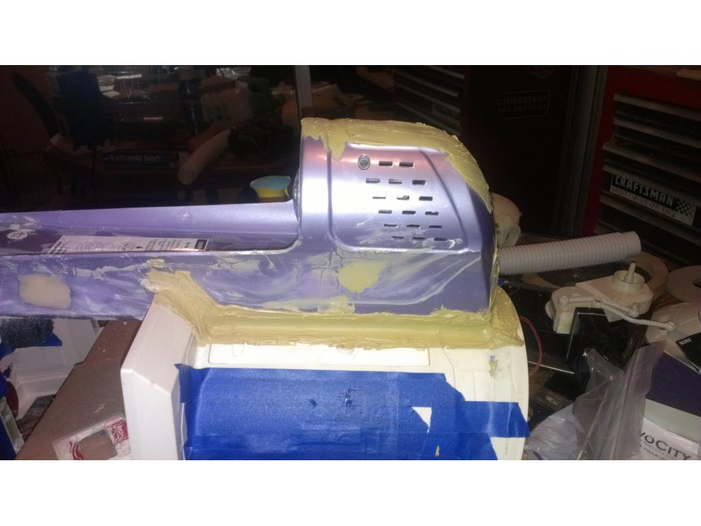
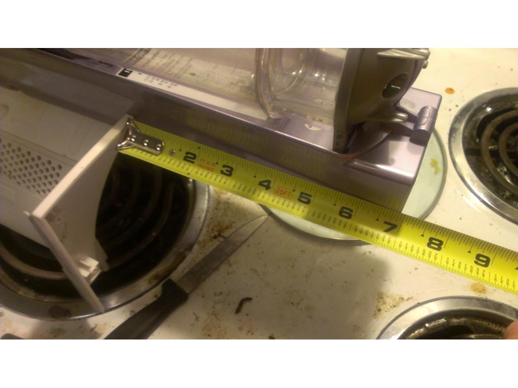
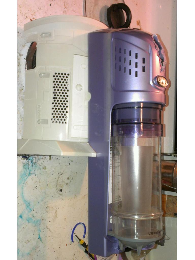
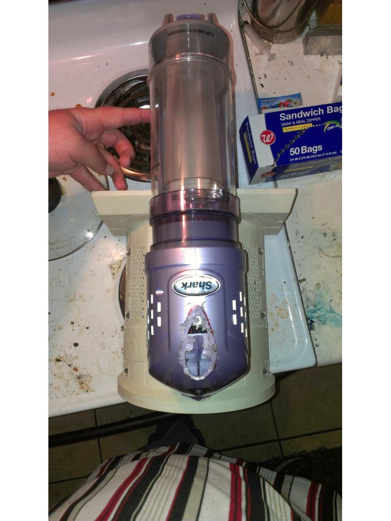
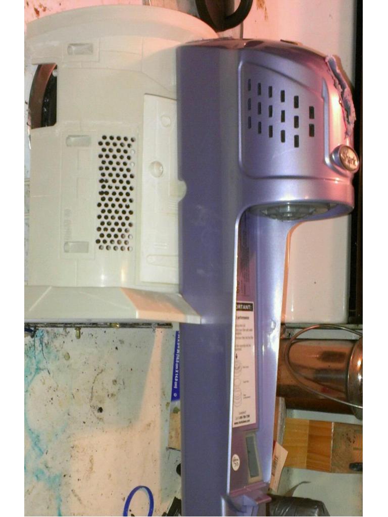
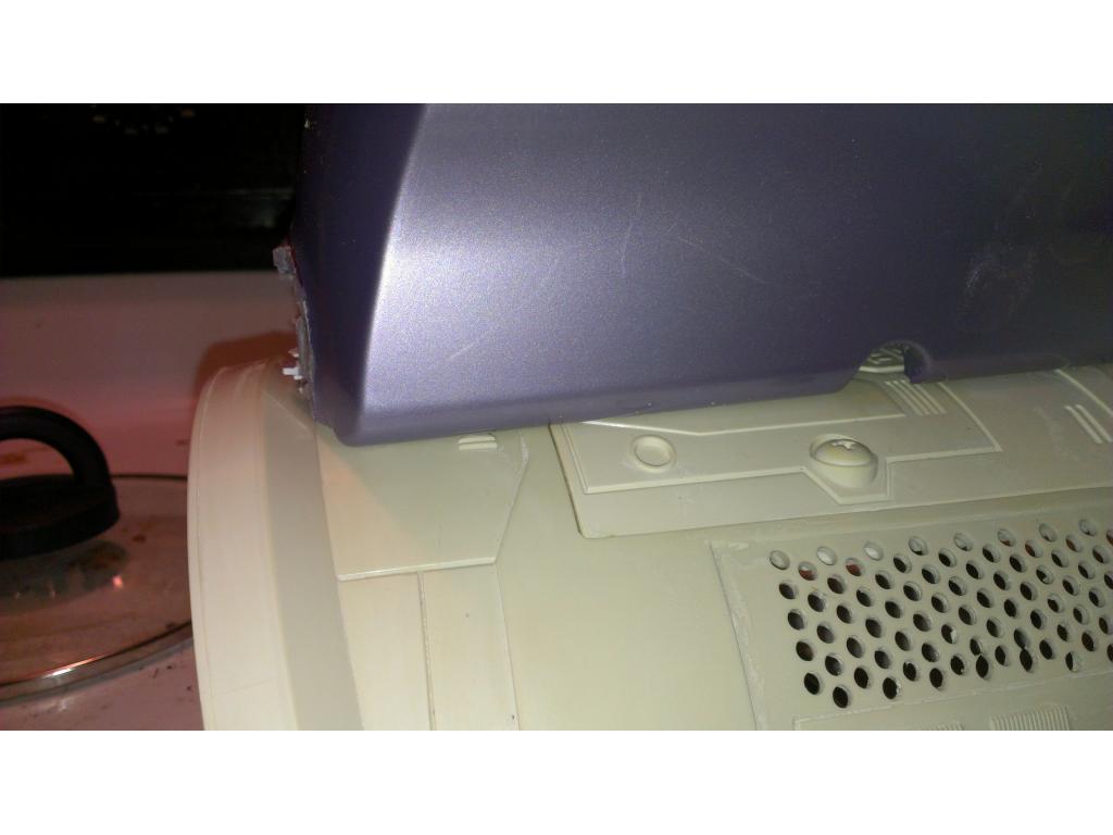
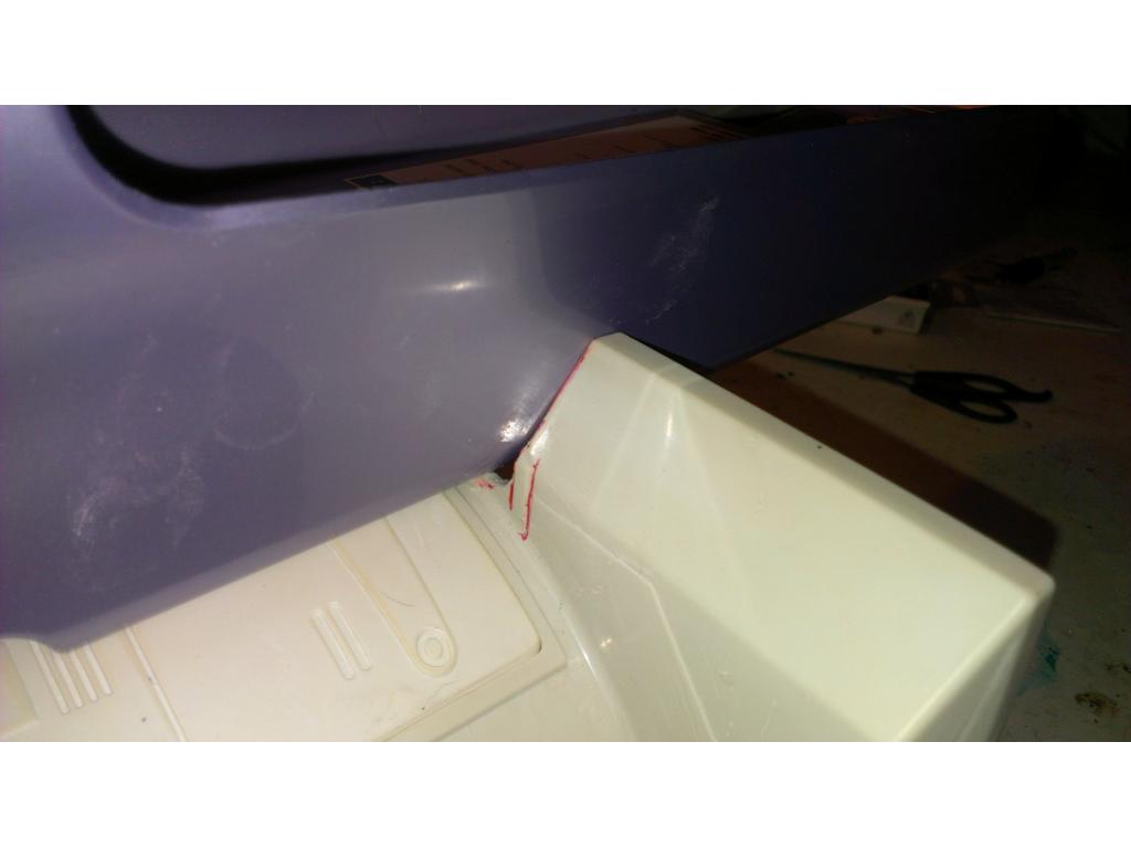
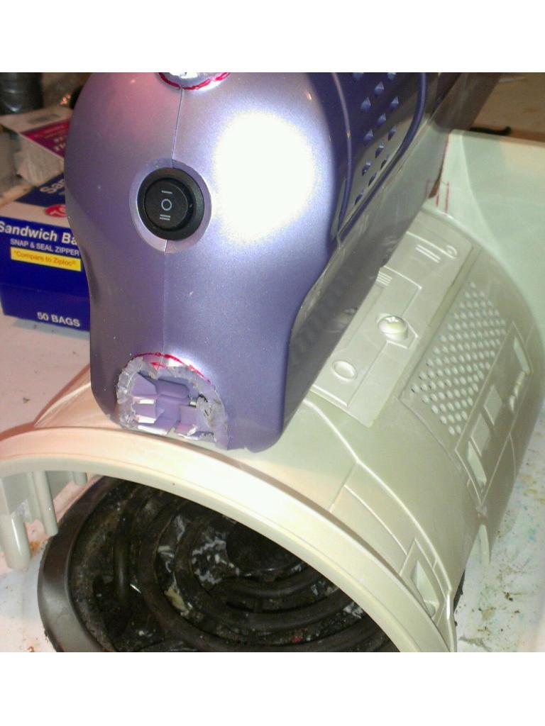
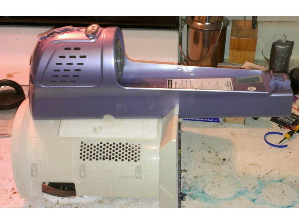
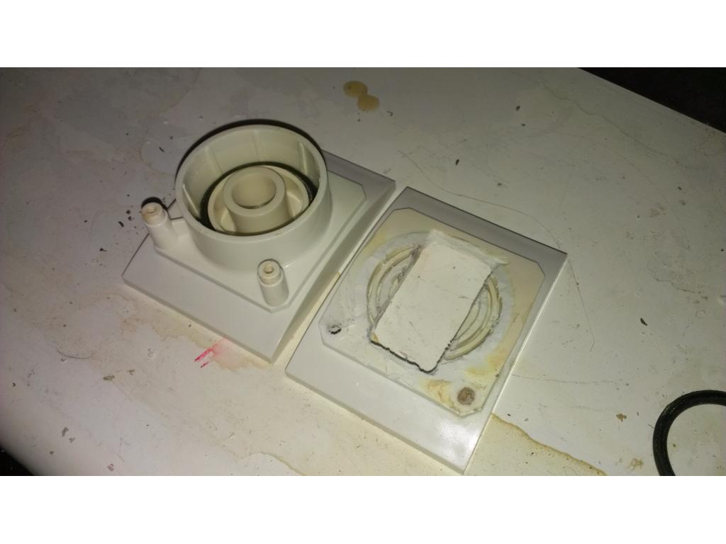
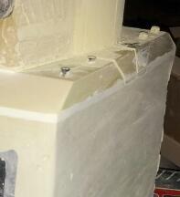
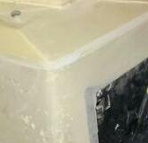
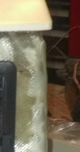
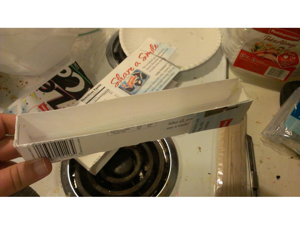
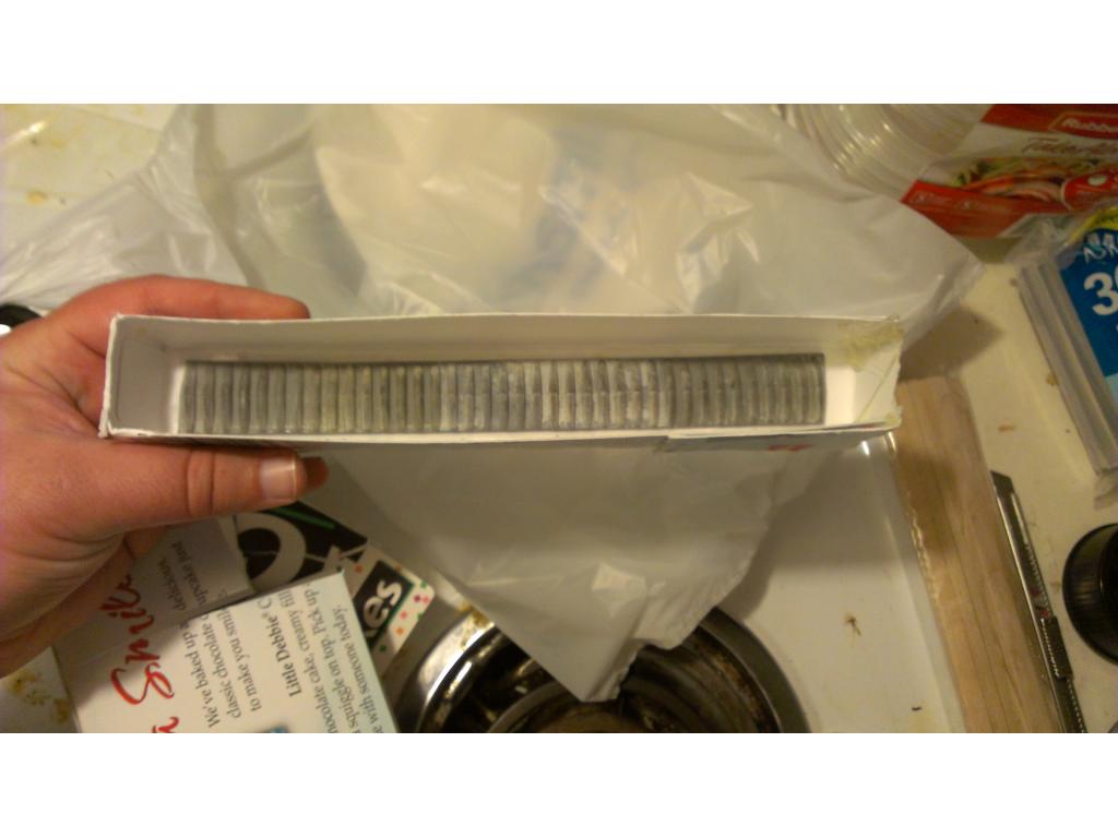
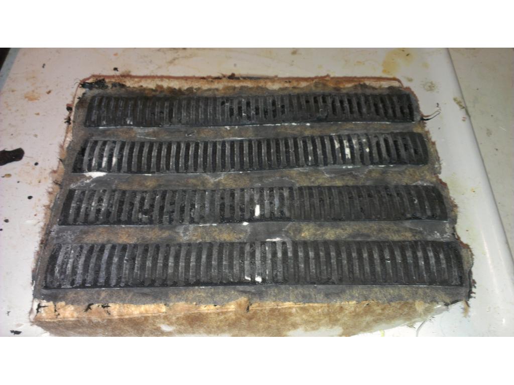
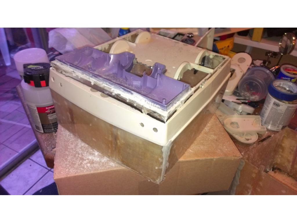
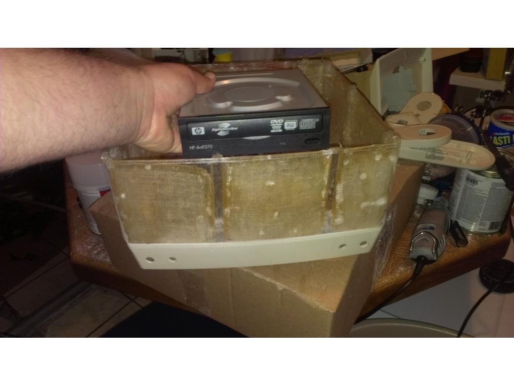
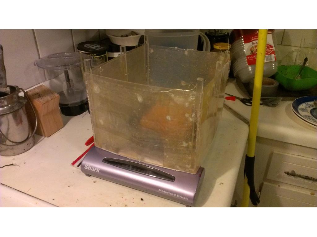
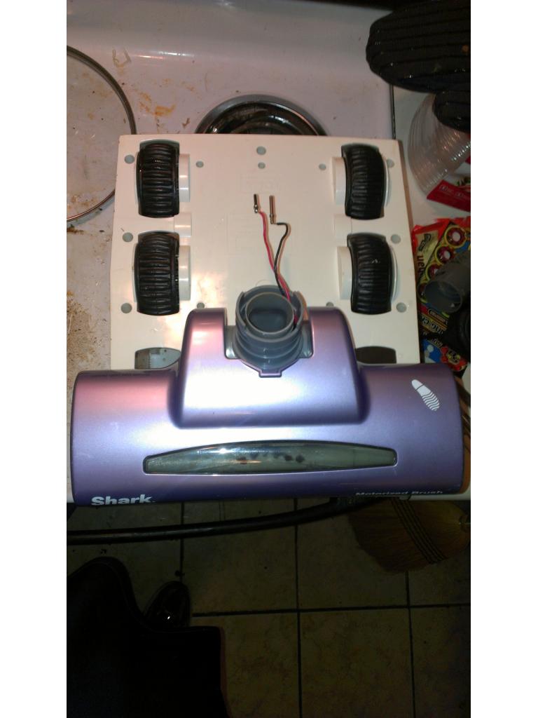
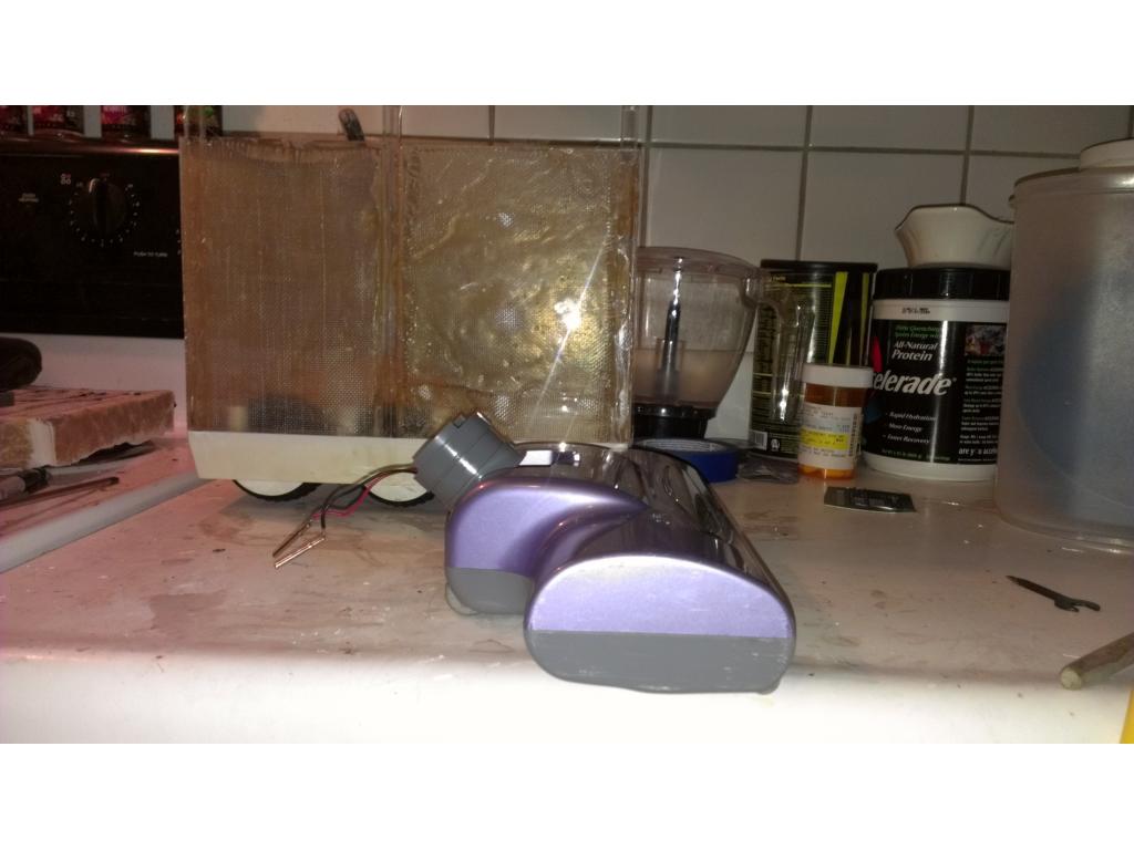
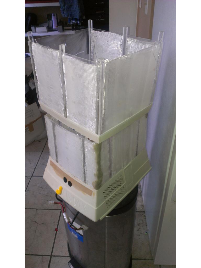
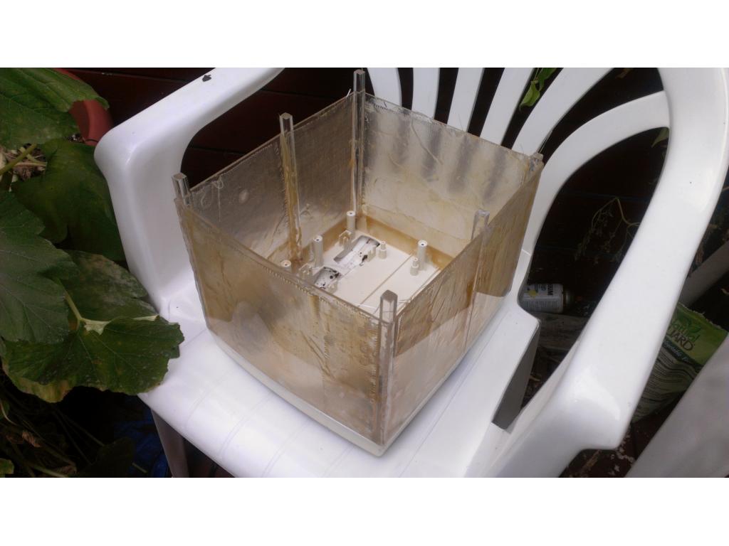
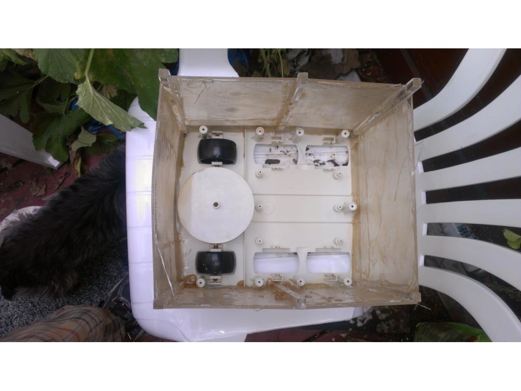
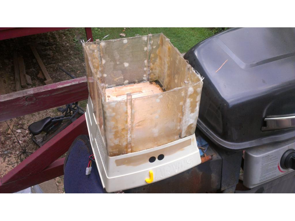
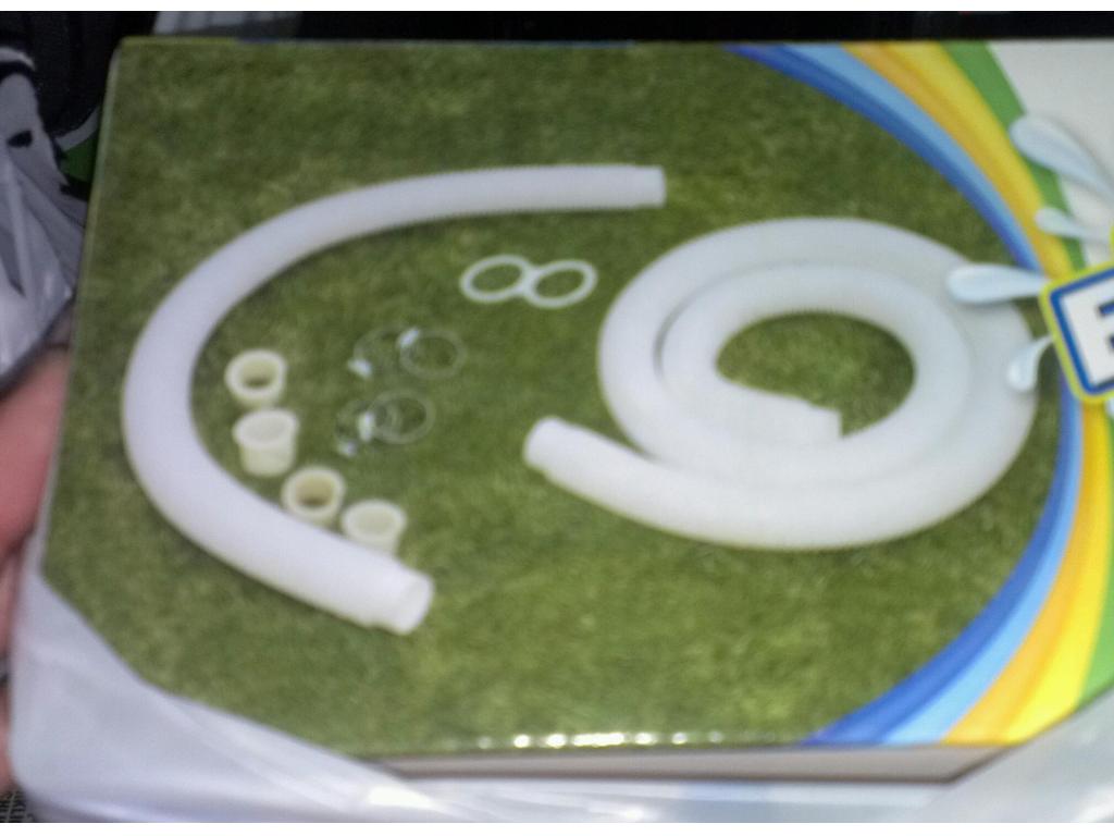
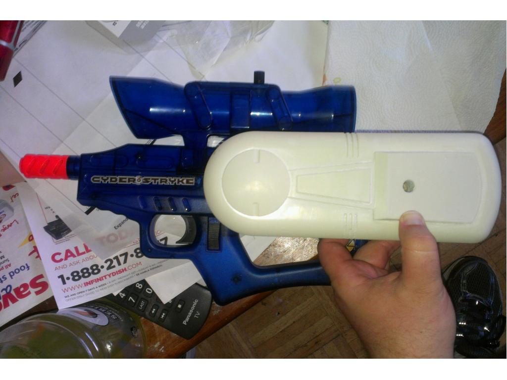
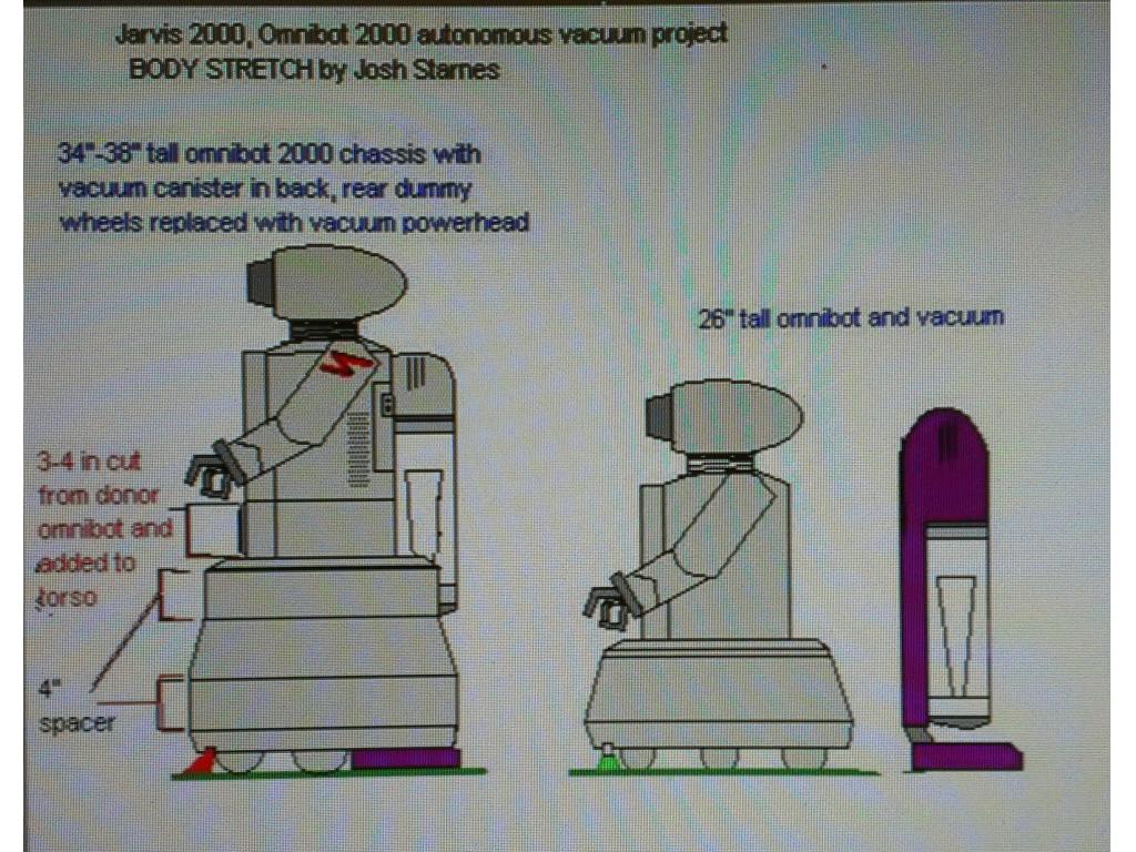
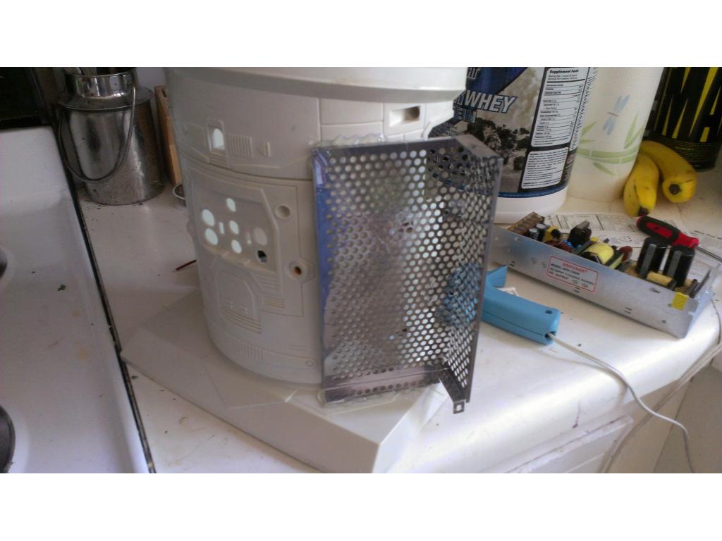
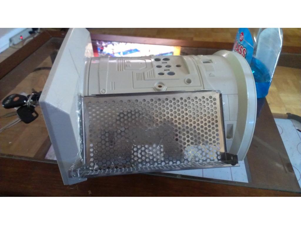
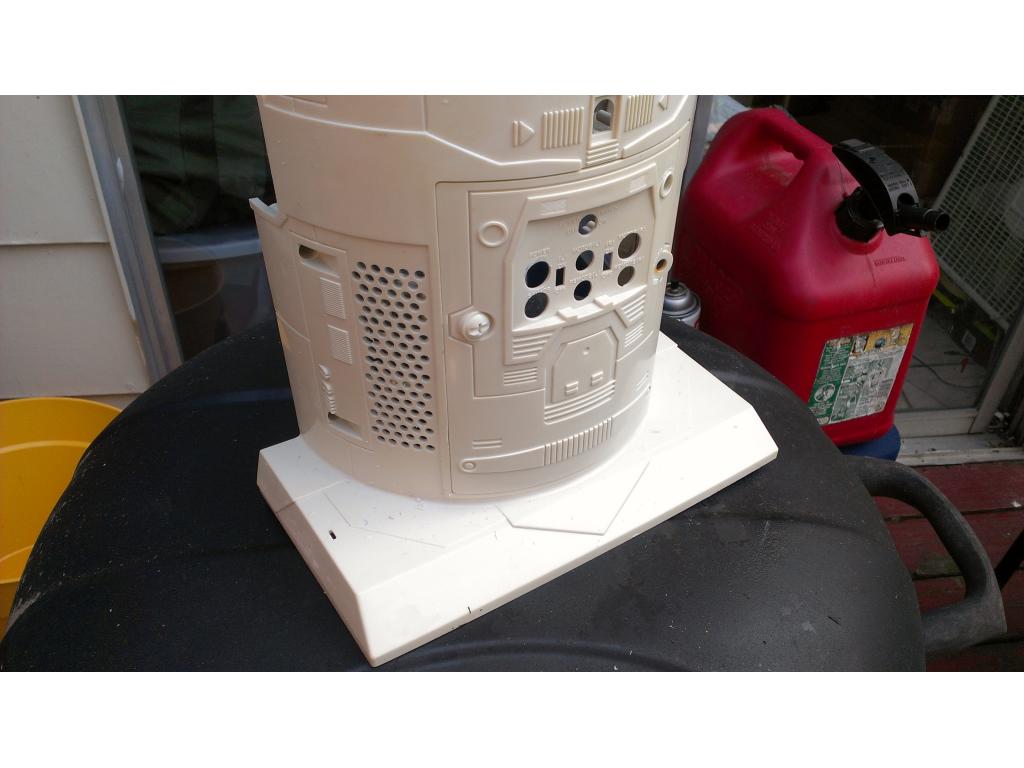
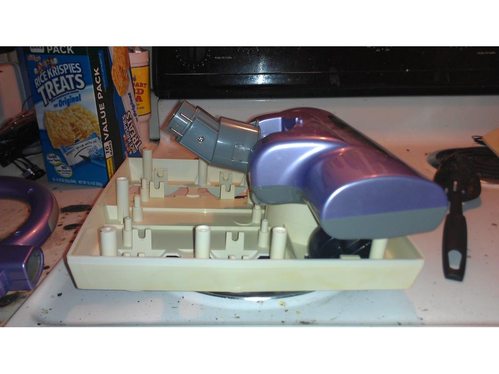
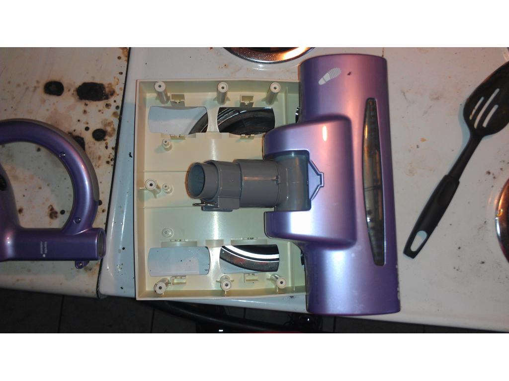
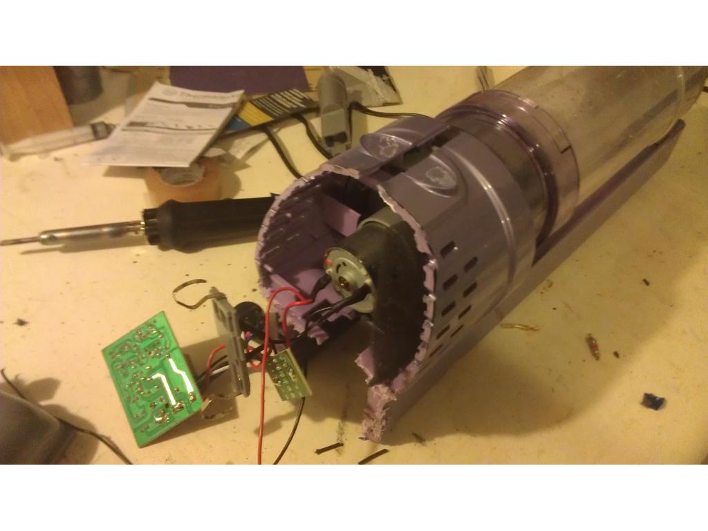
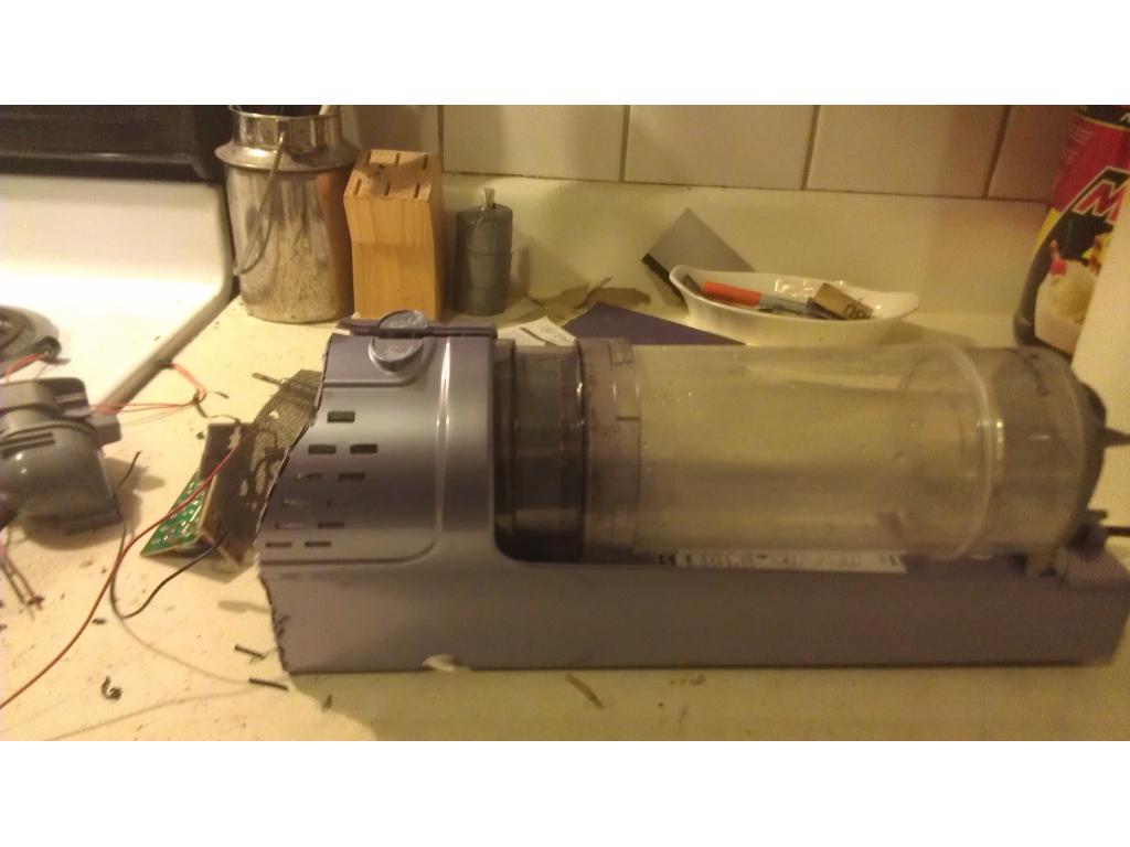
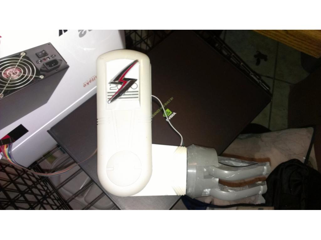
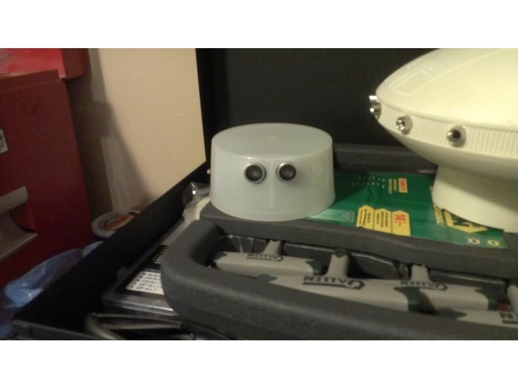
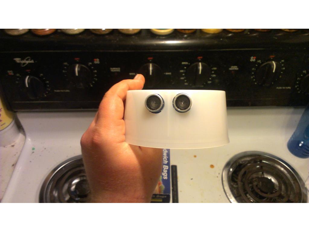
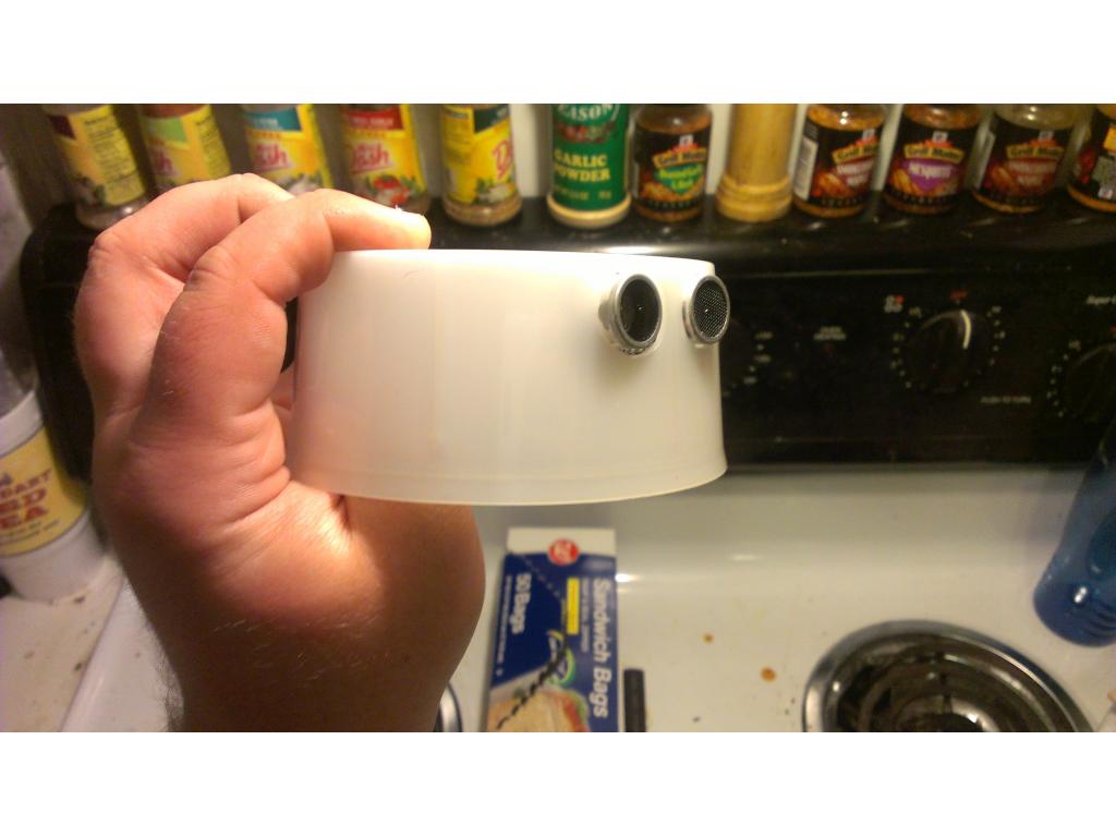
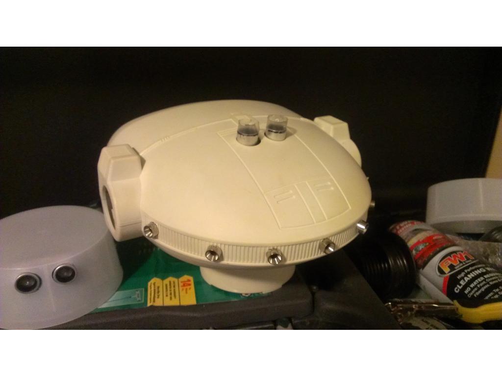
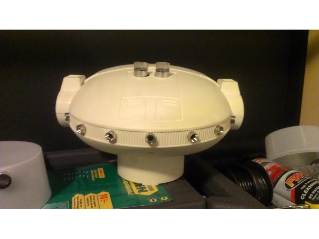
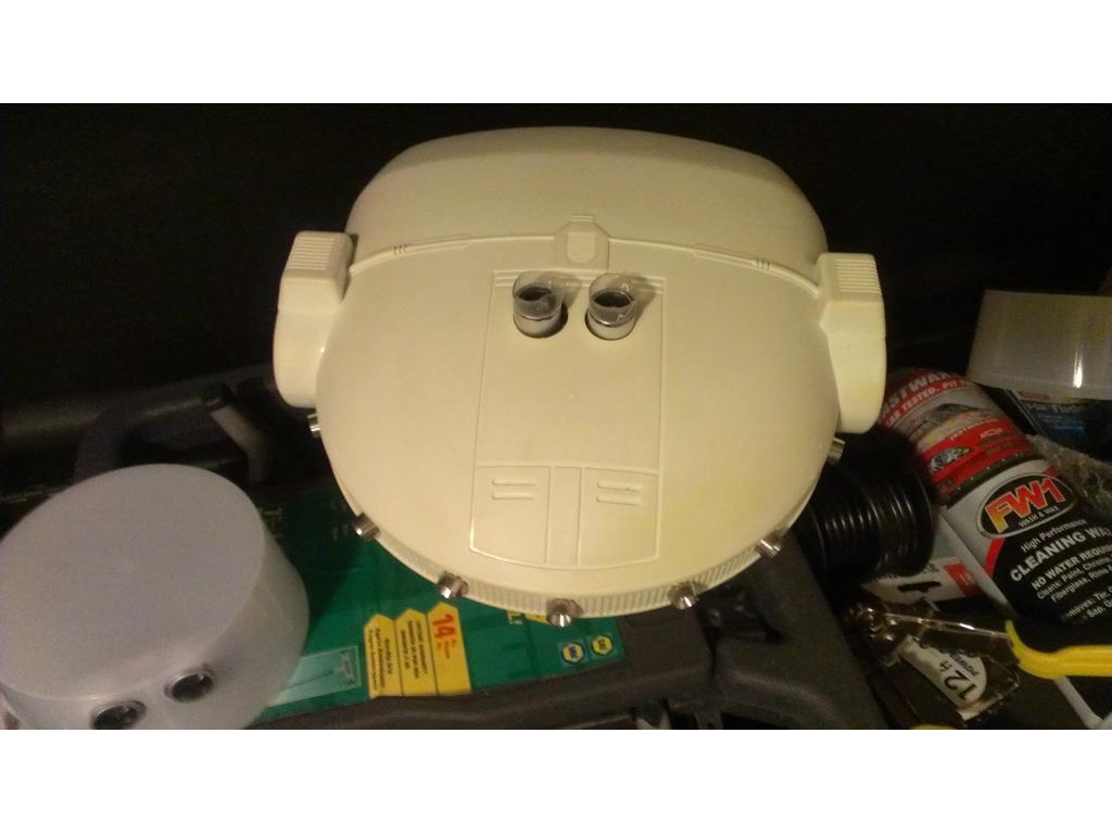
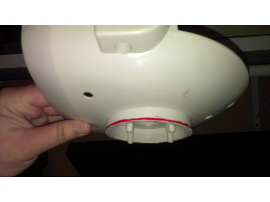
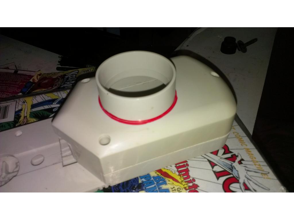
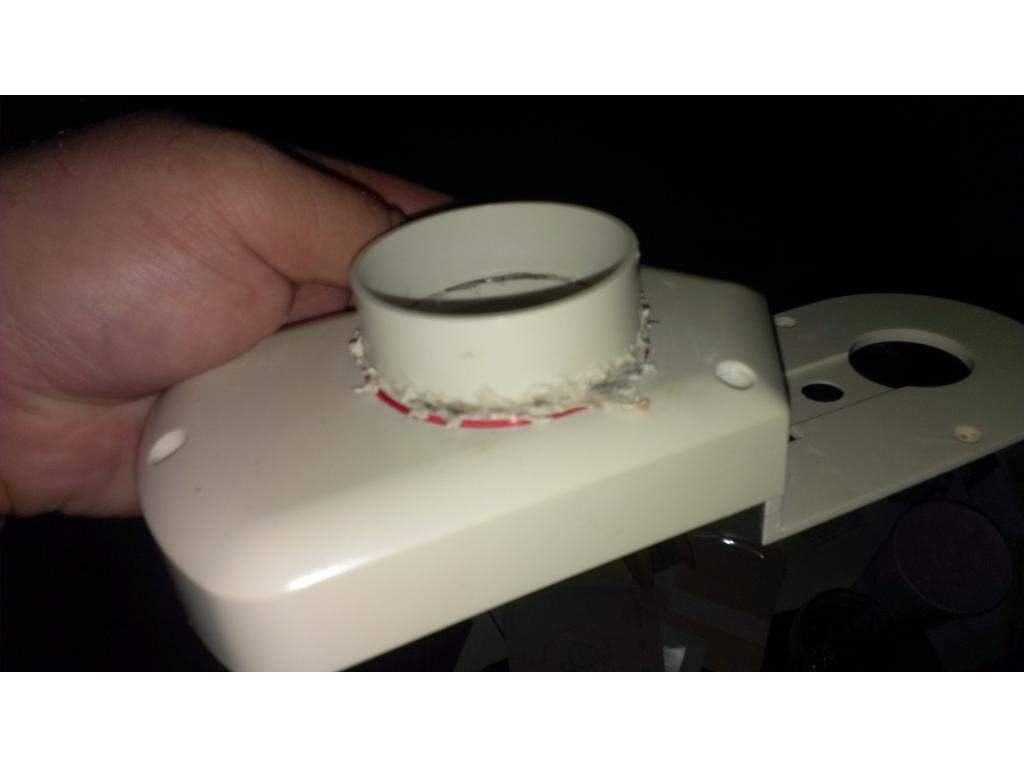
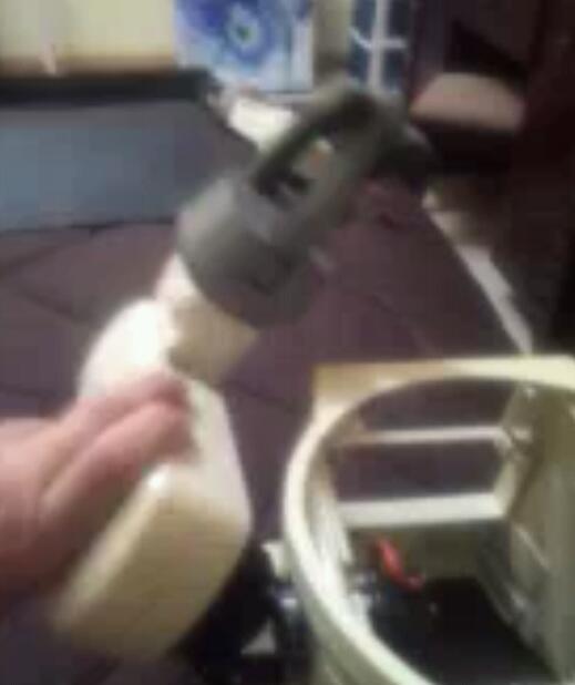
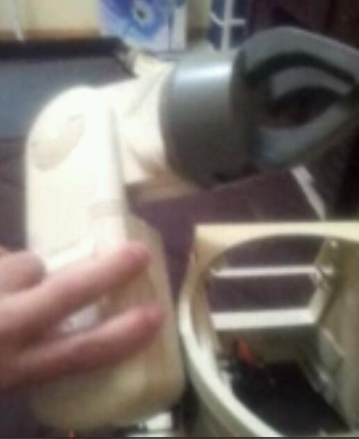
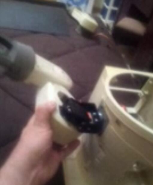
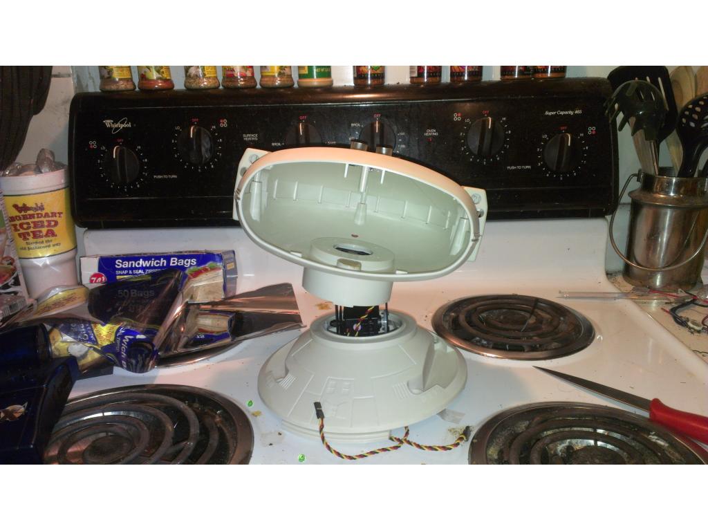
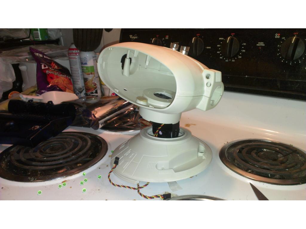
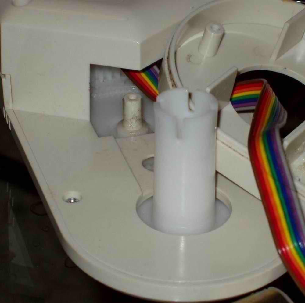
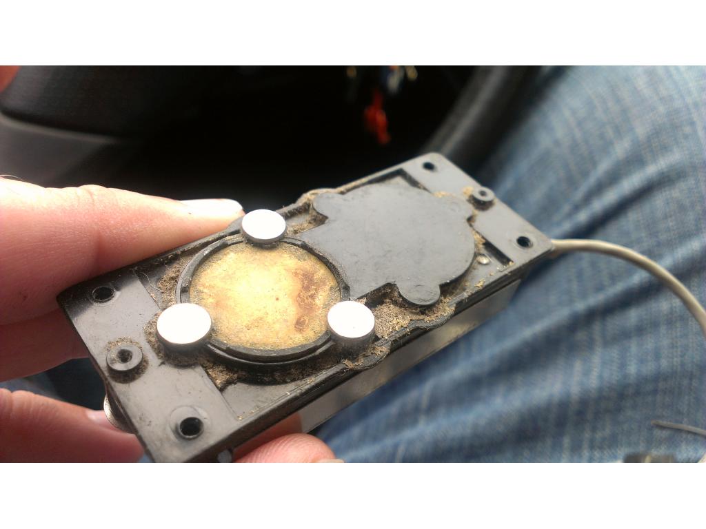
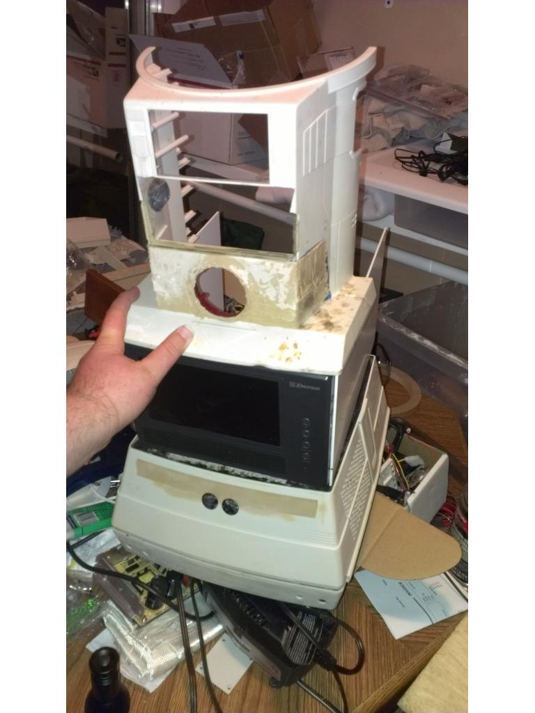
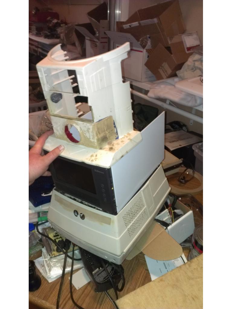
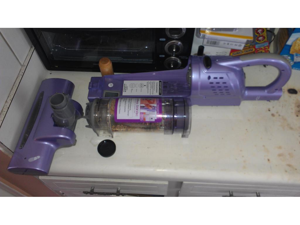
After measuring a bit I need to loose 2-3 inches from this canister and 2-3 inches from the casing above the vacuum motor / blower . Thats over 5 inches shorter because the canister and motor needs to fit into the back of the bot. No doubt customizing the back of Omnibot 2000 upper torso to include this and also route the vacuum hose down to the power head under the bot will all be challenges of fiberglass and hot glue engineering lol. I have not descided which voltage to power the vacuum with but I believe I will use straight 12v from a dedicated battery seperate from the main systems. The power head motor uses 11.1 volts and so does the vacuum motor. Running them at 12v I don't believe will be any significant difference. I may experiment with running the vacuum motor at 6v as well to see if I can make the system around 40 to 50 decimals so that it is not so darn annoying. I have three adjustable step down converters on the way. Also I havevs ideas for a wet mop that too but one thing at a time.
I changed what computer I'm using to somthing with a lot more power. It's a new motherboard just released from ASUS this month. Massive power , runs off 12v dc but only 39 watt http://www.ebay.com/itm/190500465148?ssPageName=STRK:MEWNX:IT&_trksid=p3984.m1497.l2649
The CPU I chose was AMD Athlon x2 dual core 2 GHz http://www.ebay.com/itm/260928442285?ssPageName=STRK:MEWNX:IT&_trksid=p3984.m1497.l264
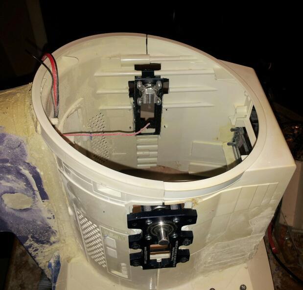
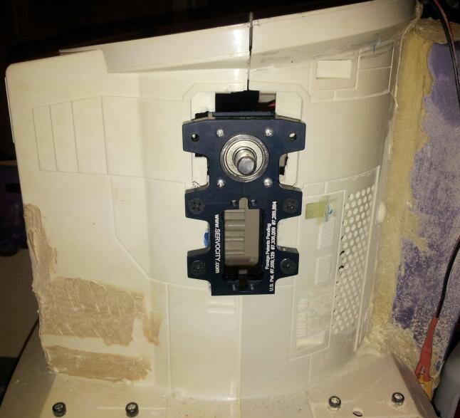
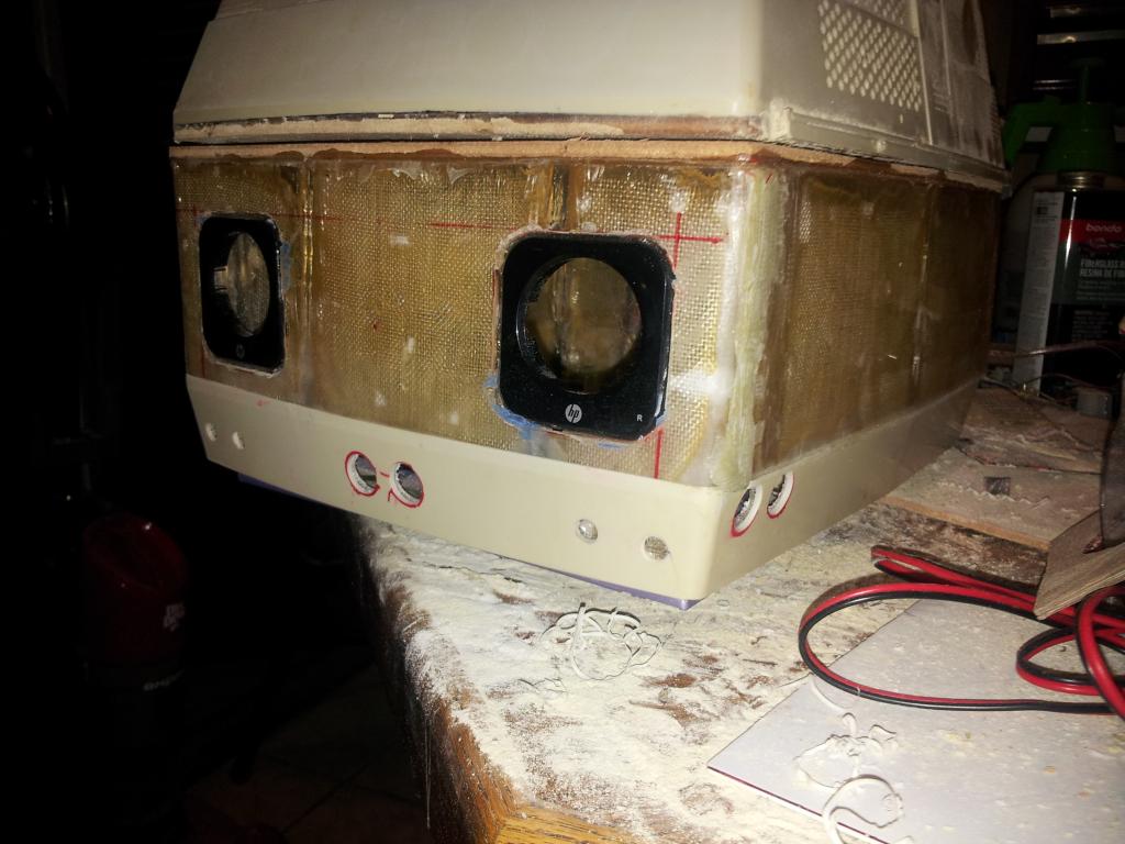
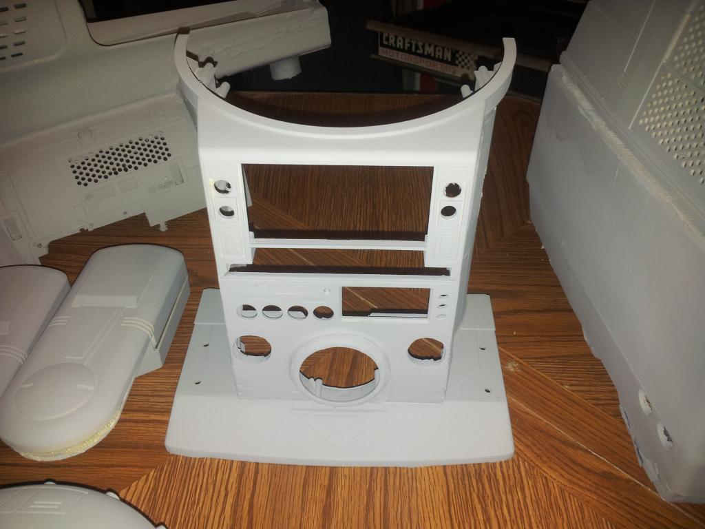
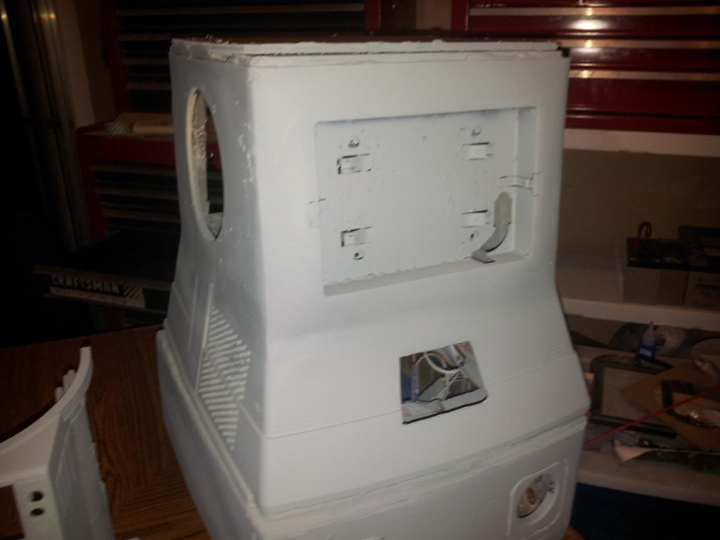
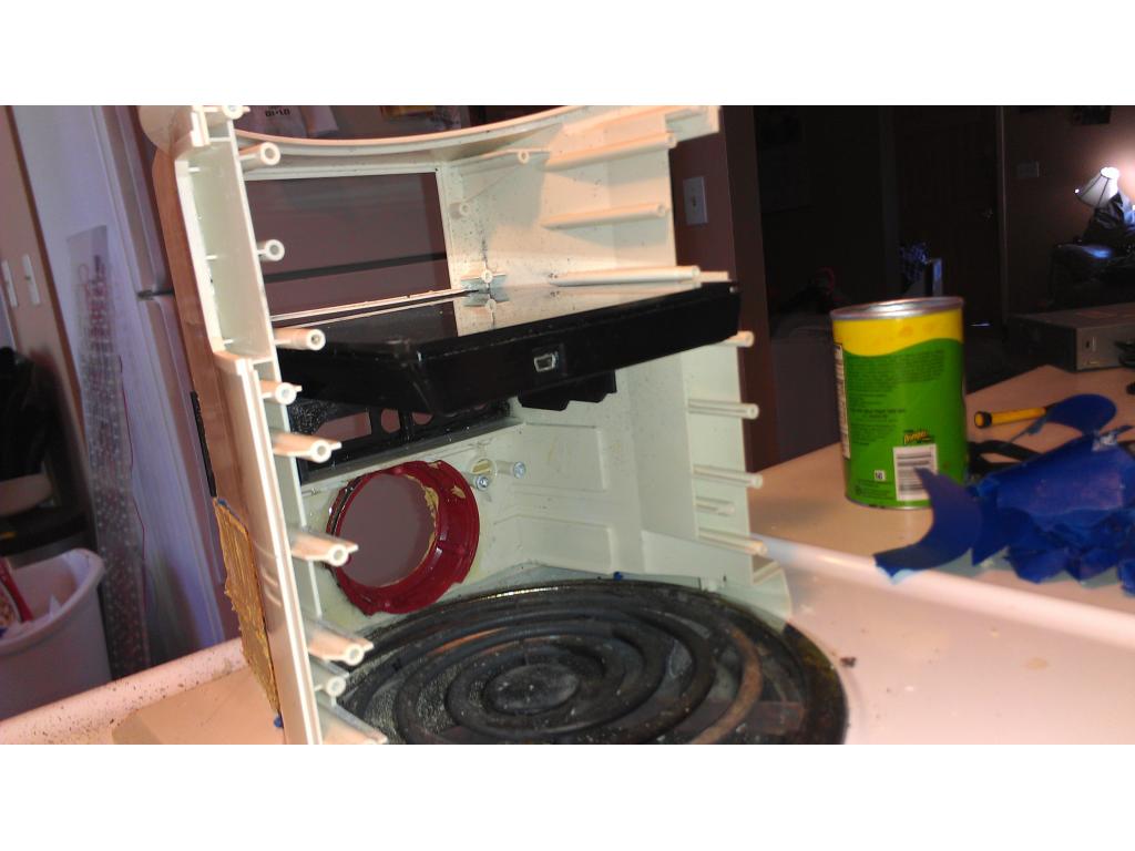
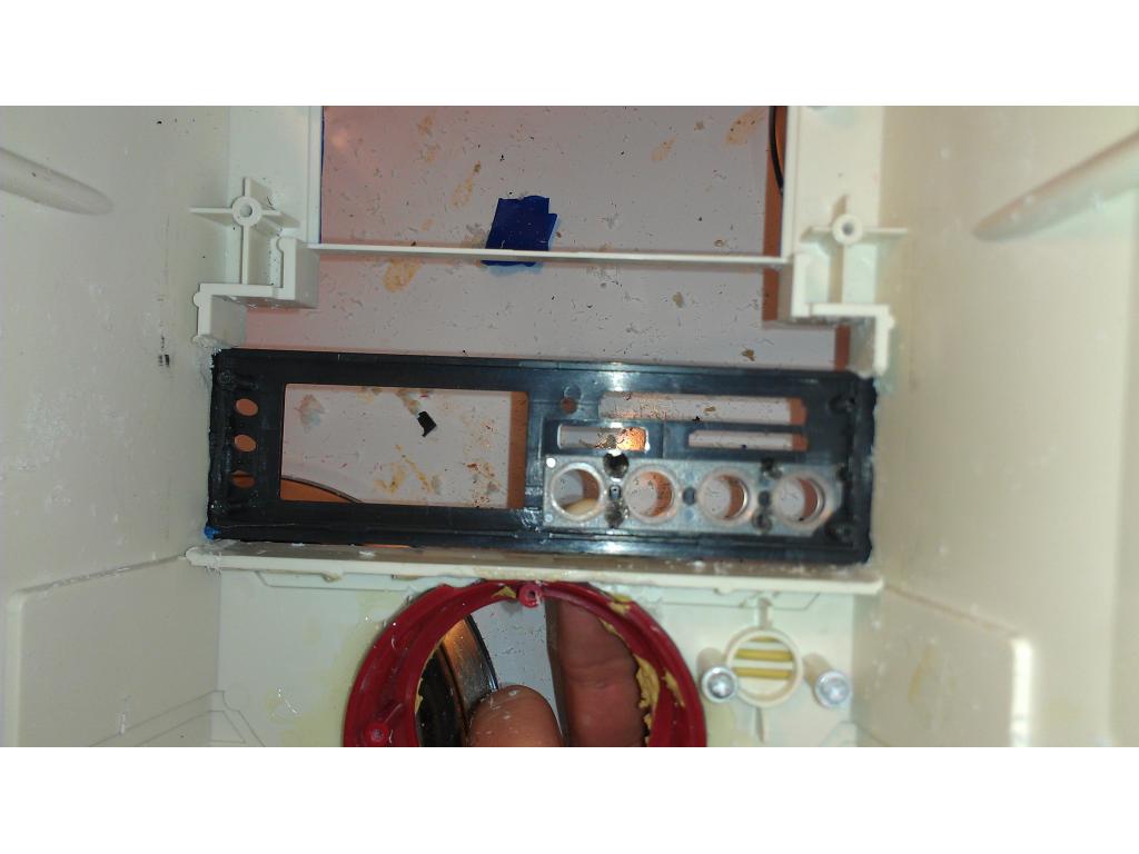
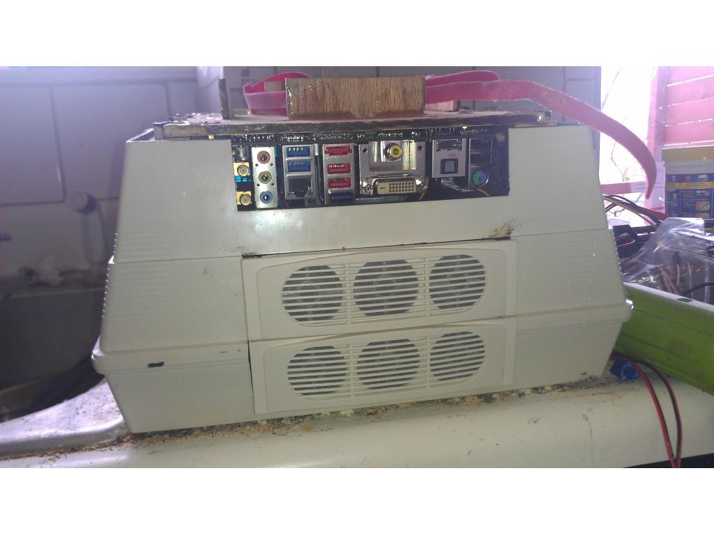
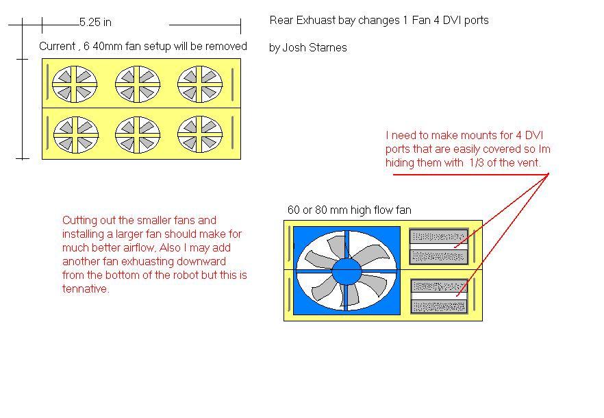
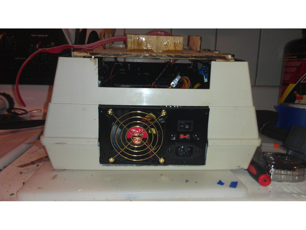
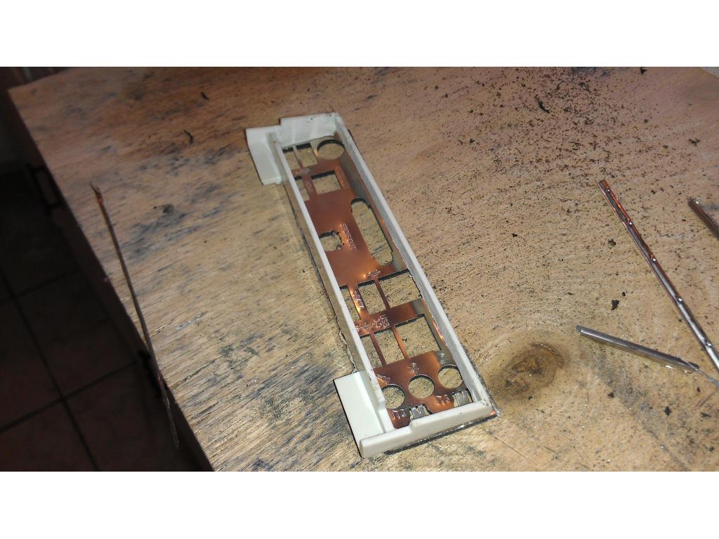
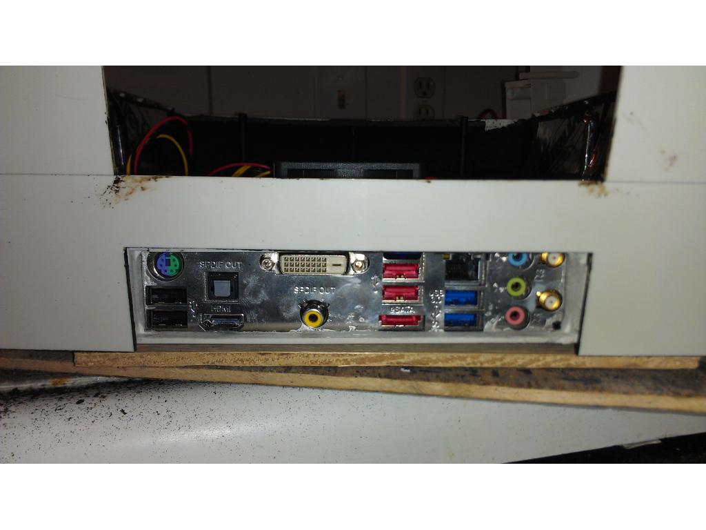
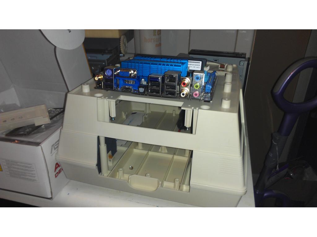
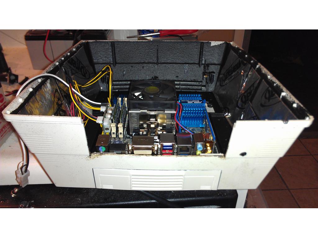
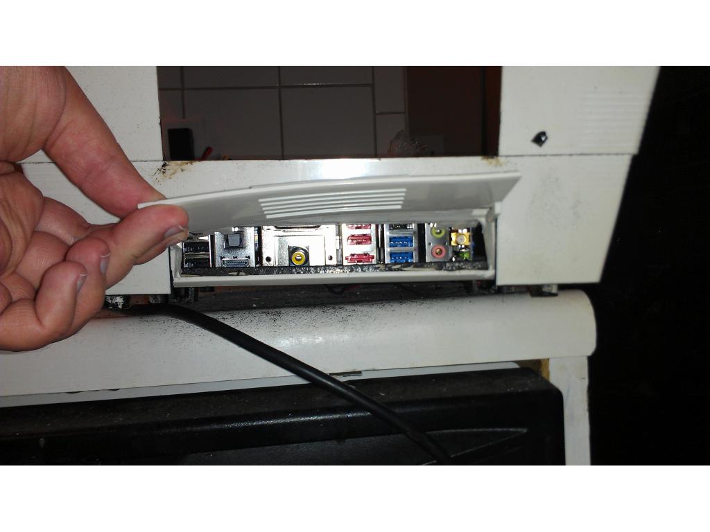
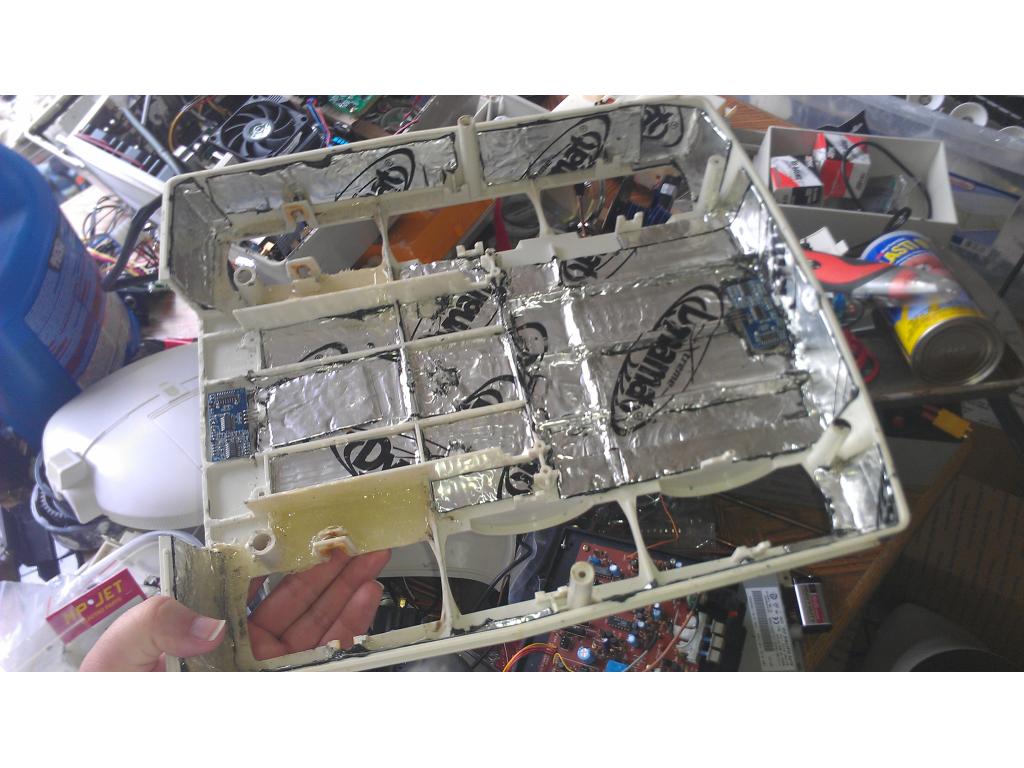
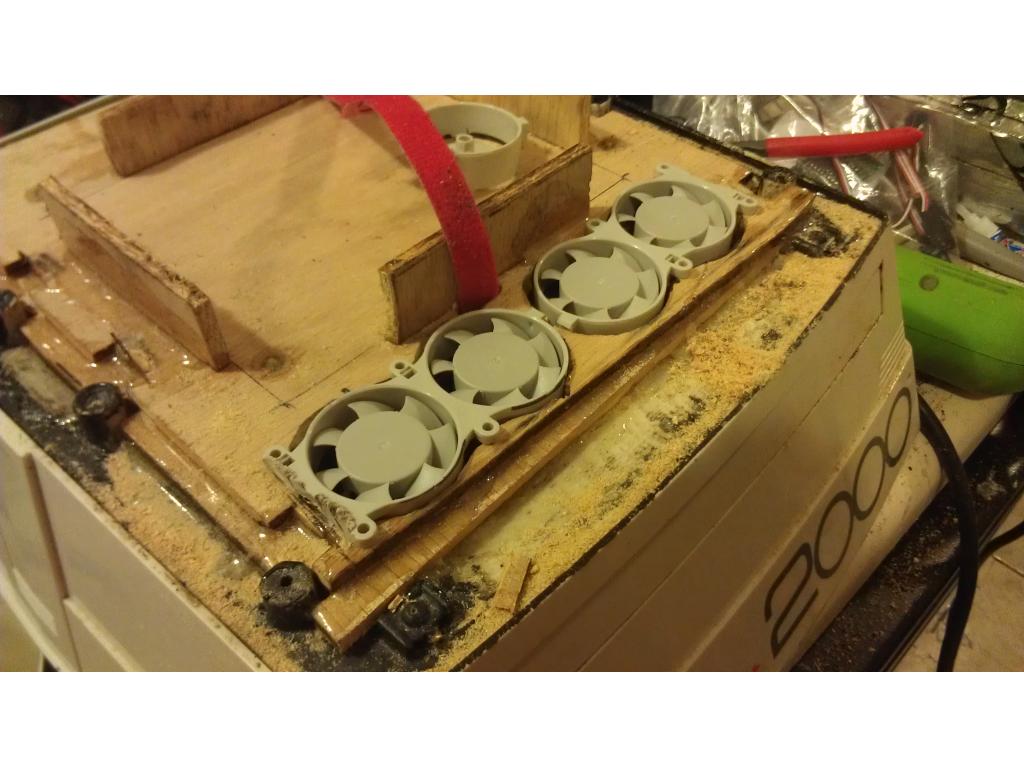
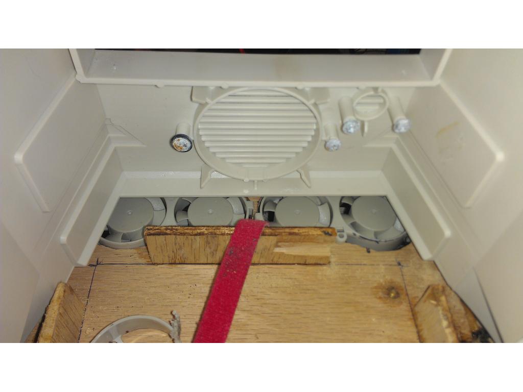
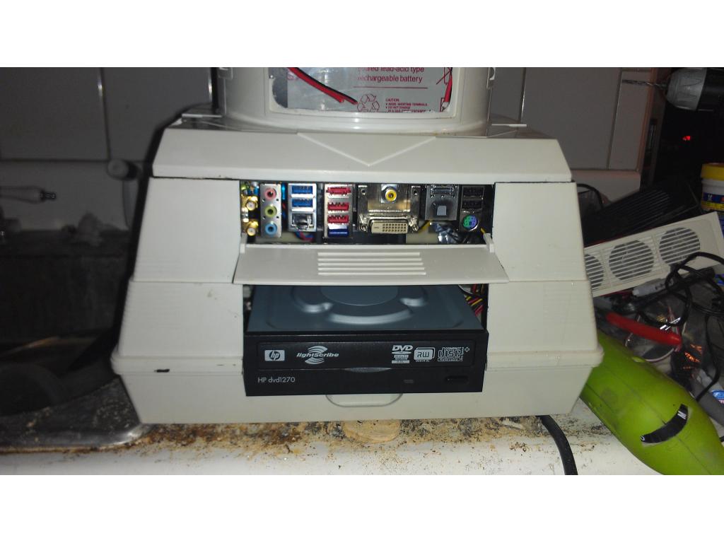
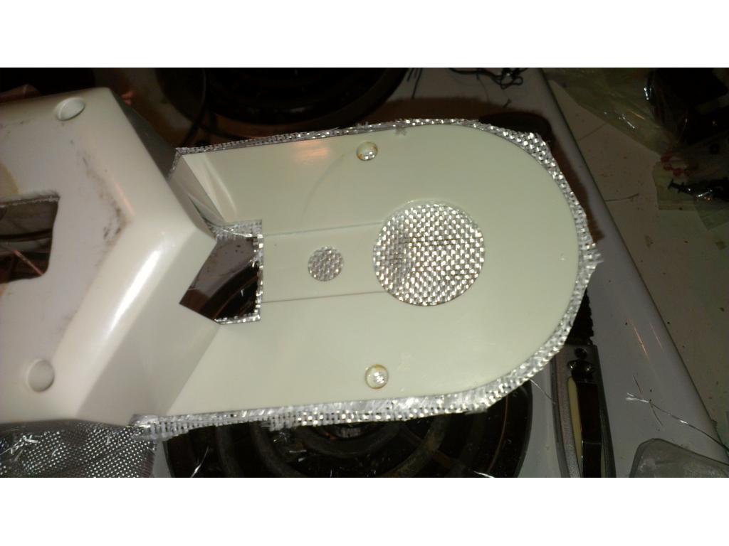
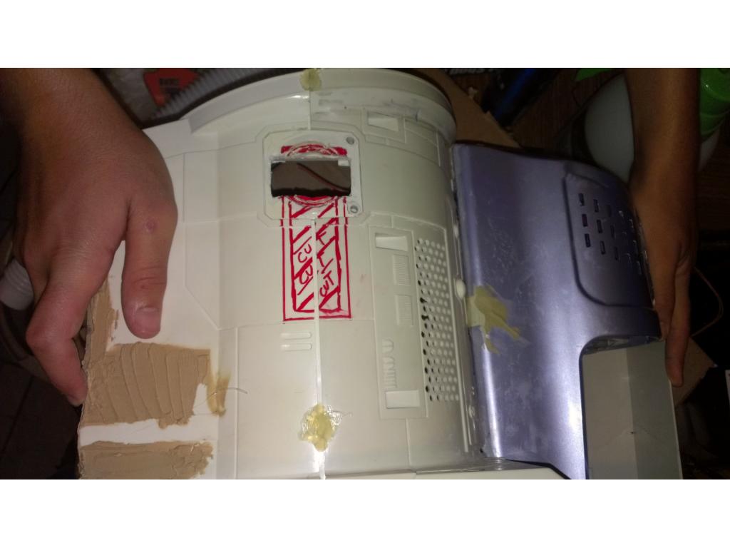
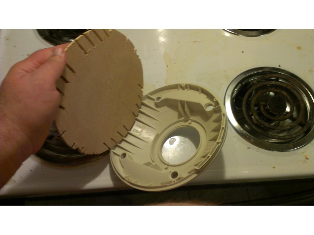
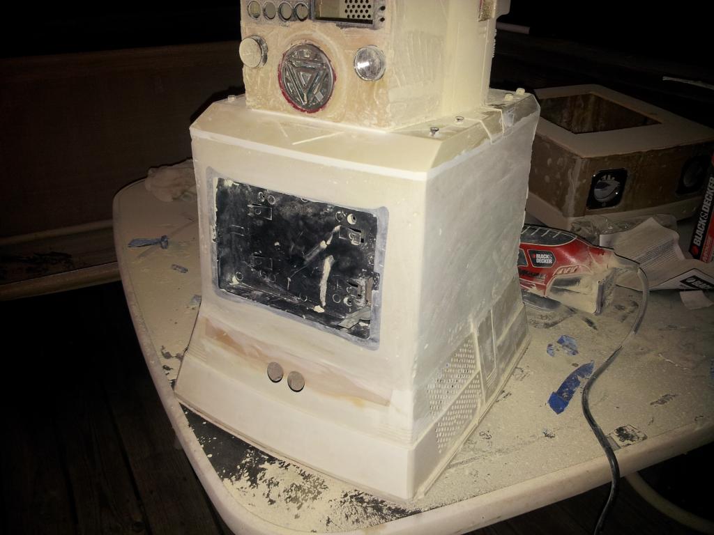
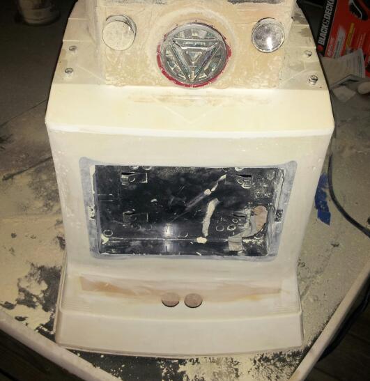
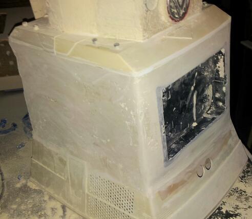
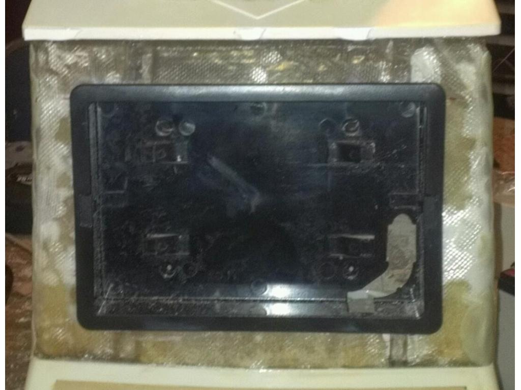
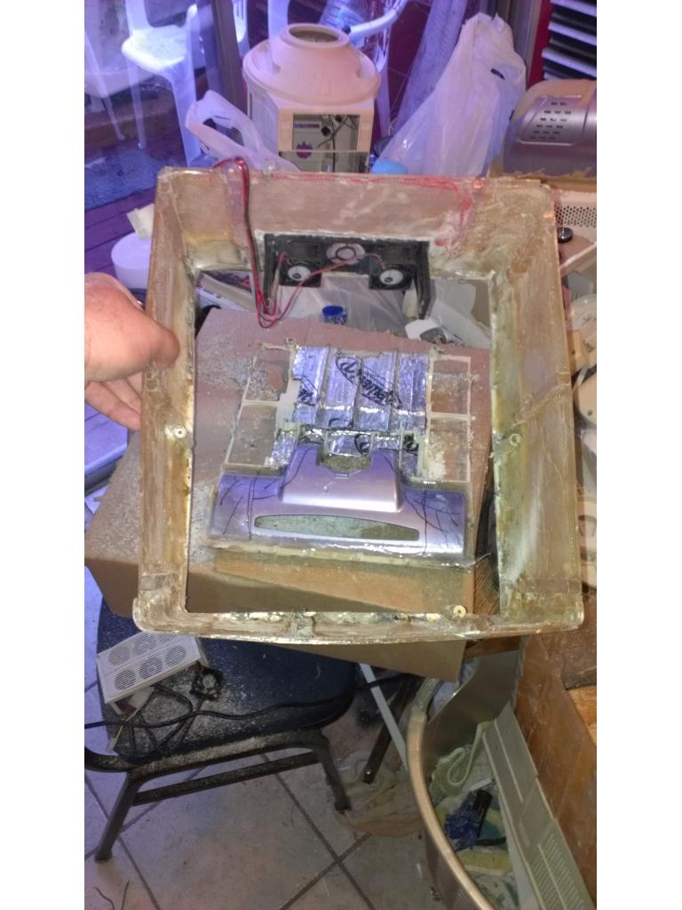
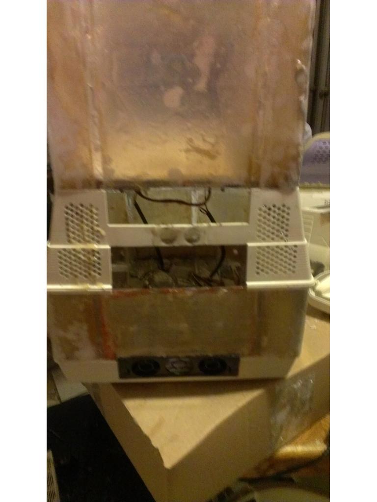
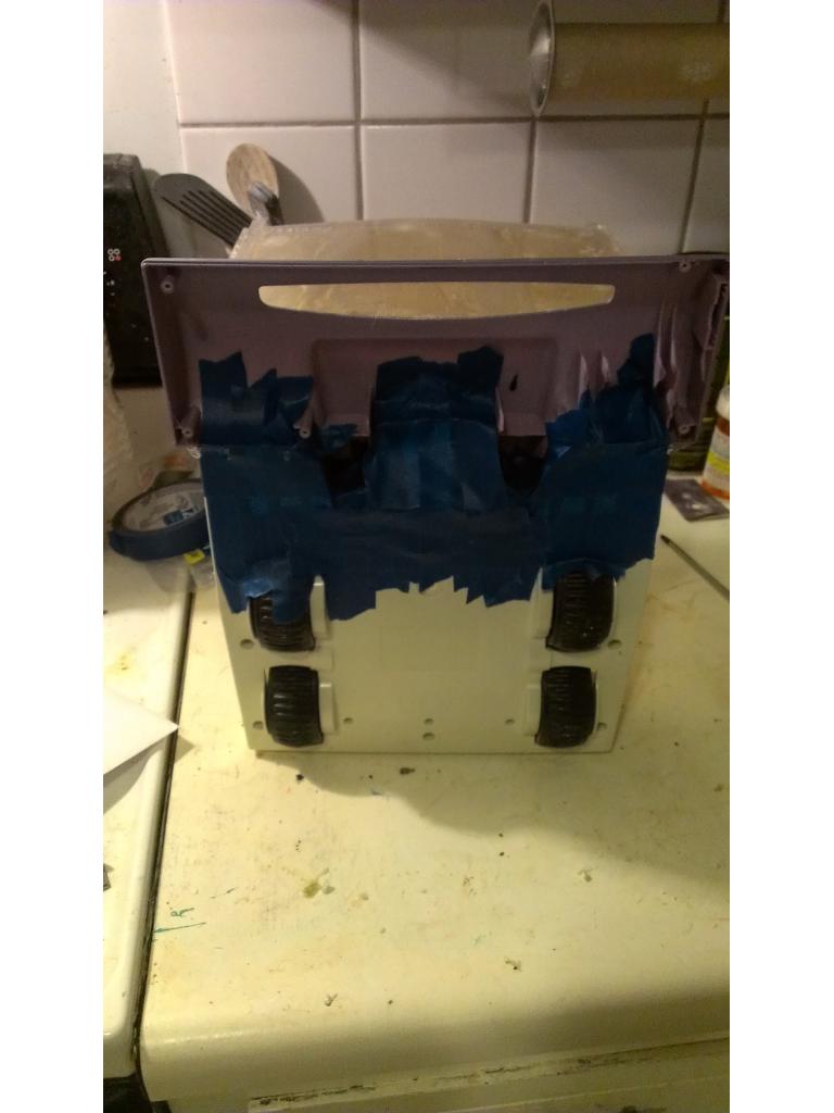
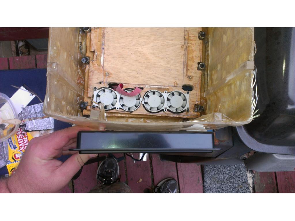
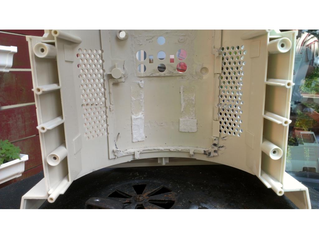
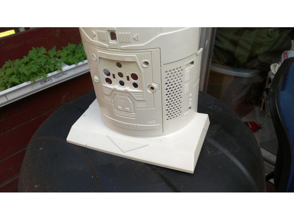
Here everyone can see I hollowed out the accessories panel in the back of Omnibots base. Lucky me its just about perfect to have a flip down access door to all the pc connections. I had to cut away the two posts that screws go through which were both hollow. It still is not aligned perfectly. I will cut away a hole the size of the board and recess it to make my connections and this door line up right. The are where the drawer was I believe I will install two 5.25 in bay hhd fans each one has three 40mm fans that move about 5 cubic ft a min. With 6 of these tiny low current guys I'm moving at least 30 cubic ft a min away from my electronics. I will have at least 3 identical intake fans in the chest , also a 5.25 in triple fan bay cooler. Testing battery fitment where I was thinking of installing two 12v 8.5 ah 6 pound batteries.
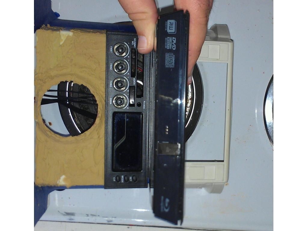
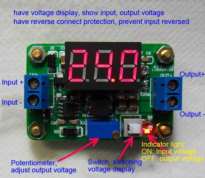
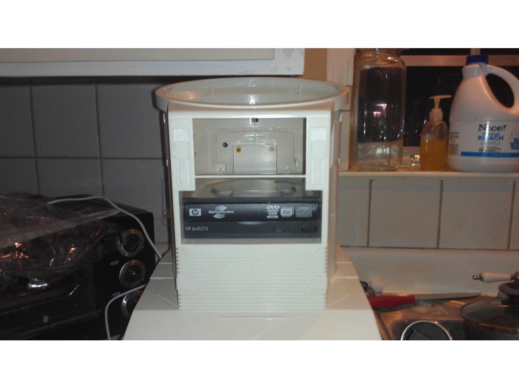
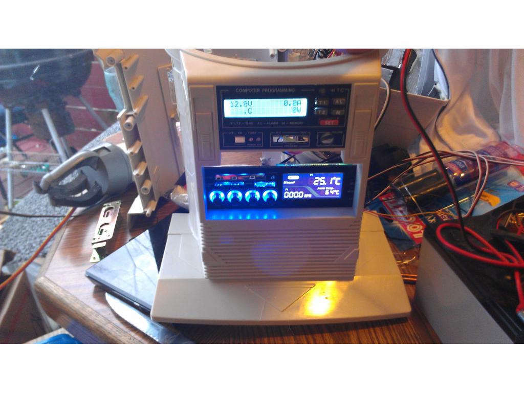
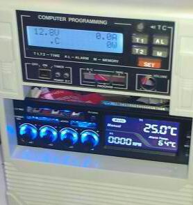
Though I have a slim blueray drive on the way it looks like my new HP lightscribe drive fits right at home above the two battery mounting positions. I have a Digital readout to install on the front for motor temp , wattage , current draw , and live battery voltage. That will fit at the top of the chest I believe.
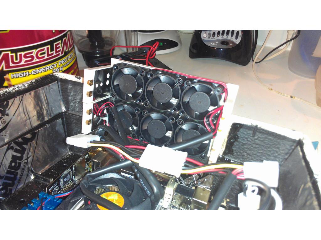
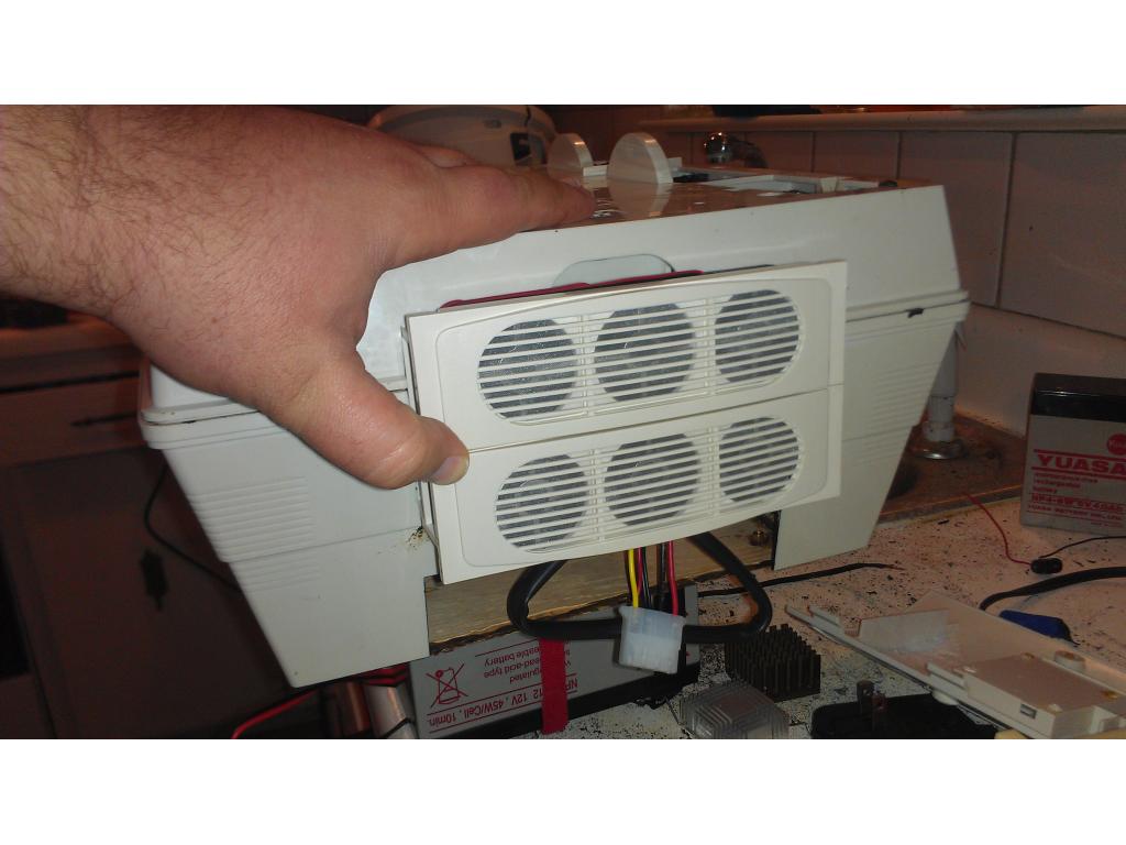
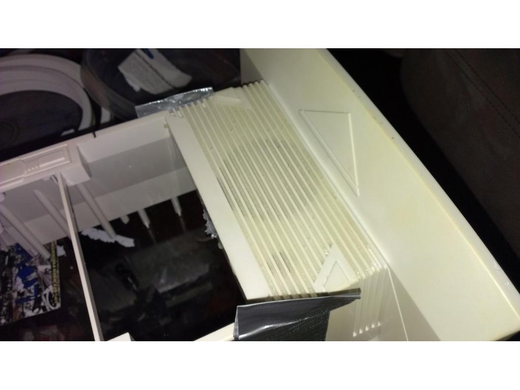
This is the bay fans I was talking about
Black bay fans I'm using http://www.ebay.com/itm/260928442285?ssPageName=STRK:MEWNX:IT&_trksid=p3984.m1497.l2649

This is one of the black.ones.but I have.2 more.that.match the Omnibot color perfectly. These are 40mm x 20mm triple set of fans. I believe.they move 5 cubic foot a minute per fan .
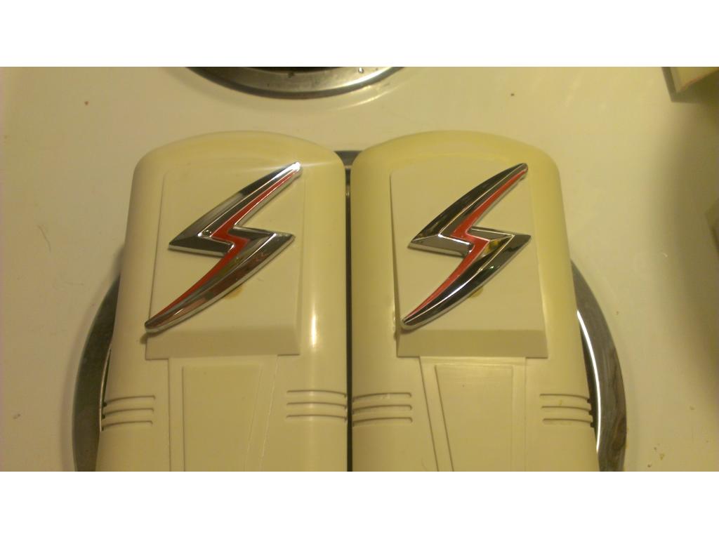
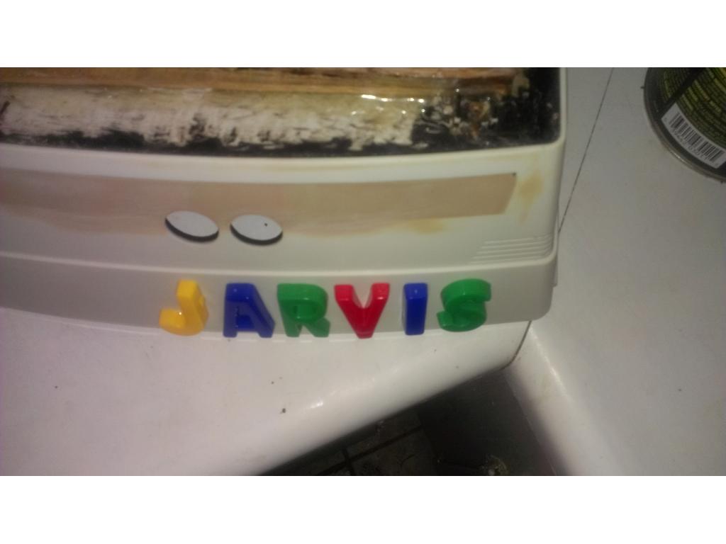
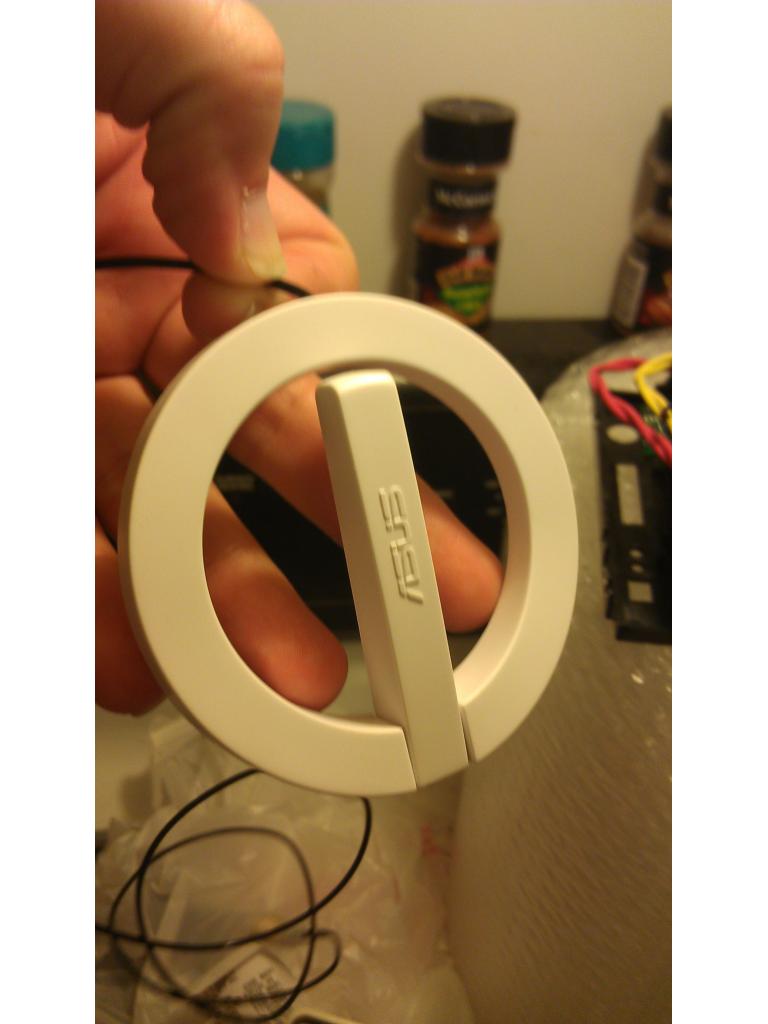
This is a Silvia Nissan logo , its first letter of.my.last.name , .if I ever paint this I will.definatly use.these.badges.Sick! He is looking Sick! I love what you are doing. What if you made the bot taller instead of the vacuum shorter?
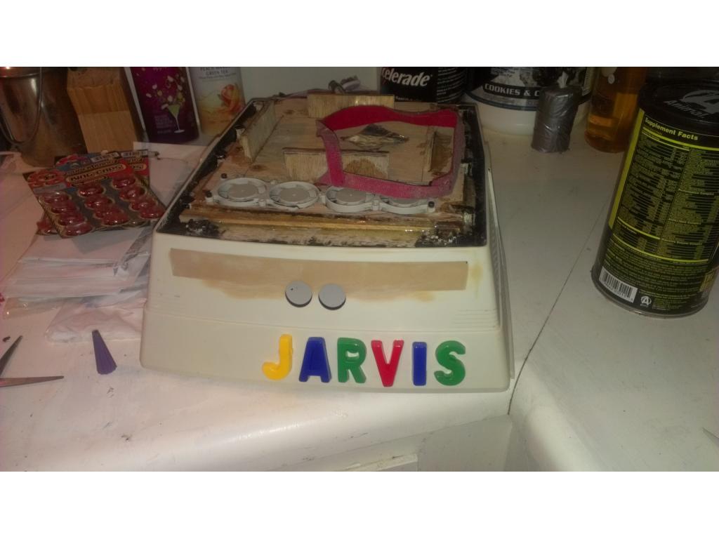
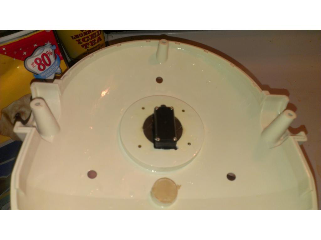
To answer everyones question that I have been emailed .... The motherboard is being mounted upside down. I'm making a battery mount that fits in the bottom of the torso with wood , motherboard will mount to the bottom of the battery tray , I will cut away a section of plastic the size of the motherboard. This will recess it 1/4 inch to line up correctly with the accessories door I hollowed out for the pc connections. Mounting the motherboard upside down is more practical because you can only access it by removing the bottom of Omnibots chassis. This gives me a few crucial inches to upgrade heatsink or add a high end video card later , but right now I believe onboard graphics are rated to handle 1080P Blueray decoding and HDMI which is what's important to me
@bret that's a great idea , I could turn the base /bottom of omnibot upside down , it should be the exact shape of the top of 2000 base , maybe that would add 2 to 3 inches?? Or I have more 1/4 in plywood , I could make a spacer I guess. Hmm I need to get the board n other stuff mounted first. If I add a spacer section then I will definitely need to do some painting. It could add some extra space for drives /fans too though , hmm. I will definitely consider this.

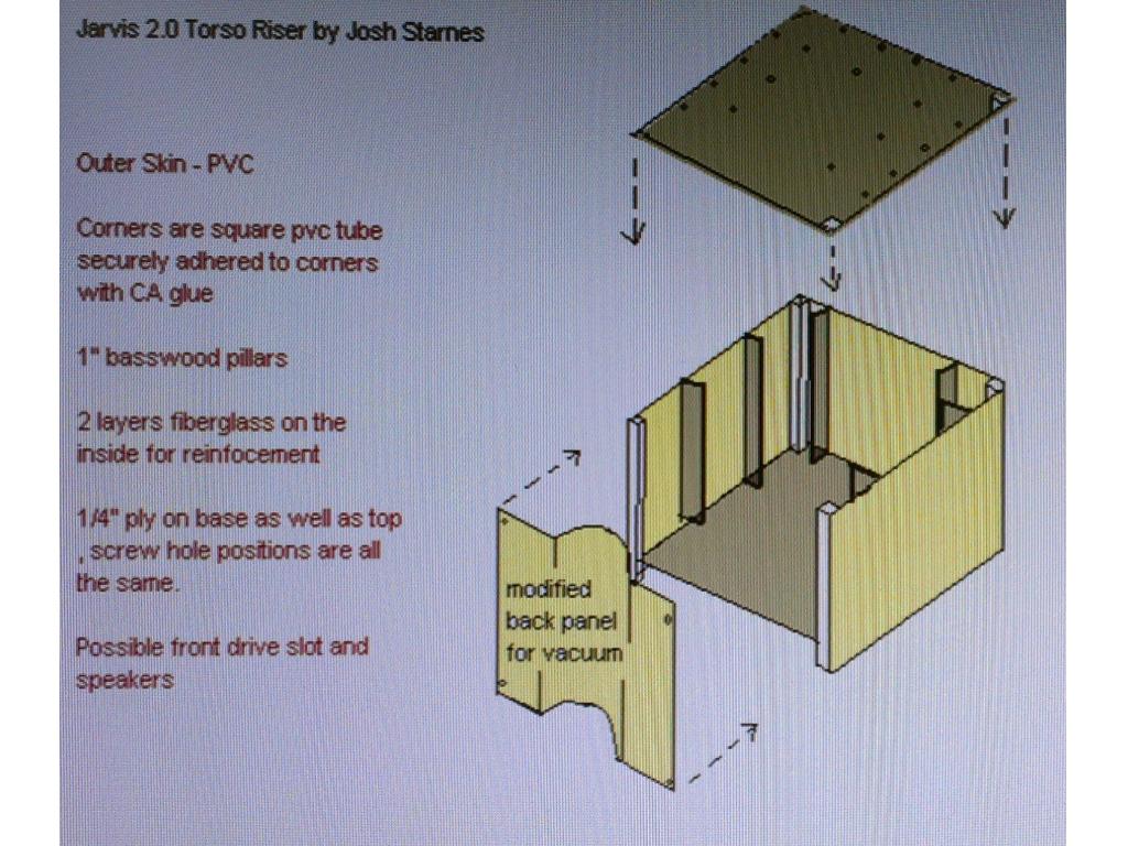
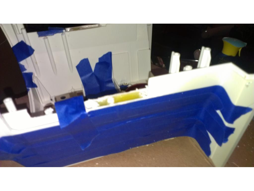
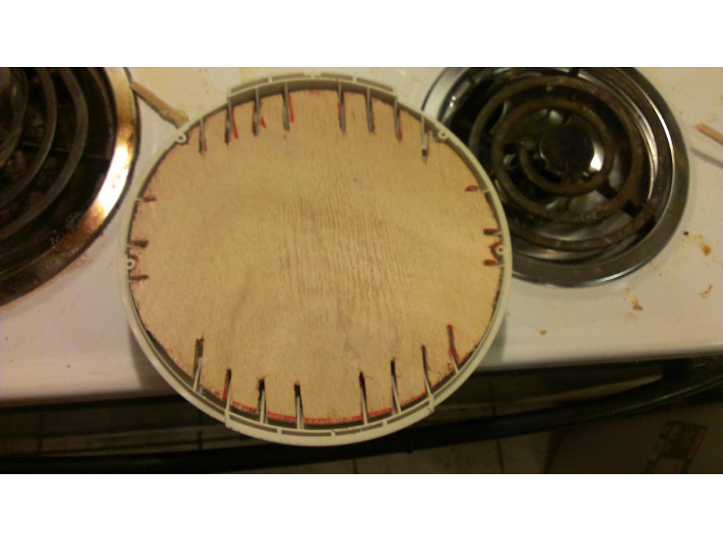
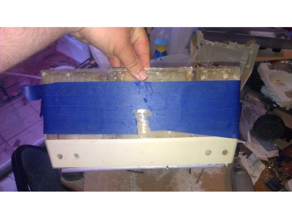
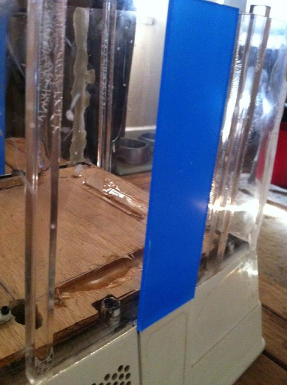
Ok I modified a backoff panel and cut down all sides with my dremel. Then glued it to the accessory door. First time I glued it upside down..... Oops lol. I removed it with a razor and flipped it around. I'm hoping all plugs clear but more cutting can be done if needed.
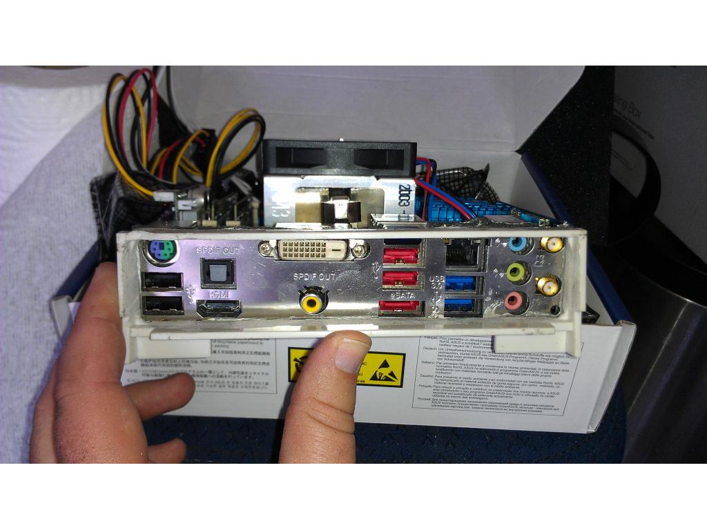
A test fit
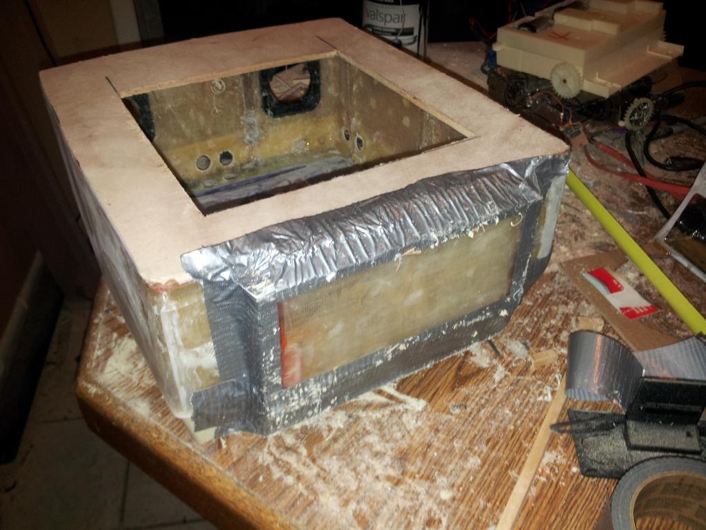
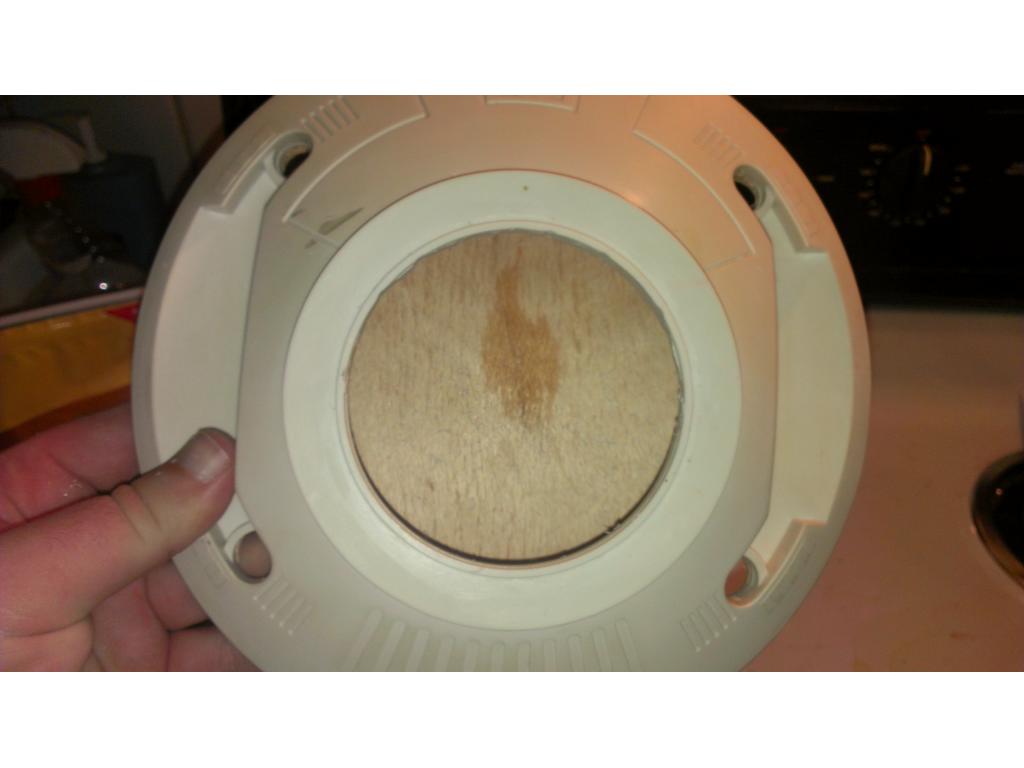
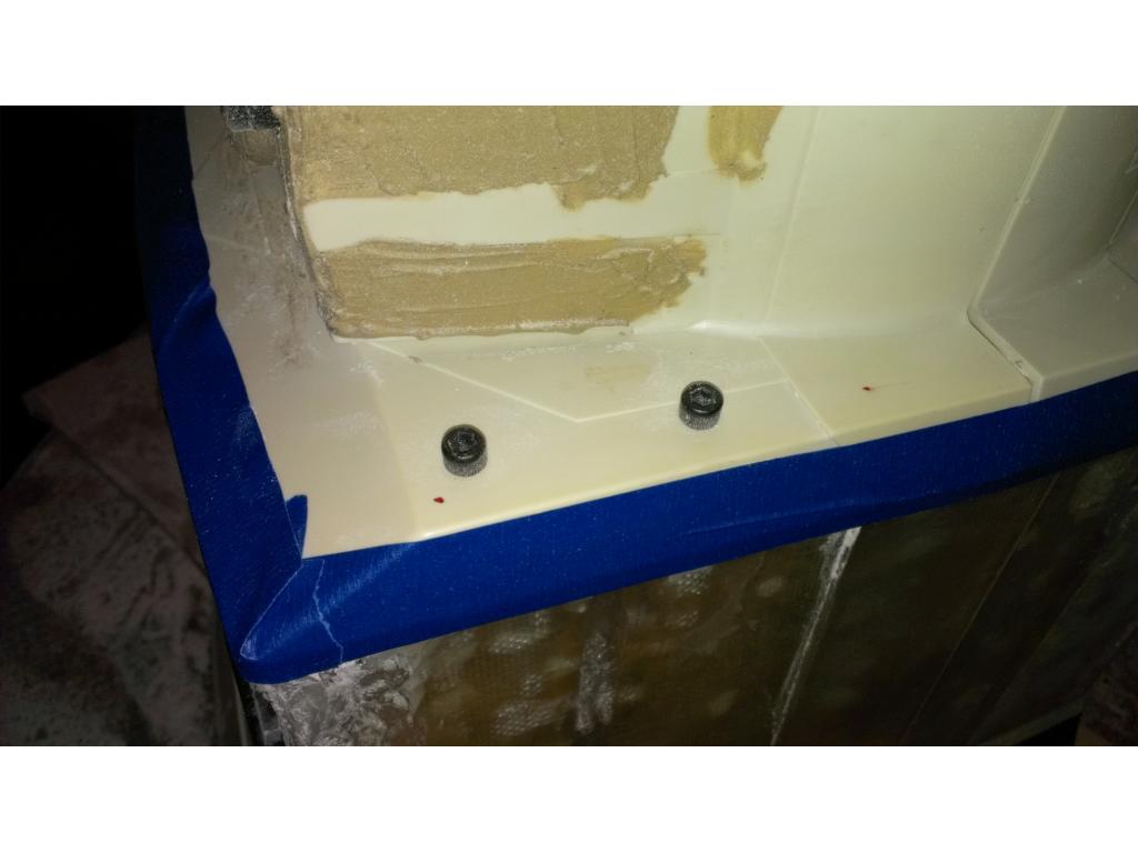
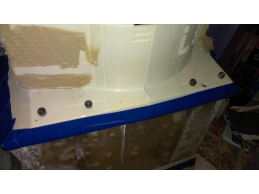
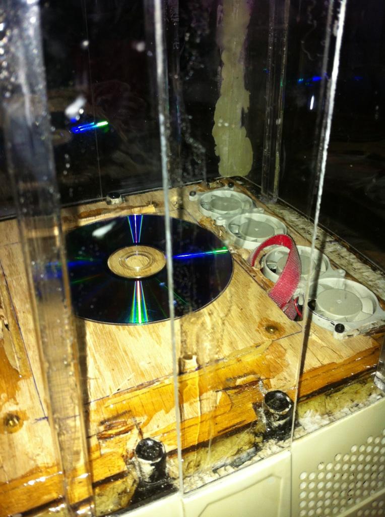
I glued in 4 brass stand offs that the motherboard mount to. They are in mini itx configuration so if I ever upgrade boards its a easier swap. The stand offs put about 1/8th in gap between the bottom if mini itx motherboard and the wood. I plan to epoxy this wood on both sides all the way around to stuffing the Omnibot base to support the 12 pounds of batteries that will be mounted at the bottom of the torso.I have a idea here. I'm planning in mounting the ez board to one side of the base wall and motor controllers right beside them if I have room. If I don't I will mount the h bridge to the opposite side.
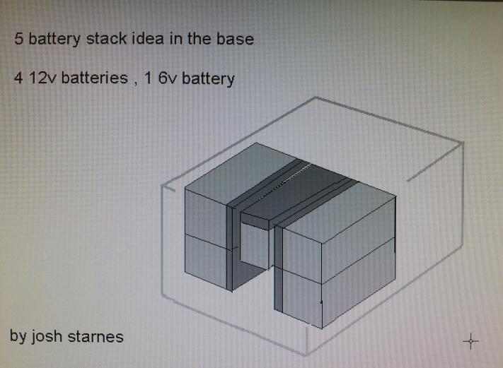
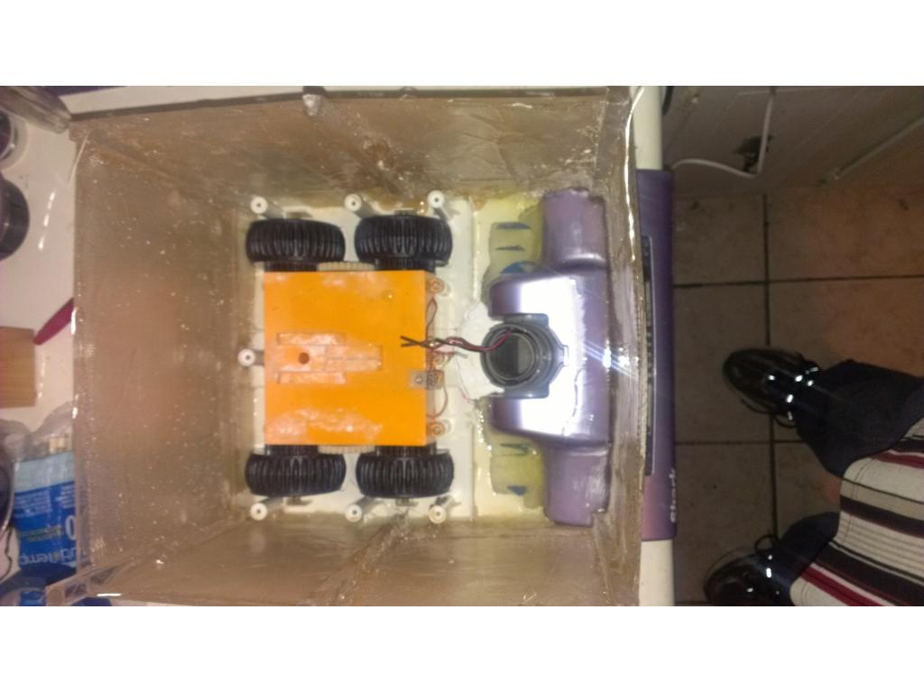
Ok just for fun I tested.how many batteries I could fit inside , I could fit one battery in the drawer , and 4 batteries in the bottom of the torso. Also one battery fit ontoo of the gearbox but that's completely impractical place to put a battery. So I have figured I could have a maximum of 5 yusa lead acid 12v 8.5ah batteries. That's 34 ah of juice , and 30 pounds total of batteries. With five batteries the platform would weigtht 45-55 pounds. More than likely I will only do three batteries. That's 26 ah and 18 pounds of battery weight. This feels like a weight the stock gearbox could lug around. Any opinions are appreciated! Take in mind I removed the 3 pound weight from the base and removed another 5 pounds from removal if the cassette player and stock motherboard.
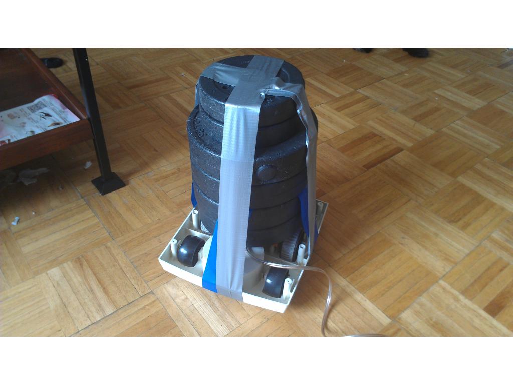
You may want to add some weight to the drive section and just see if those motors can move it. Remember you also have the weight and drag of the vacuum to consider.
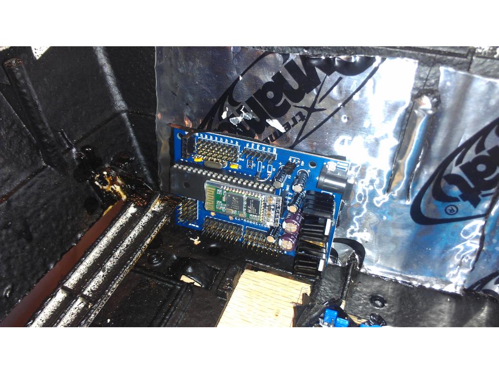
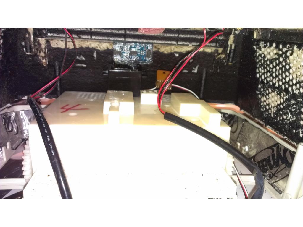
I'm going to get the battery tray done , mount up the fans , and mount up ezb. Right now I don't have a h bridge , it was accidentally not shipped with my ezb so all I can mount is the sonar and ezb, fans and batteries now.
Man it is really coming along! I really like how you are mounting it all in the bot. Looks professional. I still think you could add a spacer so you don't have to cut down the vacuum. I saw that someone else did it to 2000 that he painted black. It is somewhere in the forum under projects I think. He just used wood. Question Josh, If space is not a real problem and you already had one, do you think a standard ATX motherboard would be acceptable? Or is it more of a power issue?
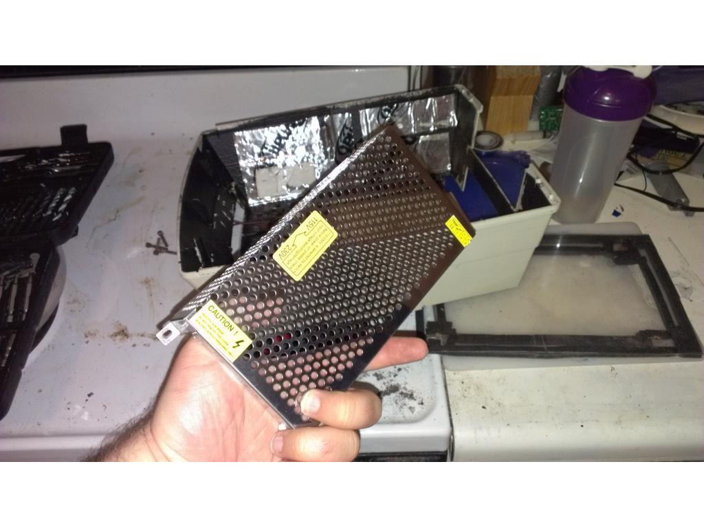
It won't fit a standard atx unlesss the board was mounted sideways . The power supply has to be a small one. There are 160 to 200 watt power supplies , mine litteraly is 1.5 in x 3 in and produces 160 watts continous. But really though there are lots of atom power mini itx boards that use way less juice but still do the job. I picked this board because with a simple CPU change I can go from 25 watts 2.0 GHz , but I can plug a AMD Phenom X2 555 quad core 3.4 GHz at a drop if a hat.

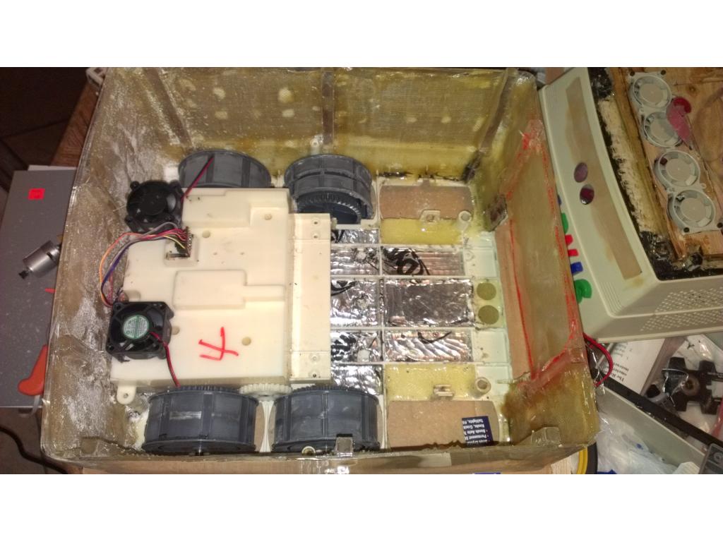
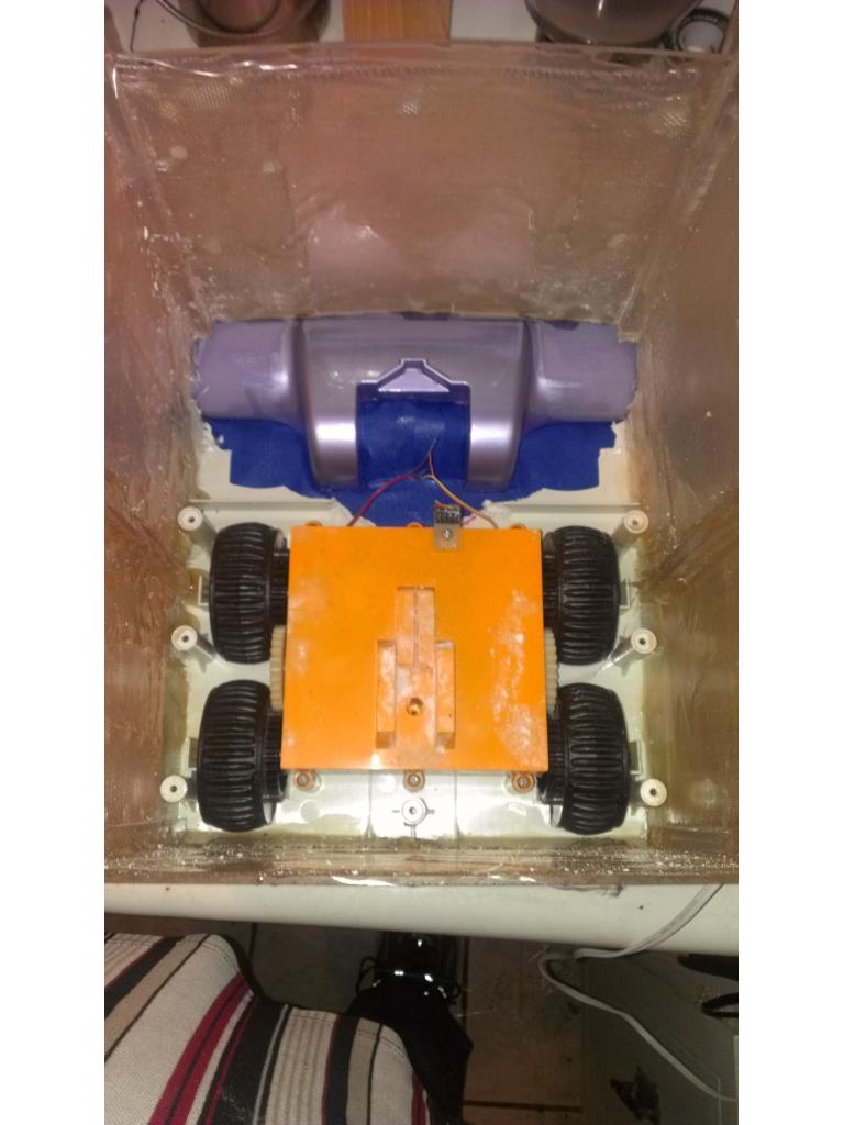
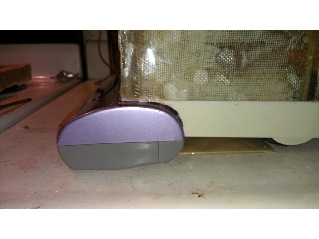
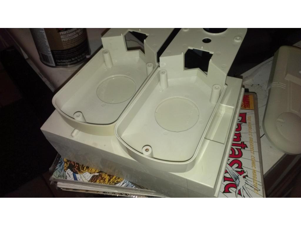
Ok so I made a battery tray for two 12v lead acid batteries , still room for a 6v ub645 if I needed a dedicated 6v battery. But I have those voltage step down controllers in the way. I used 1 in thick shims on all for sides of each battery and glued them down so the under no circumstances will the battery move. Then cut a 1/2 in slot and ran a Velcro strap through and that straps down the batteries so they don't move even if turned upside down. (yup I did it). I held up the two ventalation fans , I will be making the drawer hole larger to match the size of two 5.25 drive bays. I have several xt60 plugs I'm using as high amp battery connections. At this point I just need to find a good mounting point for the hhd and t coming soon a blueray disc drive. I also checked the vacuum power head vs the rear wheels which is where I thought of mounting the power head.Omnibot is going to have a full belly for sure ! J.W.
J.W.
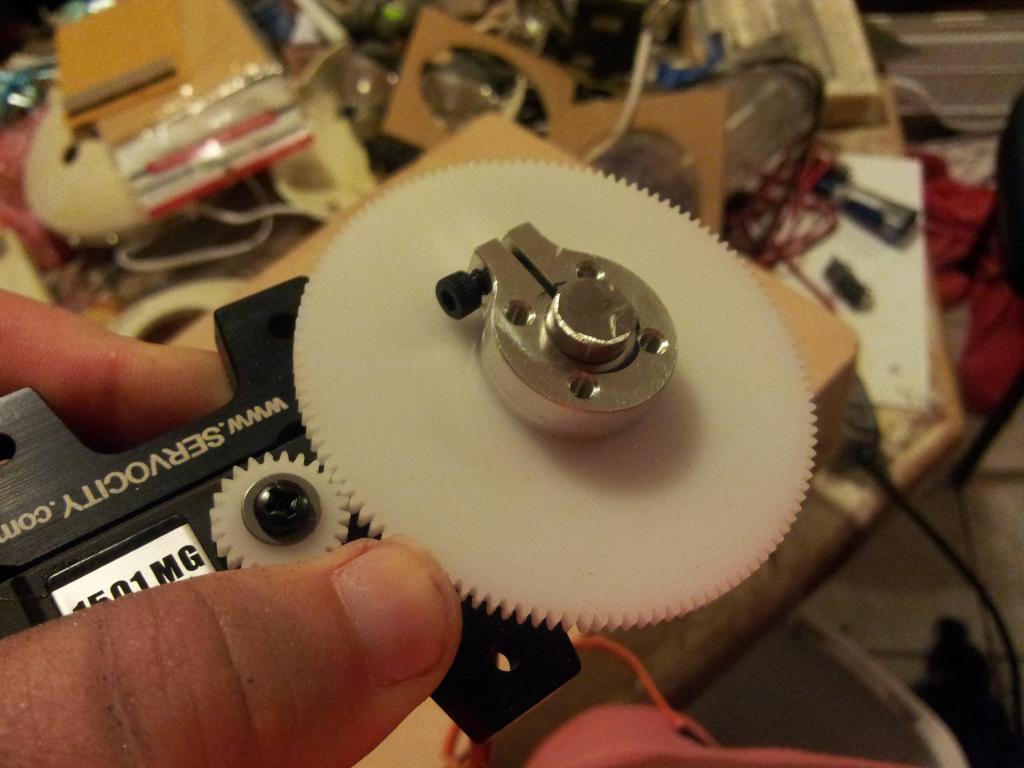
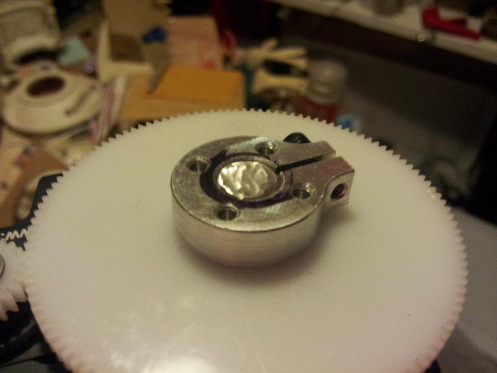
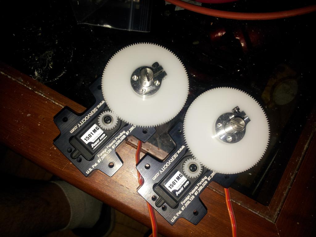
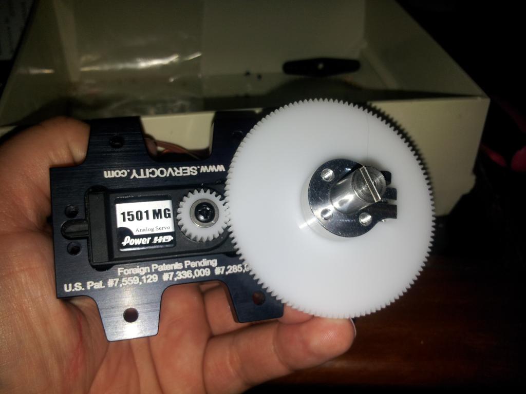
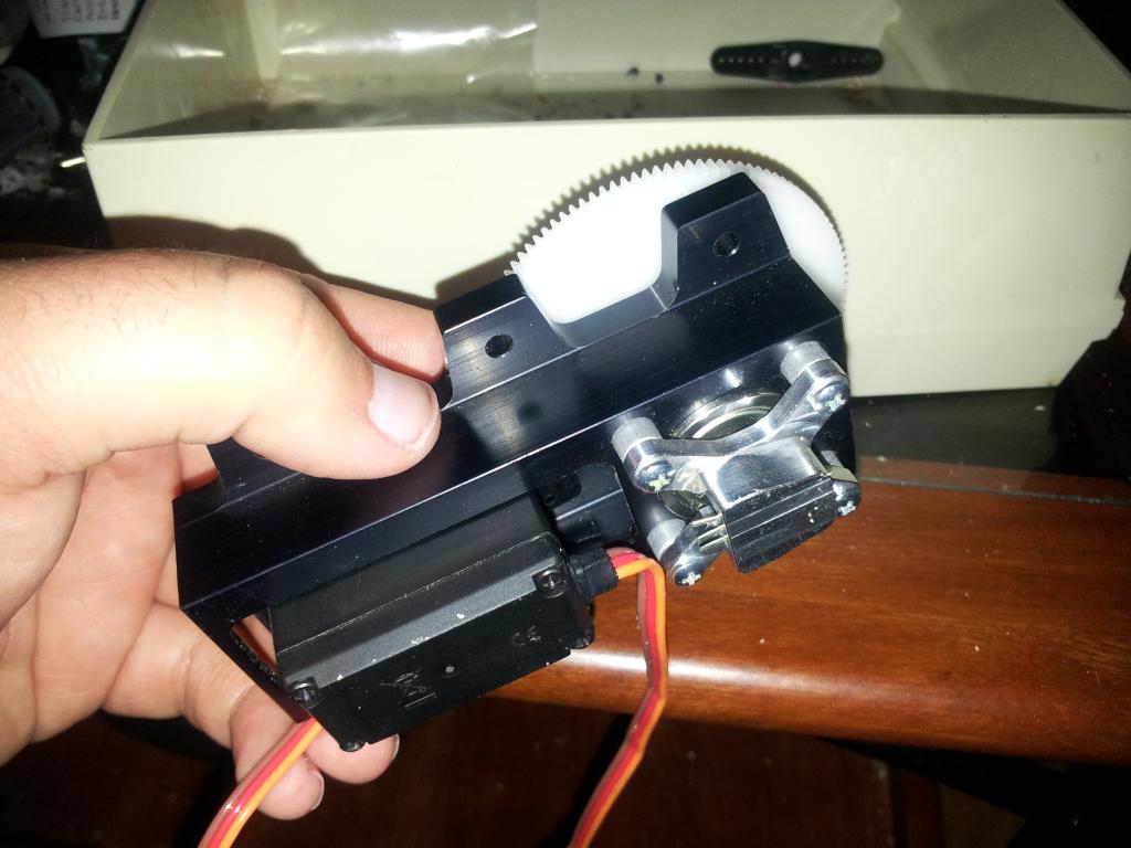
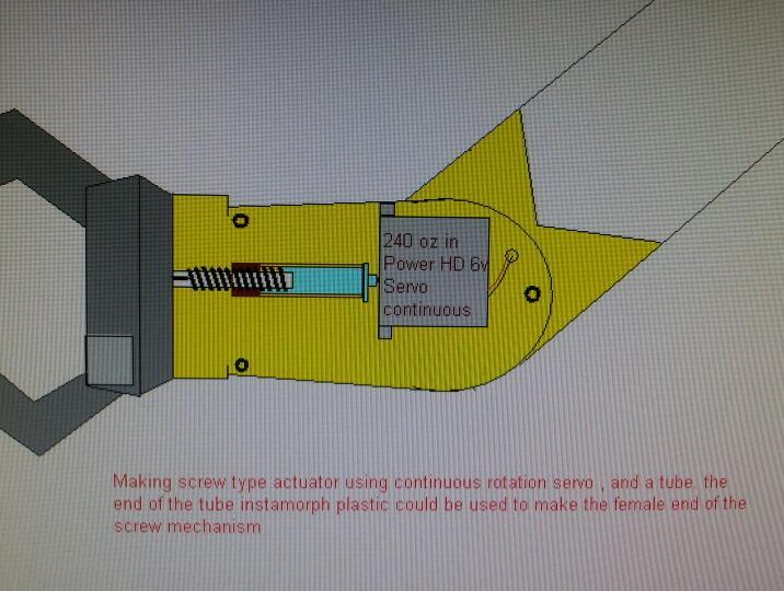
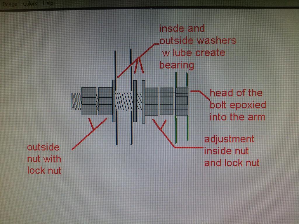
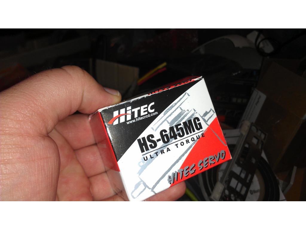
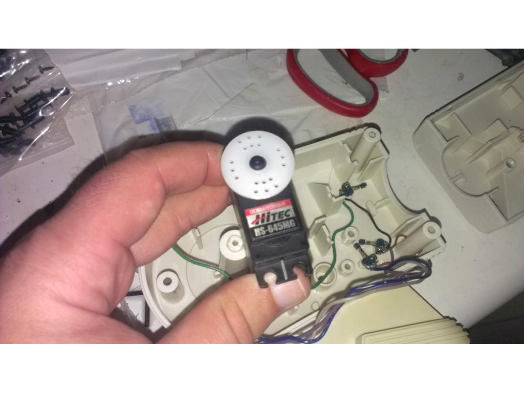
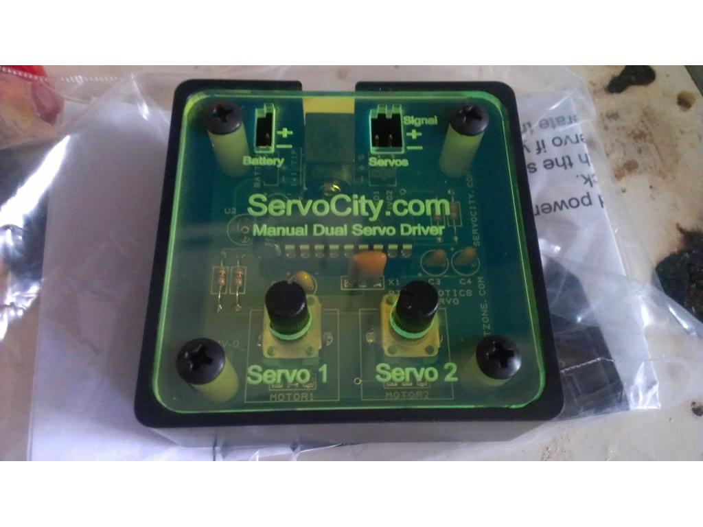
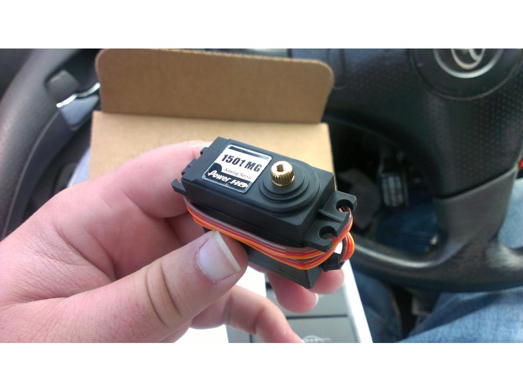
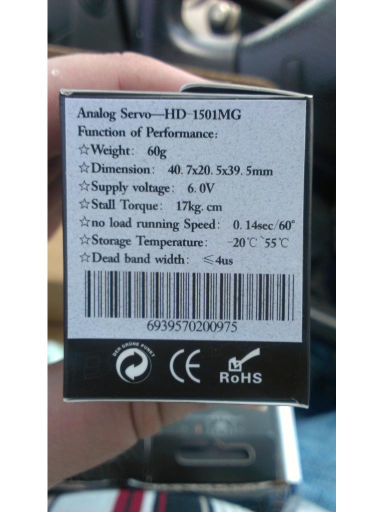
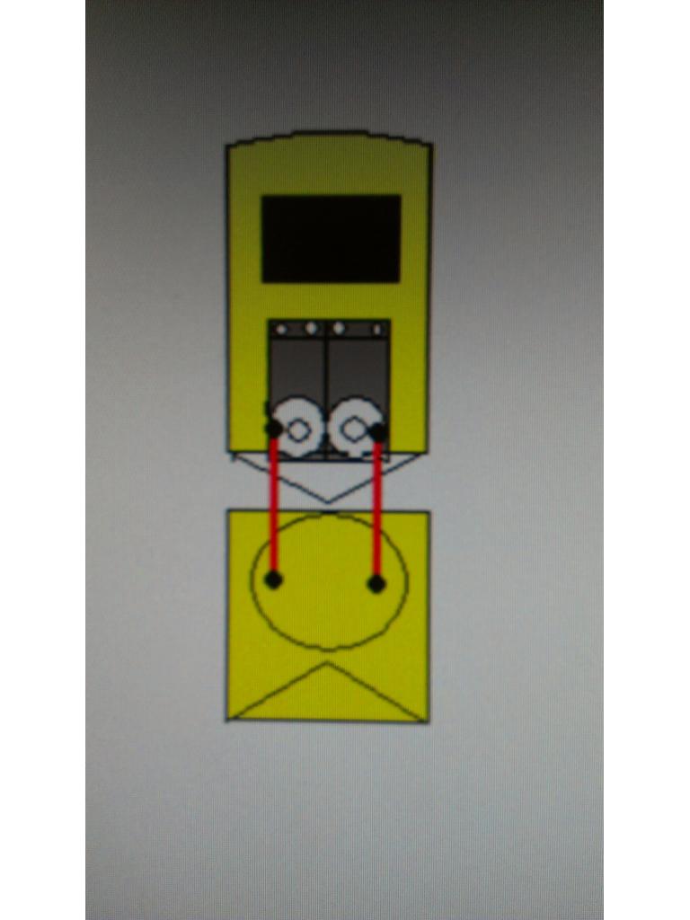
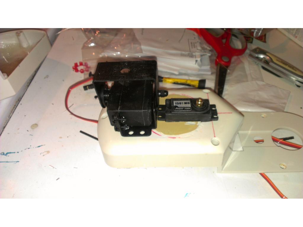
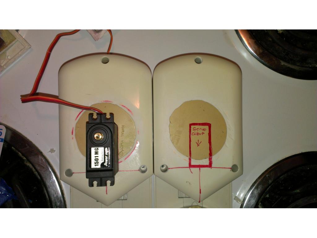
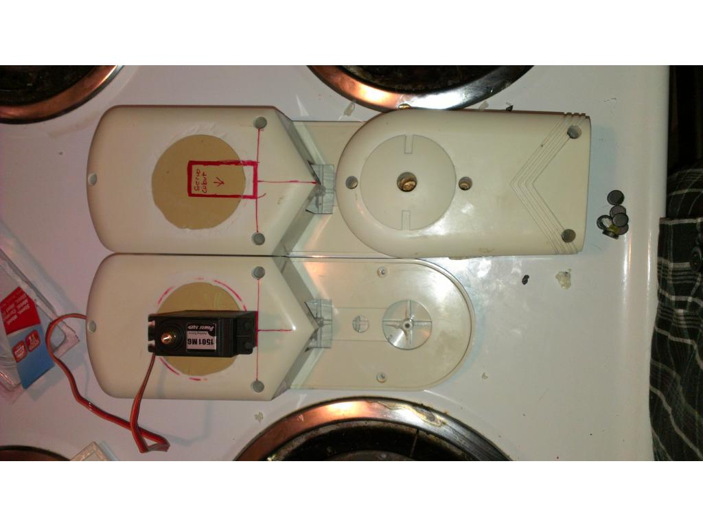
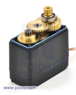
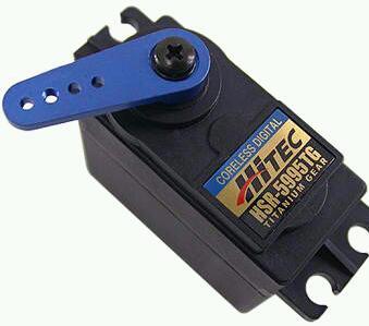
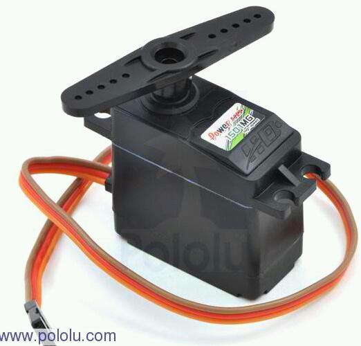
A full Omnibot is a happy Omnibot! Lol. Right now I'm kicking around a idea to use two servos in tandem for arm movements. Mounting two side by side and run a pushrod on.each side of secondary helper servo to main drive servo. Both would share the same signal and ground so they move together this would pracically double the torque the shoulders have. I would like the arms to be able to lift 3 plus pounds so it can hold a wine bottle with no problems.
@jstarne1, Looking great so far! So now that you have a freekin awesome MOBO going into your bot.... a few questions. What do you plan to use for a monitor? What size? I noticed you had a Blue Ray player ready to go but just for planning..and saving power and real estate.....do you need it? Unless you are going with a 42 inch screen or larger... putting up 720p will really be all your eyes will notice for resolution.... and you can easily stream that over wifi (you can probably stream 1080p with the MOBO you have with no issues). That is..unless you actually want to put the disk in the tray to watch a movie, which is kind of a novelty.
You could even put a projector on your bot and have him put up a projection.........or have it so your bot could jack into any HDMI source and get the party started!.....VERY COOL!...anyway, just curious as you have some decent processing power now available for ARC and more if you want. Just was wondering what you were going to do for a screen, or if you are just planning on no screen and remote control? Running XBMC on a built in screen streaming videos while your robot danced would be awesome!
v/r
Kevin
Kevin, every time you talk more money goes flying out of my wallet. Now I am going to need to buy a pico projector dammit
Alan
Lol I have a 7 inch I have contemplated. I figured I would plug in my 42 in LCD through hdmi and when I need it to be mobile I could either remote desktop from the tablet so I see everything vicariously or switch Bluetooth connections to the tablet. I'm not real concerned about having a built in monitor but I'm considering options. Obviously I need somthing small. I thought about using one of those USB powered 5 in LCD monitors and stick it in his chest but I definitely don't want dj to think I'm stealing ideas. And by the time I'm finished I want to be 109 percent sure no one would ever confuse my bot for someone else's . If anyone has monitor ideas I will definitely take the ideas in consideration. Right now I gotta figure out how to make a radar with the sonar module. I've never done it before so anyone who can't point the right direction would be greaaaat. Projector? Wow if I could fit one in Omnibots head after fitting the camera and night time ir led rings .
@kevin yup everything about a bot is novelty lol , I just want to give him as many practical uses as possible. One is autonomous use , sentry , watching bluerays off him , use him as a pc when charging batteries as I don't have any other pc besides my tablet (hard to believe I know lol ) obviously possible plans for autonomous vacuuming in the works. But the reason why I made all connections accessible through the accessories bay is so he can go from desktop to autonomous in seconds. The more practical uses for a creation the more it will get used. Id really love for it to play catch with my dog , she just chases the ball she doesn't care who or what throws it lol.
UPDATE; I recieved the AMD ATHLON 2 x2 2ghzCPU , had bent pins but I carefully corrected them. Tommorow I will bench test everything , maybe load Windows. ( if anyone can hook me up with a copy that would be awesome). I also recieved 2 ,6v batteries uv 645 , the Asus blueray player slim USB powered also came in! Plus 4 more sqaure ft of dynamat came.
PICO projector? Anyone have links , costs? Specs?
Anyone point me to right article for making a radar setup with sonar sensor?
Thanks guys all support and suggestions greatly appreciated , I'm just trying to mod the greatest omnibot 2000 to date , and I'm confident with everyone's help I will!
Here is the link to the PING radar tutorial: https://synthiam.com/Tutorials/Hardware.aspx?id=3
Note: since this was recorded DJ made a change to the ping calibration and it no longer measures in inches. Each increment is ~0.27 inches (~70 inch maximum range / 255 increments).
Pico projectors: http://www.tigerdirect.com/applications/SearchTools/search.asp?keywords=pico+projector
These are last year's models and stock over-runs for decent pricing (as these things go). None of the Pico projectors has had great reviews yet, although they have been improving every year since they came out about 3 years ago. At this time, I would just buy the cheapest available because the difference between the best and the worst is not significant.
Alan
@alan thanks man. Ok guys I have a idea to add some movement to a omnibot. A turning waist ! I believe I could do it with a couple heavy duty metal gear servos and a ball bearing swivle plate used in furniture. I love the flexability of what Muppets thought Omnibot should have been.....besides that he's all yellow and dirty lol. And yellow eyes.
I particularly like the 5" floppy drive in his chest hahaha
@bret......ill just go.with a dvd/blueray in the same spot.... I'll use that more . I haven't.seen a floppy like that in ten years in person.
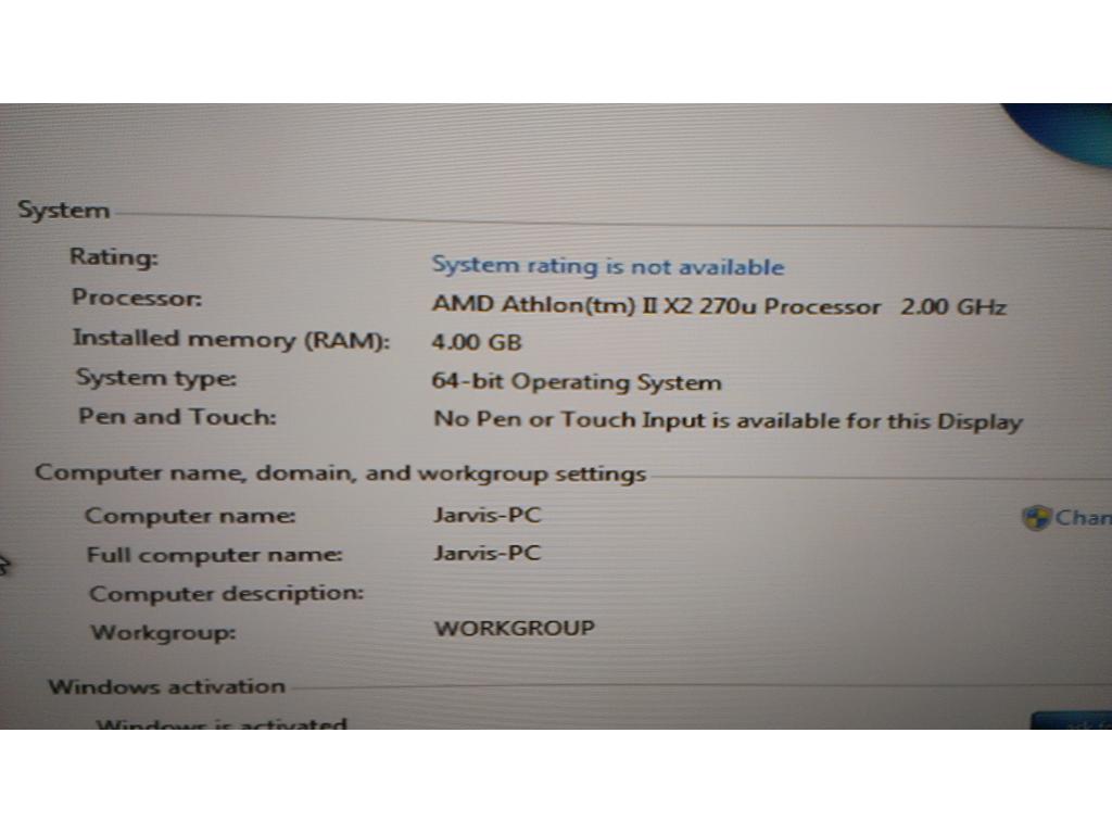
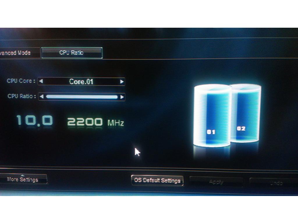
@kevin good news I researched to AMD II x2 270u is the exact same core as the 3.4 GHz CPU the multiplier is 17 vs 10th. This board can actively unlock cores and memory unlock so I should be able to clock from 2ghz to 3.4 at anytime. Wattage draw is 65 watts. My 12v dc power supply is rated at 160 so maxing out this CPU I'm still good on power.
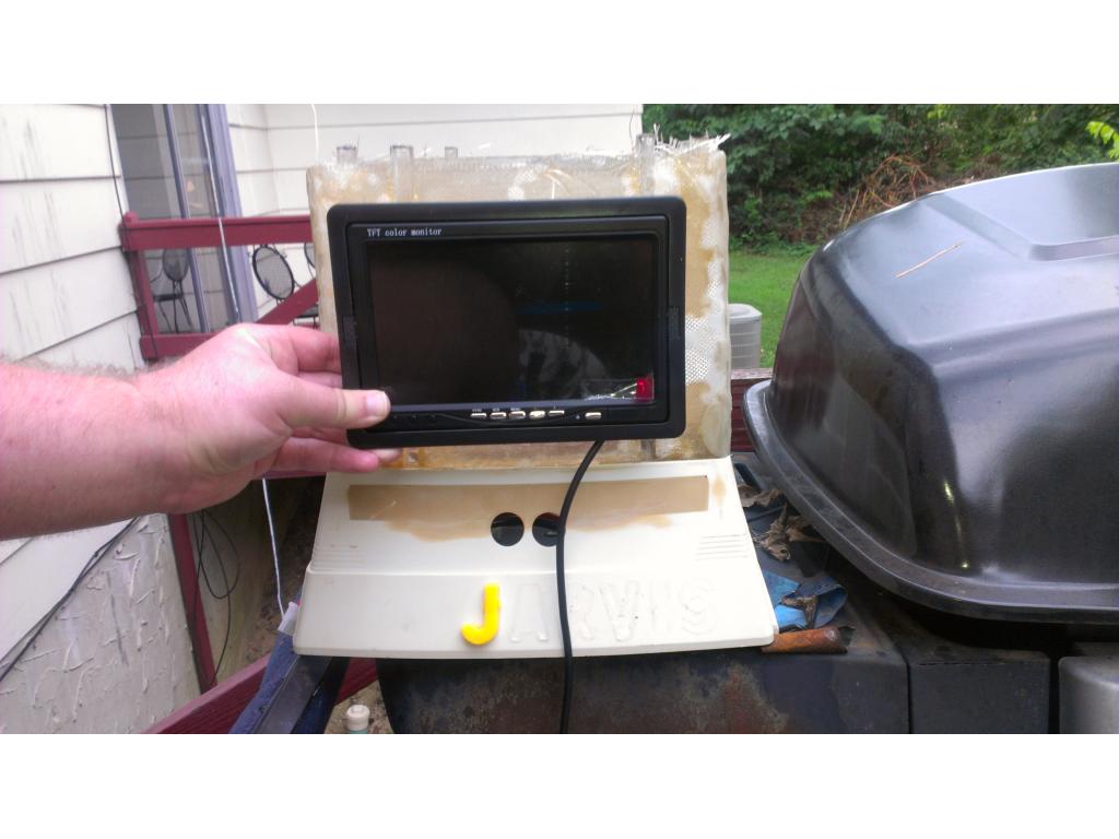
I took your advice and found a 4.3in LCD monitor that powers on with 12v , that means it powers on with the robot. IT has no buttons or logos but is from USA and has 3 yr warranty. It's only 28 bucks shipped too
http://www.ebay.com/itm/4-3-TFT-LCD-Digital-Monitor-Vehicle-Parking-Reverse-Camera-NTSC-PAL-12V-/130640469901?pt=LH_DefaultDomain_0&hash=item1e6ac75f8d
I have lots to fit in his chest , so far I have a5.25" bay 5 zone LCD temp and fan controller from cooler master (this keeps fans spinning at.minimum unless temps go up. Saves battery!
Also.in his chest goes a LCD display for battery status , power supply voltage from battery , total wattage usage , amps being drawn and battery temprature during charging/ operation.
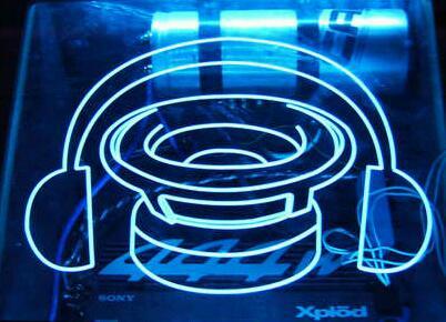
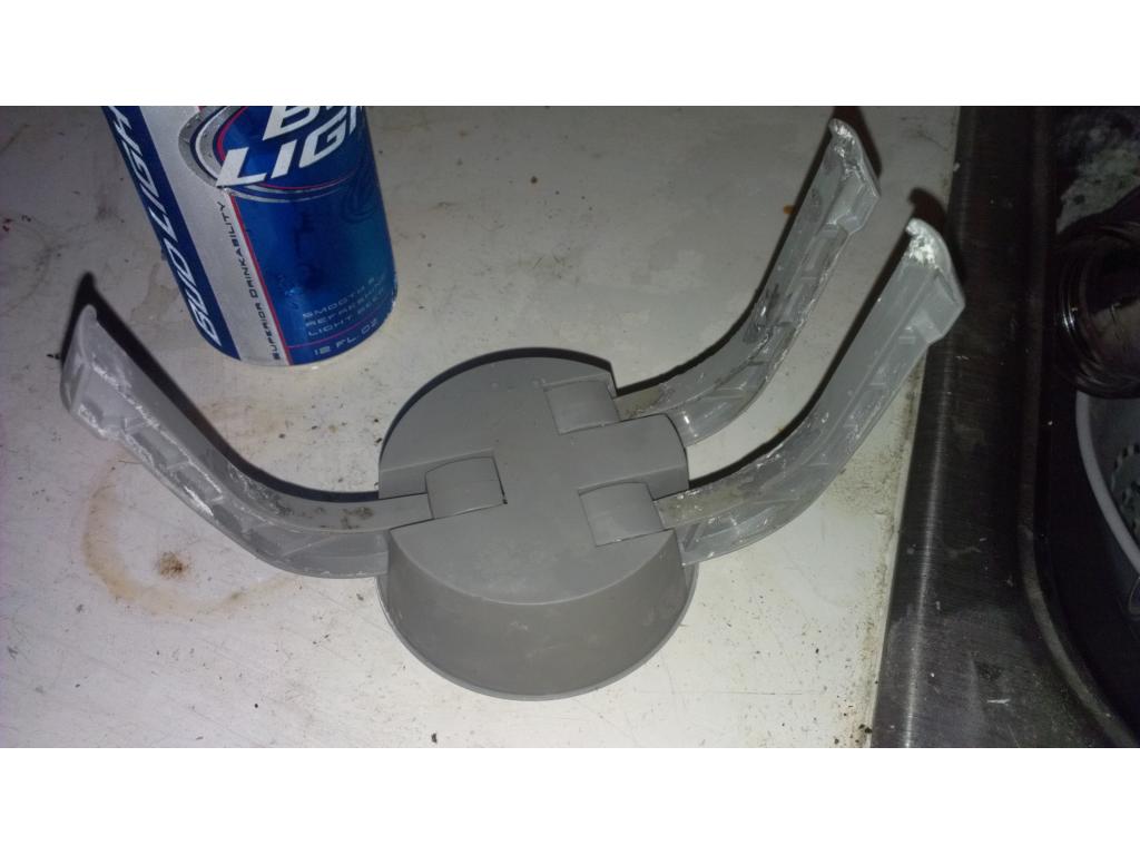
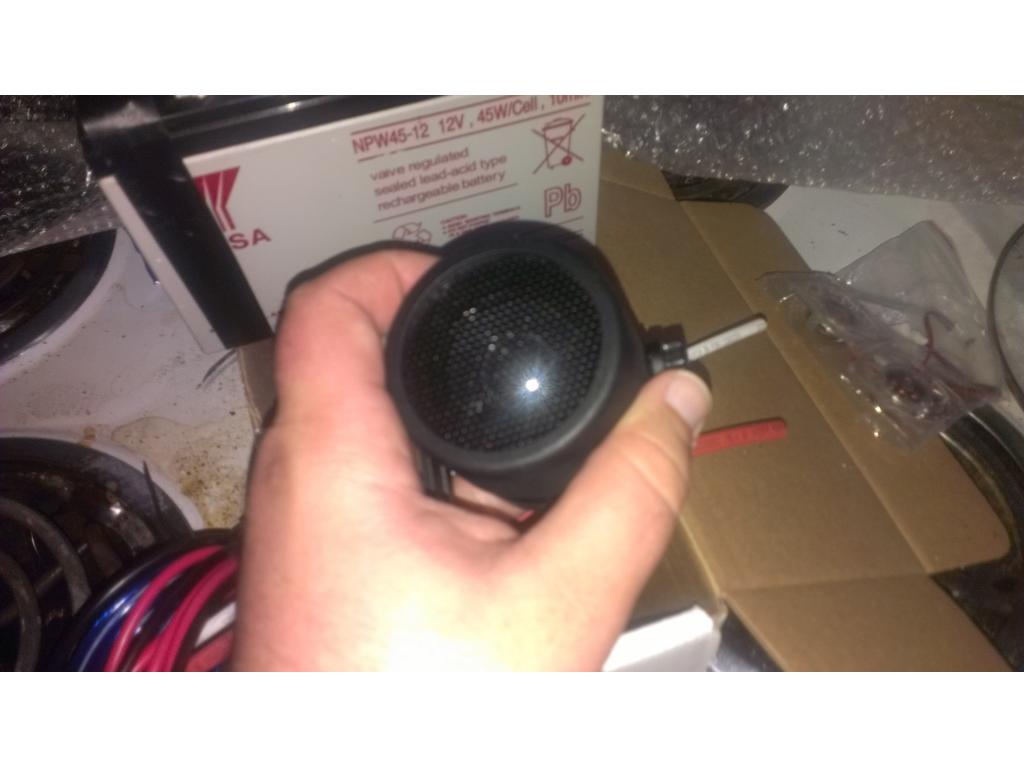
Check this out for omnibots claw center. http://www.ebay.com/itm/Belt-Clip-On-Plasma-Sensor-Disk-Luminglas-Light-Circle-/180639982470?pt=LH_DefaultDomain_0&var=&hash=item6fc39573ab
I am going to put a 6" version in the chest of my big bot. This could even be cool as the eyes, and it responds to sound.
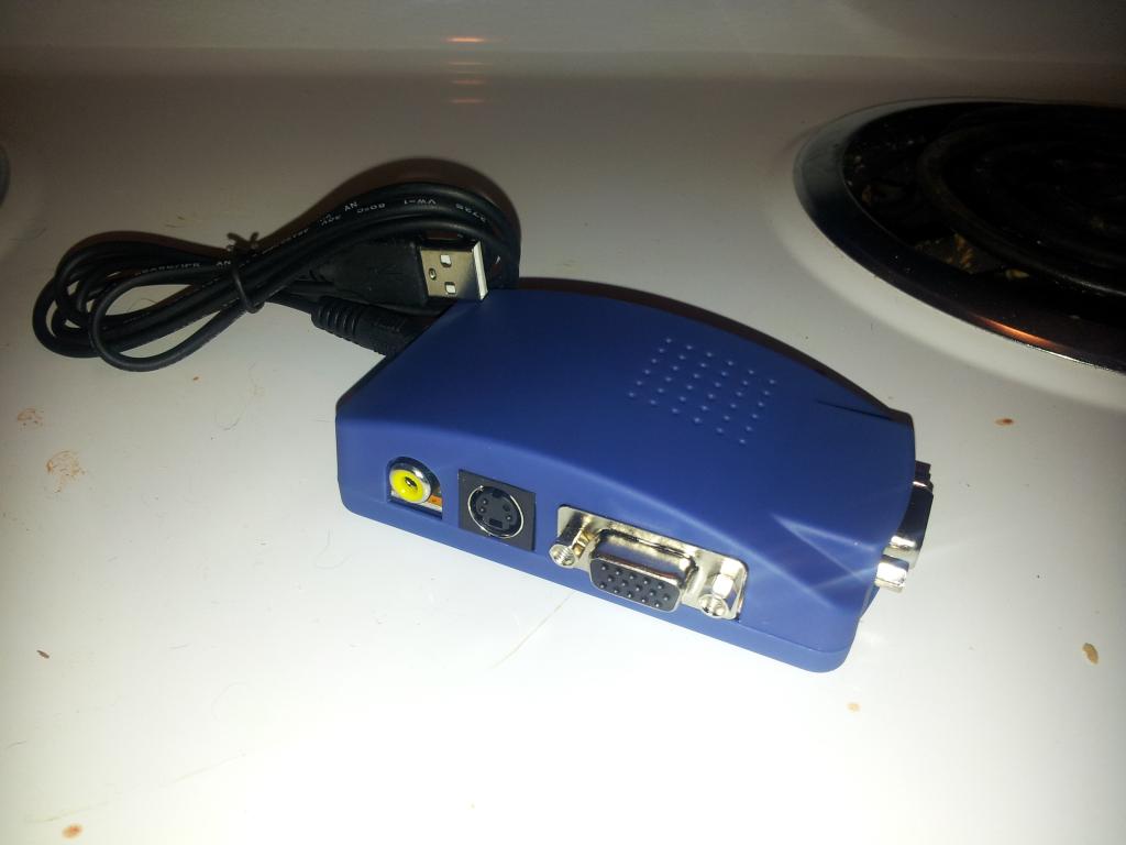
@jstarne1, Wow you are moving out on the gear! Glad you are going for a screen. I hope I am not bearing bad news, but it looks like that screen may not work directly with your MOBO. Your MOBO has DVI and HDMI out and the screen on ebay is NTSC/PAL which will no work without conversion. Converters, while not super expensive, will take room and power... and you are going to loose resolution with that too. If you already bought it, you can still use it....may be a bit tough to fit everything in your bot. I hope this is not too bad of news for you. I will see if I can find some DVI screens which would absolutely rock at a decent price.......
@Bret That circle thing is trippin'. I think i just found a centerpiece for Legion...if you don't mind me stealing your idea shamelessly!
v/r
Kevin
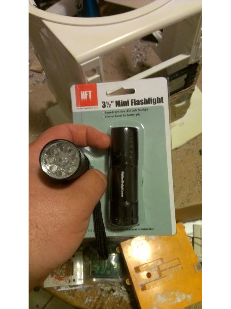
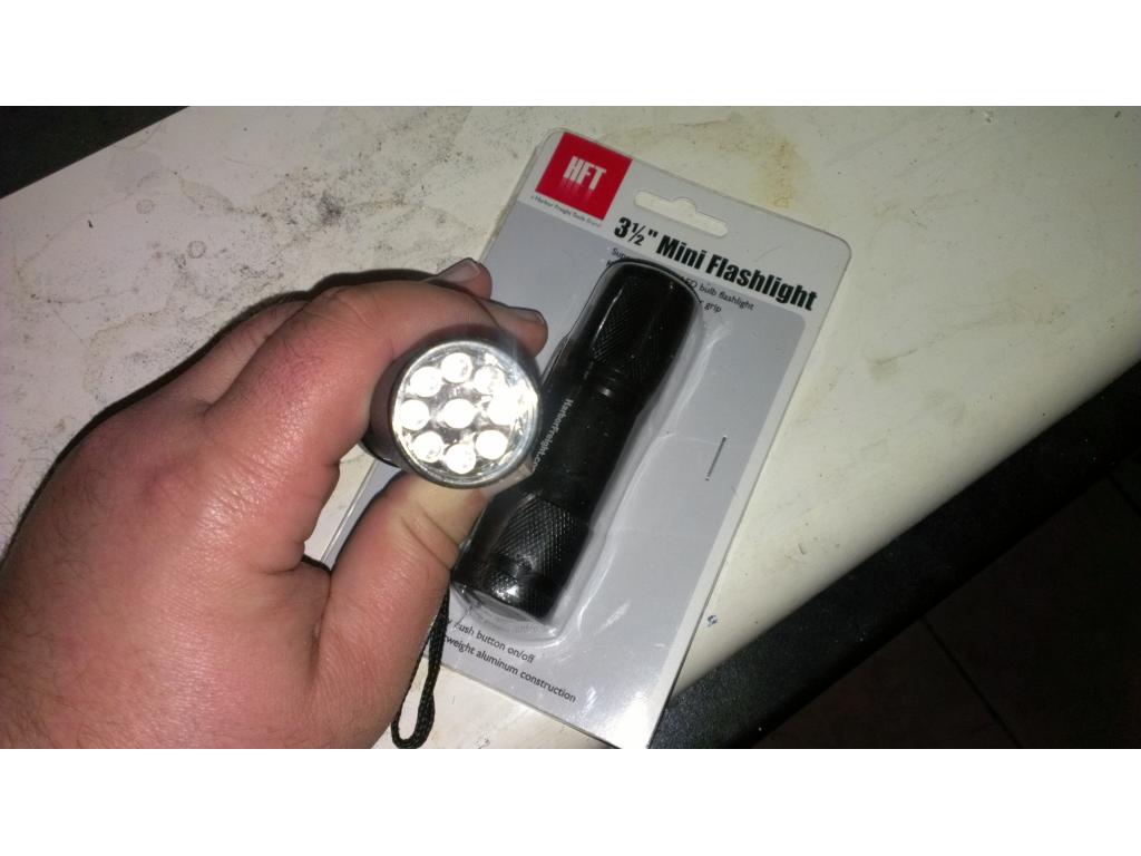
Ok I've descided the vacuum unit will be a seperate unit that attaches to the back , but power head built in is what I'm thinking. That way it can be removed easily anytime. Just a thought there. Also I believe ill do eyes with either el film behind some plexi or just frosted Plexiglas side lit with LEDs. I was thinking " what would Tony Starks personal robot look like , his personal flashlight and screw holder , what a bot might look like rolling around his shop.
Go for it Kevin, I think it will fit quite nicely in Legion's chest. They also have them in rainbow colors and other single colors. But I liked the blue and the green ones best.
@kevin board has a "tv out" with is regular RCA video connection.... It's standard definition but on a 4 inch screen no one cares. . This really is a perfect board to do this project with ...
whew....good good! It looked like SPDIF coaxial audio ..... in the pic above or was that your old board? Whats the model of your new one........I am taking notes...
@kevin. Ok I lied , its not a video out ,wooops! Not the end of the world though because I can grab a video card that has a tv out or somthing else that will produce the standard video signal. From what I understand there's a dvi to composite adapter for 30 t0 40 , I think I would rather invest that money into a suitable video card. Anyways its cool everything's been super smooth in this project so I'm happy !
I was able to salvage a lefty motorized arm from another Omnibot 2000! Woohoo with two potential motorized arms now I'm more concerned about getting good head movements. I need left/right turning , side to side tilting , and looking up and down. The tilting to the side with the head would be a great reflex after recieving a voice command , or if the bot didn't recognise a command as if he's thinking about it. Any ideas or info for setting up neck movements let me know !
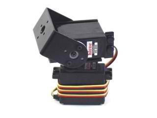
you need a mount like Helicopter .LOL 3 servos,(L to R, F to B, Spin) I'm sure you can do it .
@ww321r. That sounds like a option minus the head spinning. Maybe like a ball joint with pushrods going down to neck where the three servos will be ! If anyone finds a specific piece of hardware please link me ! Thankyou
Spin meant ,left /right movement. You could make a gimbal I'm sure. It would allow you to tilt the head at any angle . Like this You would attach the servos at 90% from each other centered on the pivot point. Should make it very lifelike J.W.
gimbal
J.W.
gimbal
Or like this idea
http://www.goodluckbuy.com/xaircraft-cm130-tps-pan-tilt-camera-mount-with-3-servos.html
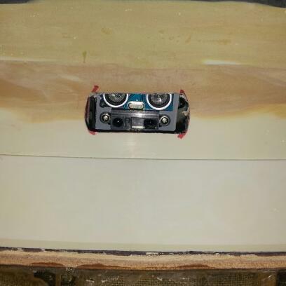
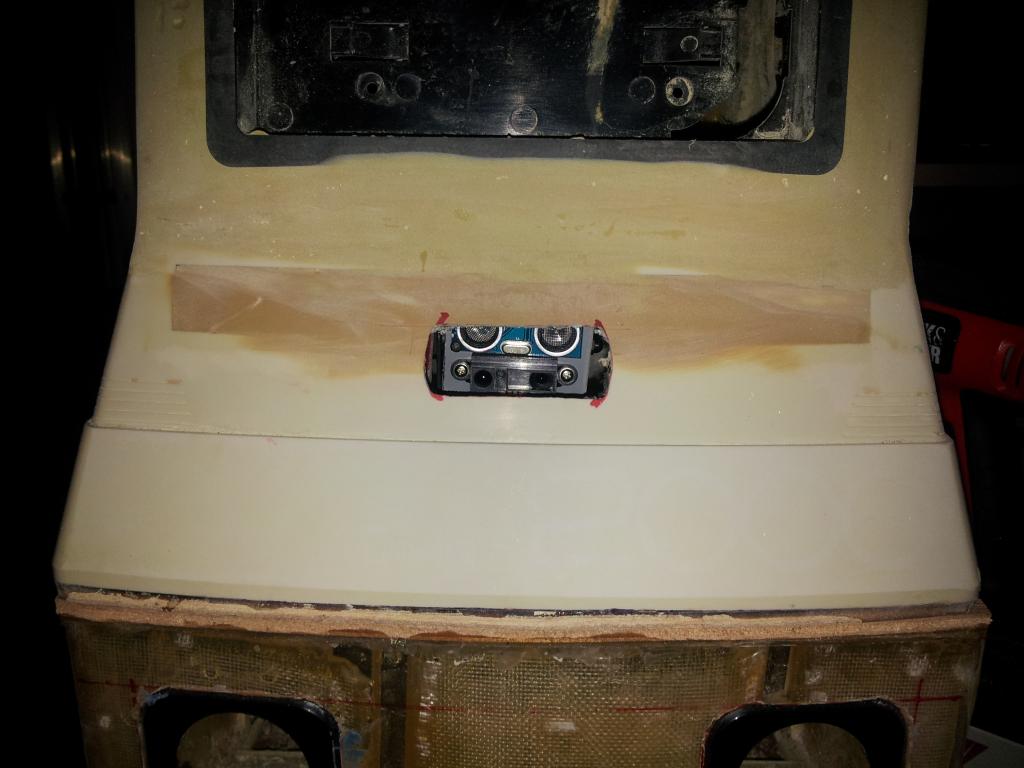
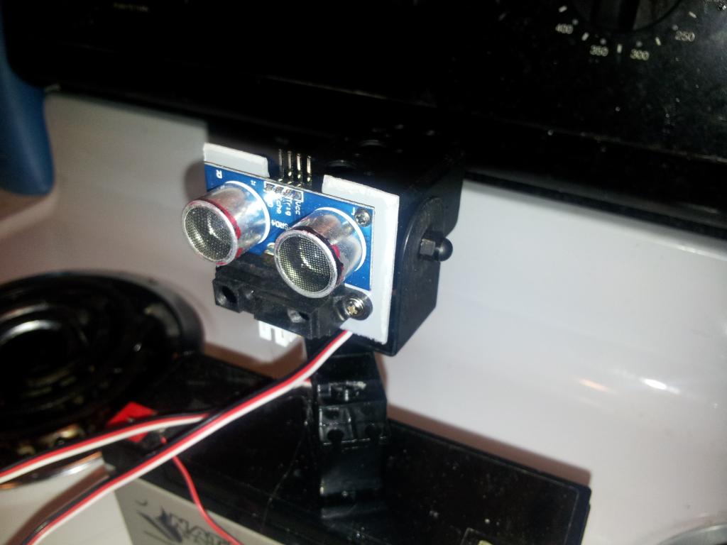
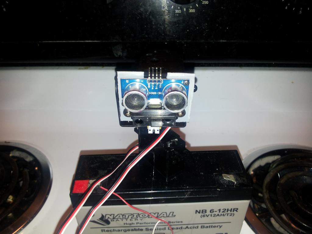
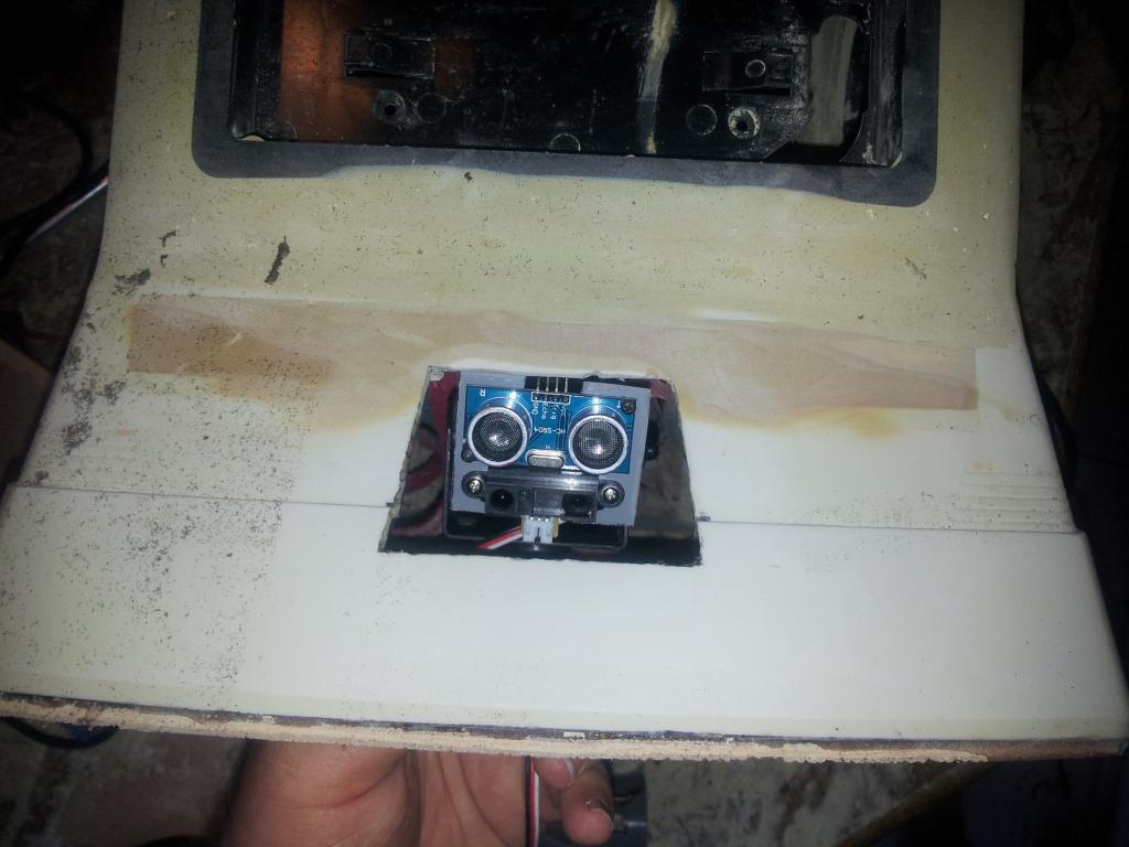
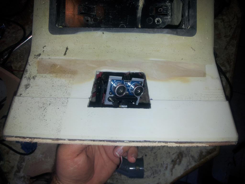
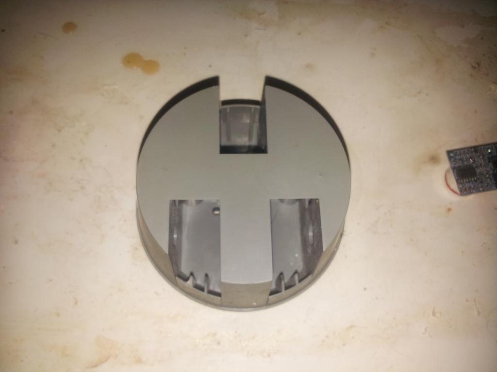
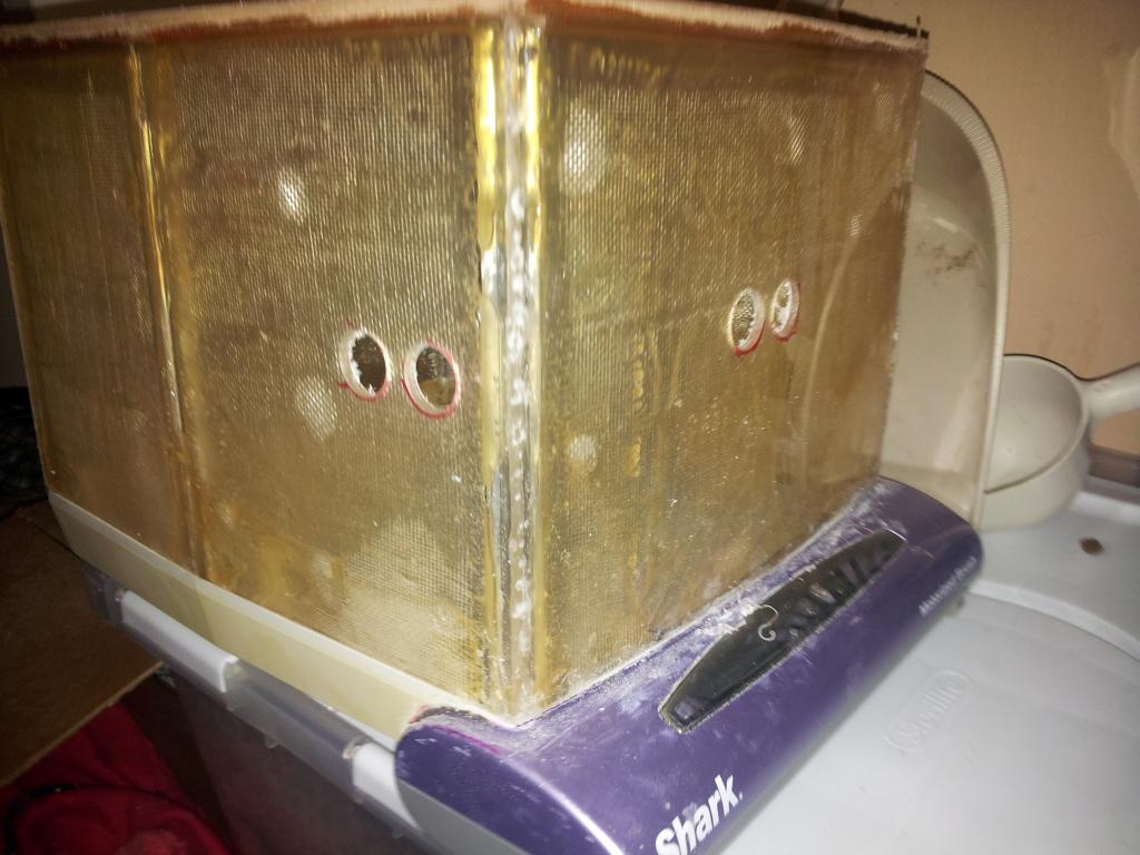
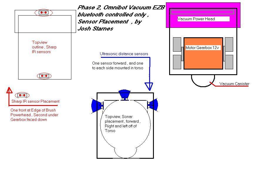
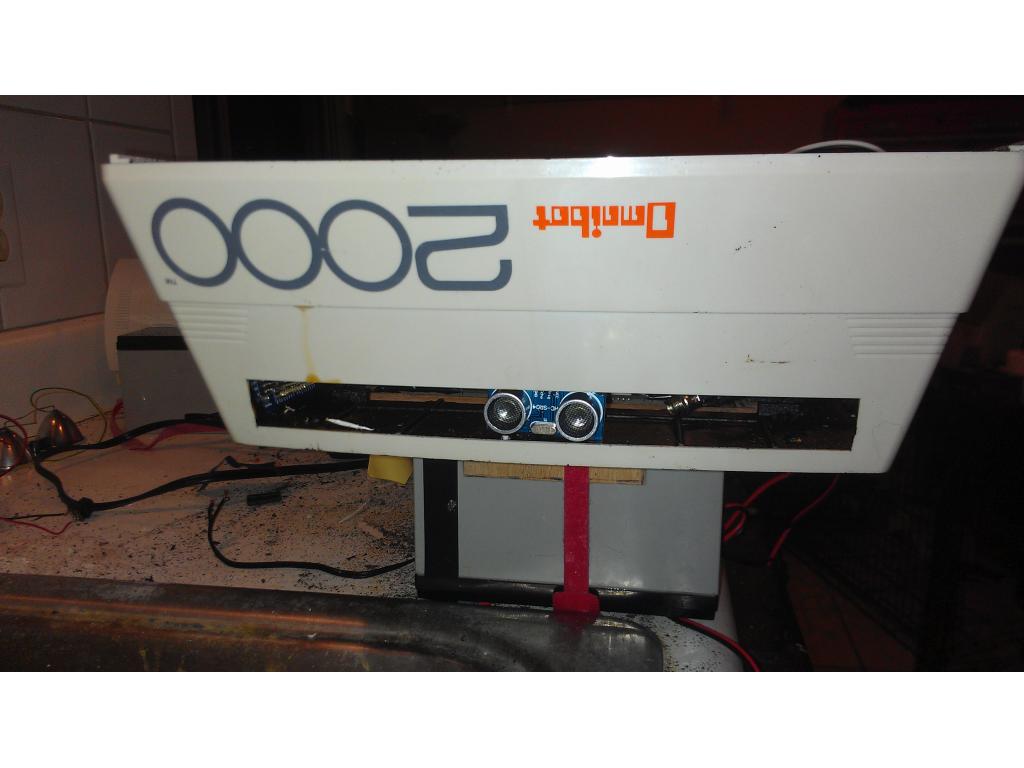
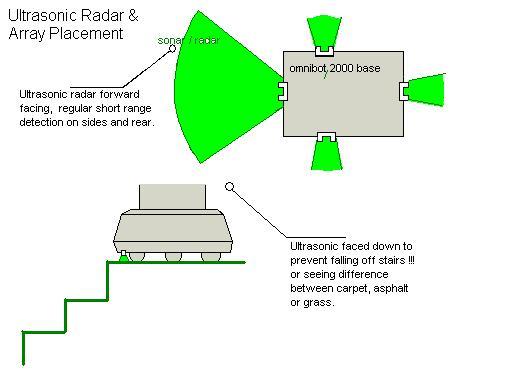
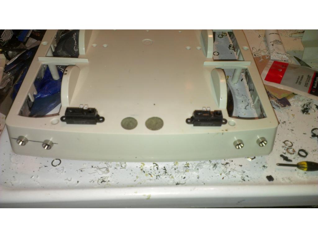
Here is my proposed rangefinder placing. The front is radar , sides are still on the drawing board but the idea is that the could measure a couple inches off the wall to make sure Omnibot is not scraping when vacuuming. Rear is ONLY used when backing up for object avoidance. I was thinking of one sensor faced down on the front edge to avoid drop offs and stairs. I have thought of a sensor for edge avoidance on the back too. I have 3 sensors on the way and one was included in the kit. Any better ideas?? Feedback?
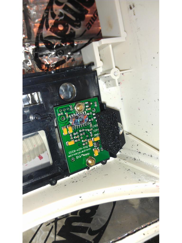
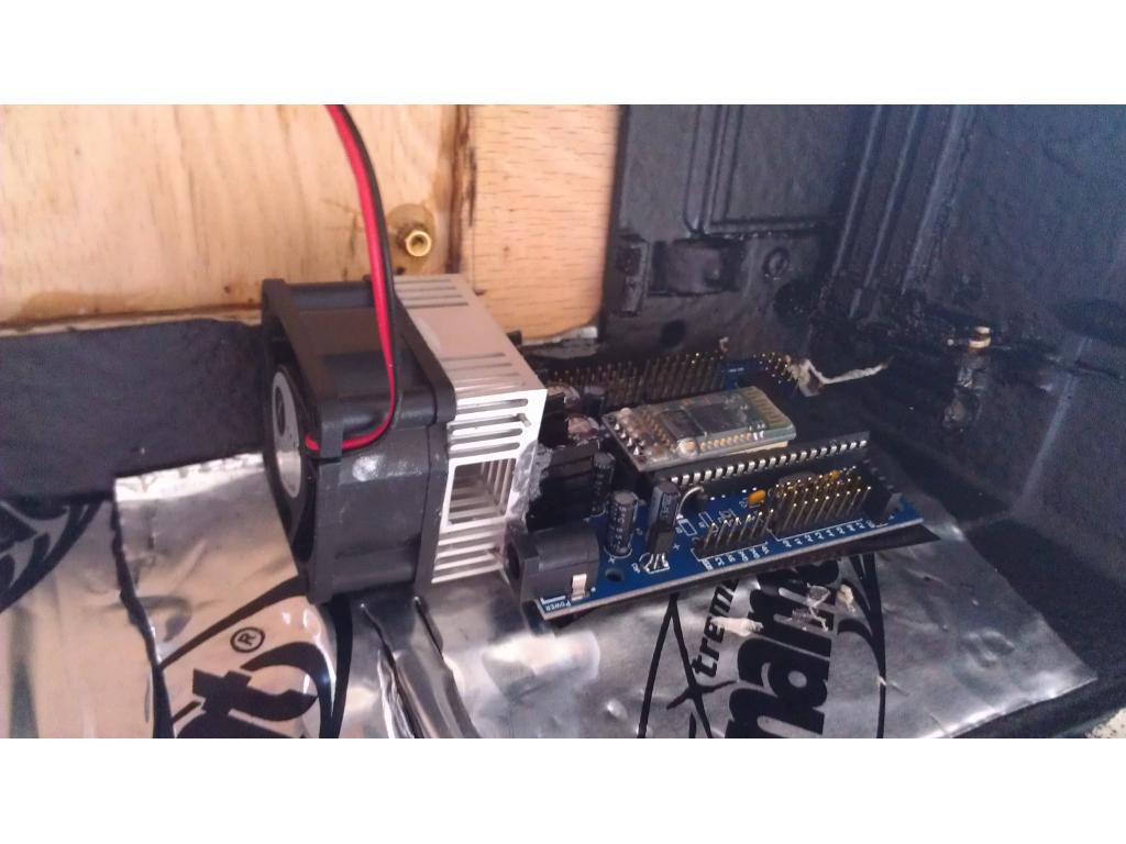
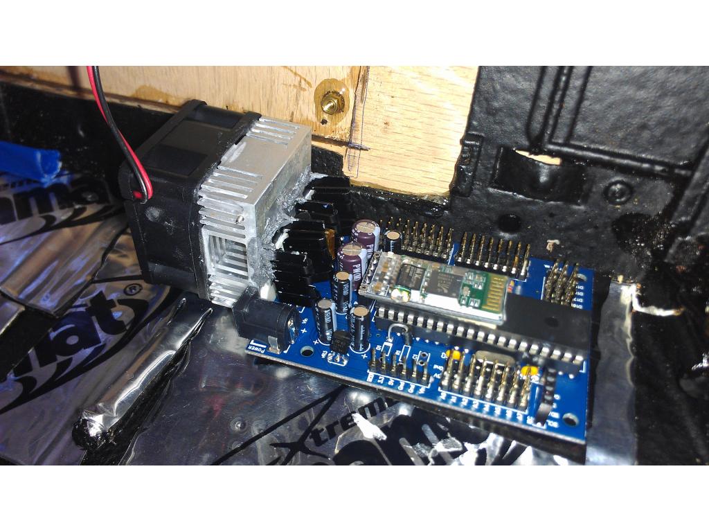
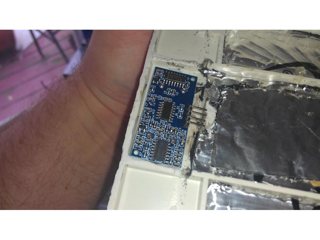
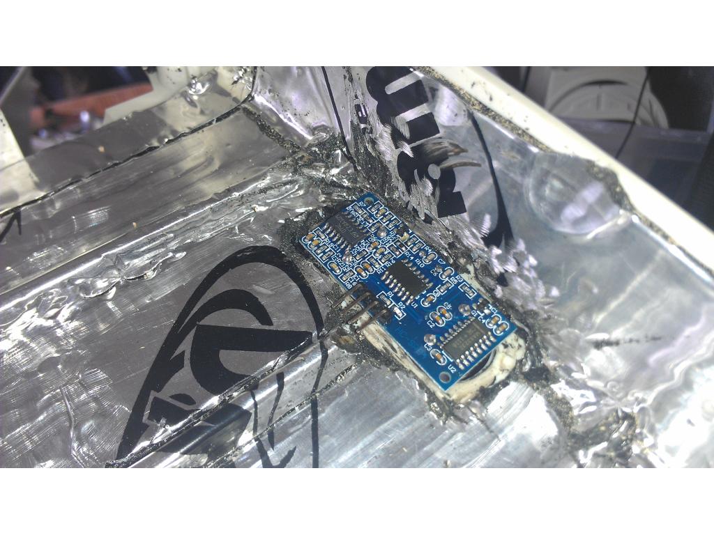
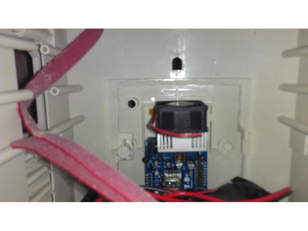
Ok I used a new 40mm x 40mm x20mm fan and VGA heatsink to add some additional cooling. The fan has a few drops of super glue attaching it to the heatsink. The heatsink has arctic silver paste on it where the voltage regulators touch it. At the bottom where it meets the board its just 3m double sided tape. I did cover the outside edge of the blade fuse with electrical tape to prevent any paste run from touching anything other than the heatsinks.
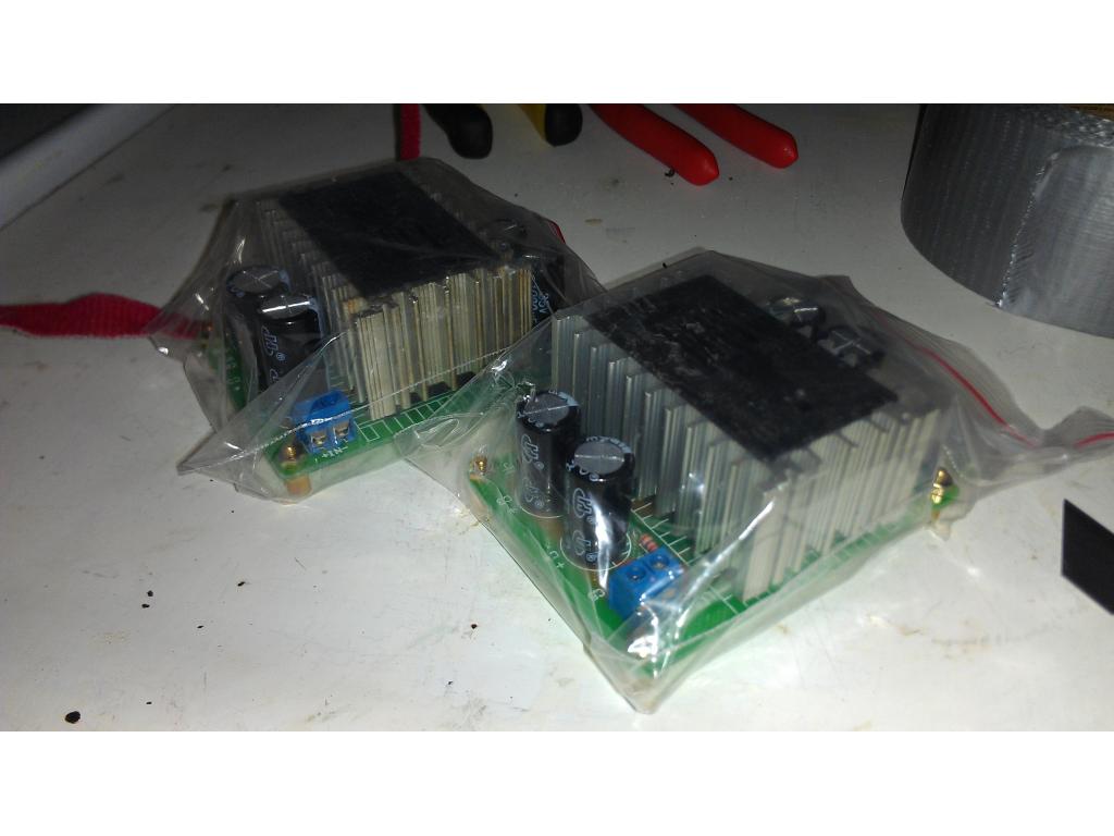
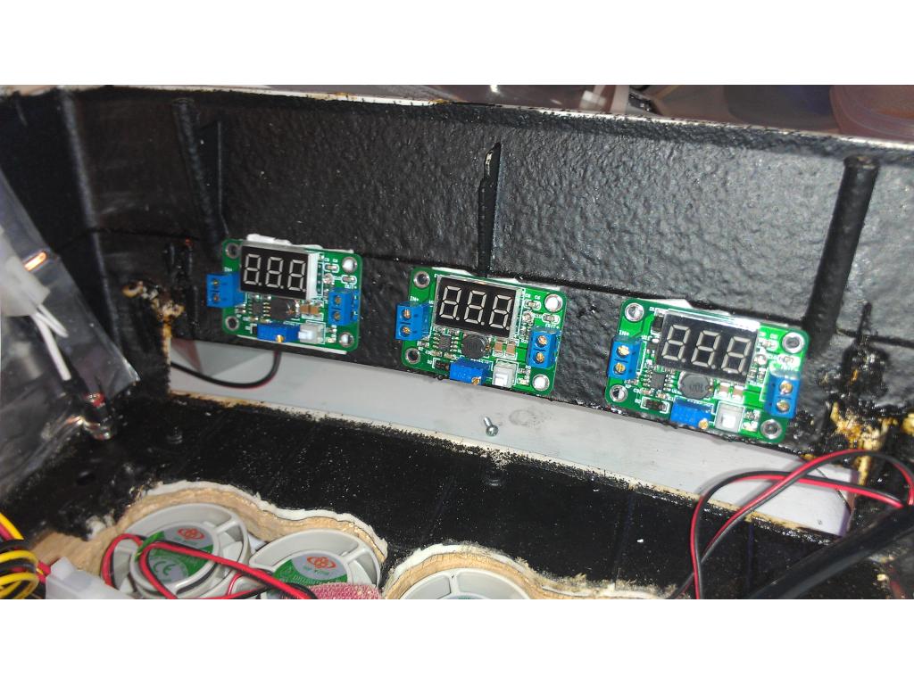
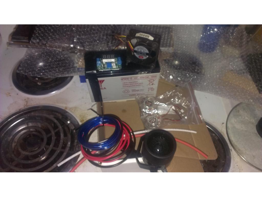
Update: card reader / blue led fan controller came in! Also the LCD voltage,amp, watts and temp meter for power supply monitoring . Plus the fans and Blueray player came in !!! Lastly the voltage step down power supplies came in so I can power ezb from 12v battery , the motors at 6v and seperate power supply for High Torque servos as well Wow
Wow
All I'm waiting on now is my h bridge motor controller from dj which is in the mail.
Now I just got to figure out where I'm going to mount these things. I can do cutting on chest and cut edges of controller off and put it in the chest......OR I noticed the drawer in the back of omnibot 2000 is the same width as a standard cd drive bay. This is crazy that I was thinking of putting everything in the chest and this is perfect size. Downside obviously is putting drives in the back is less accessible. Any suggestions guys??
That's some serious fan!! I think this bot combo is gonna be aweeeeeesome
Lol yea but moves 6 cu ft per minute and is very quiet. Low current draw for the airflow too , given the presence of other things generating heat , like CPU , power supply , and other stuff I want to make sure this little guy has excellent cooling.
@DJ thanks ! I really hope everyone likes it , I will make improvments overtime but I really appreciate your feedback dj.
hello ,
found this and think its useable for you
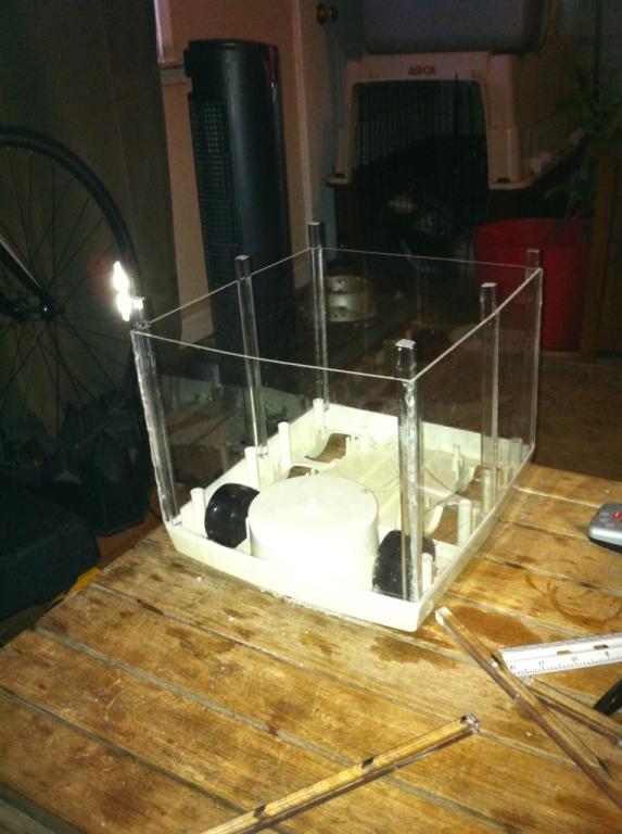
http://www.instructables.com/id/Tiny-Wanderer-A-Table-Top-Robot/
bot can't fall of the table
greetings
helmut
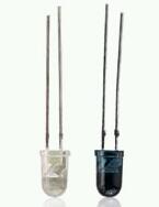
Ok so your thoughts are one IR led and Reciever on each corner pointed down. Using these parts : 2 -- 940nm IR LED (ex. LTE4206 --available from BG Micro) 2 -- 940nm IR photo transistor (ex. LTE4206E -- available from BG Micro)
note: Radio Shack part 276-0142 - IR Emitter and Detector will work for the the parts above
@ jstarn1 and helmuteke - I like that idea. Simple and reliable.
I'll consider it , right now I have 3 ultrasonic sr04 coming. , maybe place them the exact same.way.just.using a.different type of sensor? One in front of each wheel just like this little bot in the videos that way it works on dark or shiny floors and glass.
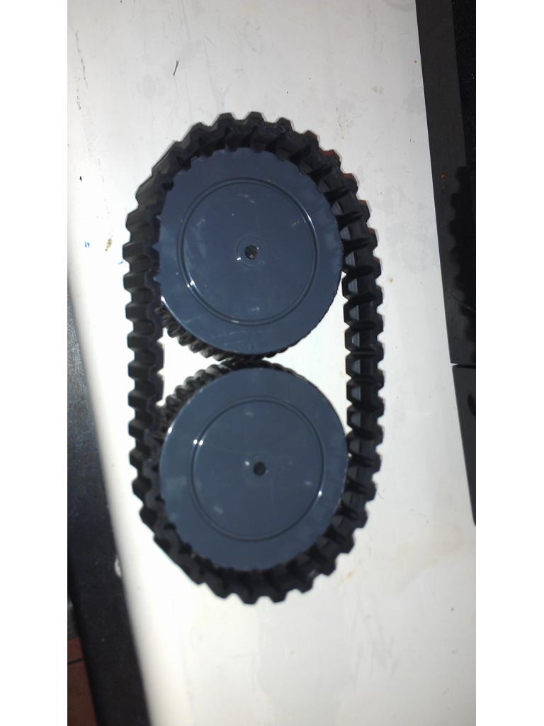
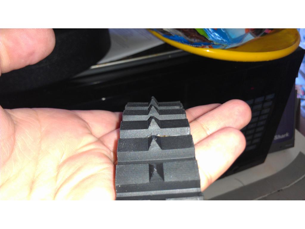
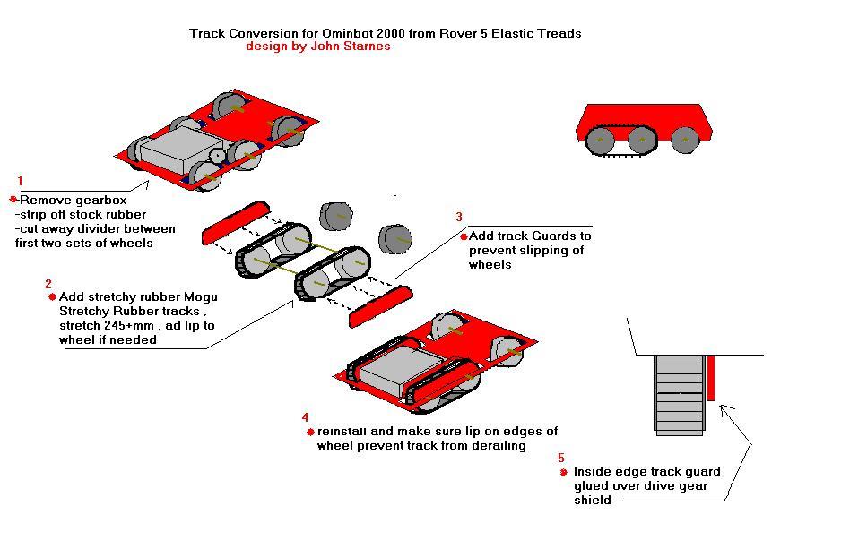
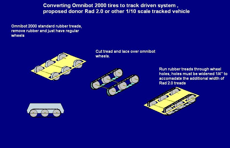
Idea here is to widen the slots for the wheels and use wheels with no tread to lay track over. If your tracks have a guide grove u can modify your omnibots stock wheel for it. Rad only has a few teeth every couple inches so knotching shouldn't be too difficult. Any ideas? This way u can incorporate rad 2.0 tracks to run on a near silent drive train and everything will match up perfect , thoughts?
@jstarne1,
Concept for tracks is good but making it look and work well may be difficult. I would like to do my own track system but keep running into difficulties that unless you go with matched gears/treads you are going to have tracks falling off/slipping and all sorts of stuff.
about the IR sensors. I you look through some of the threads they tend to be a bit less reliable over the sonic sensors...either would be worth a try. IR sensors can get wacky sometimes with various light sources causing interference (like a candle for instance will reek havoc on an ir sensor....backlights on flat panel TVs and also CFL lights)...not that that would apply with them mounted on the bottom side of your bot though.
v/r
Kevin
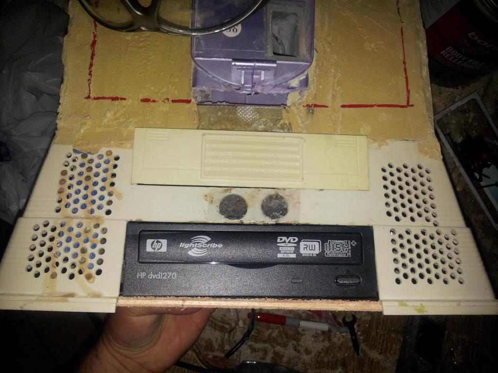
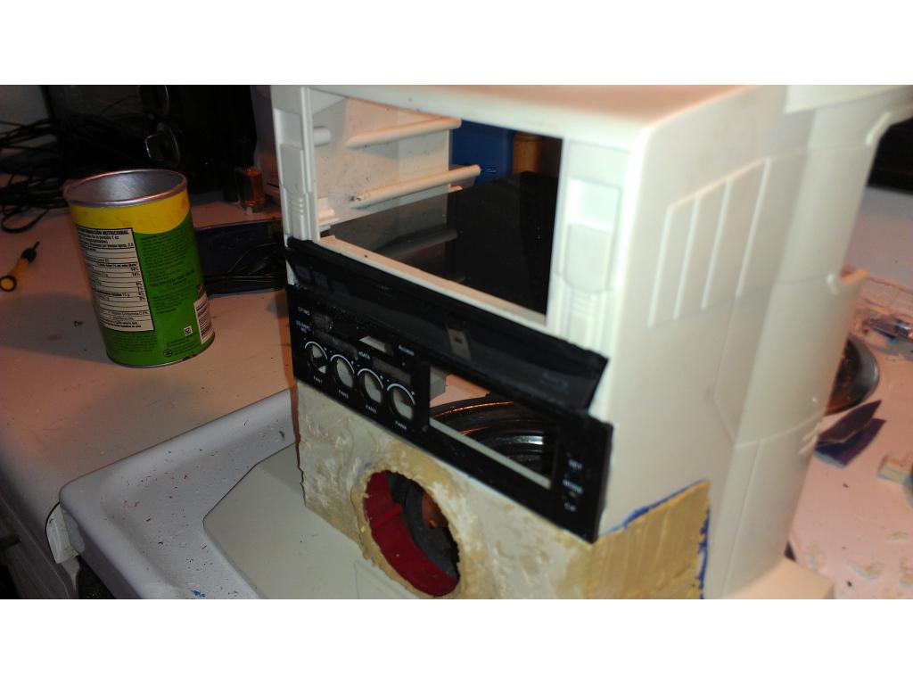
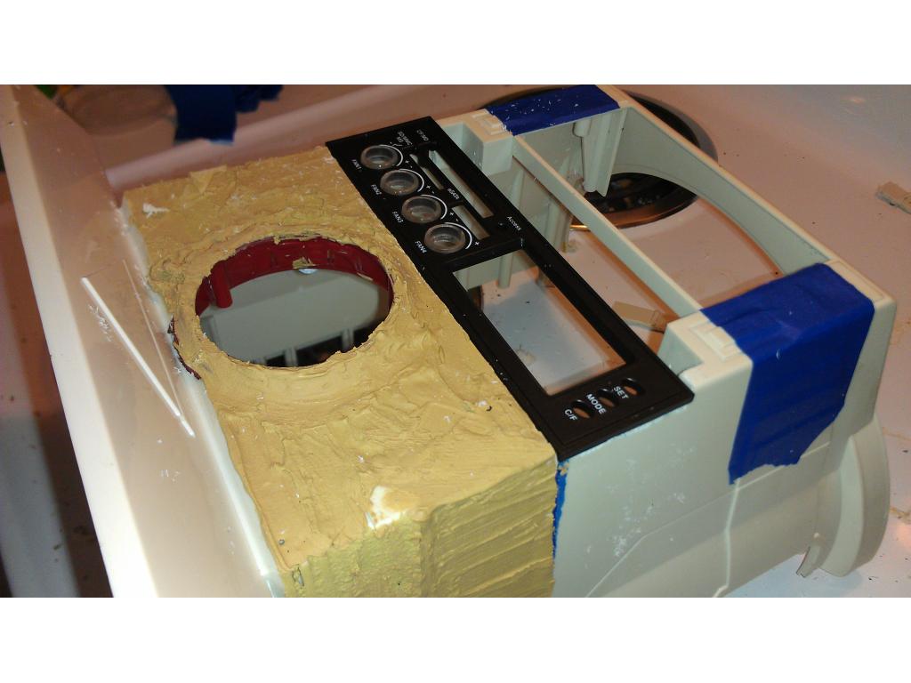
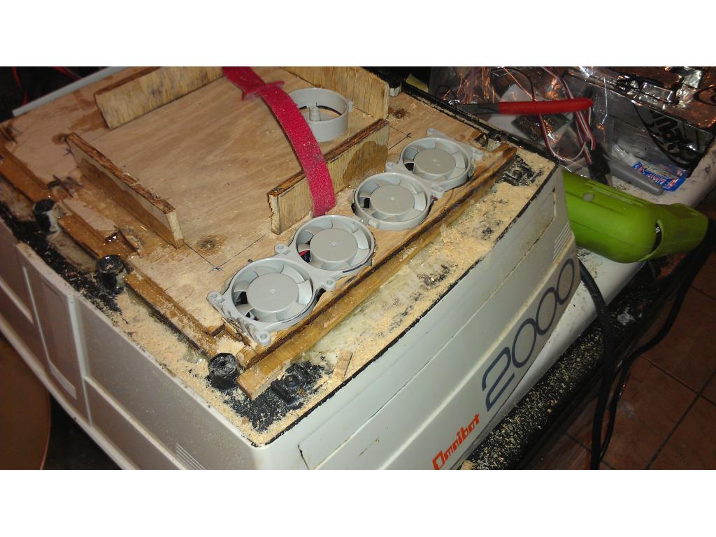
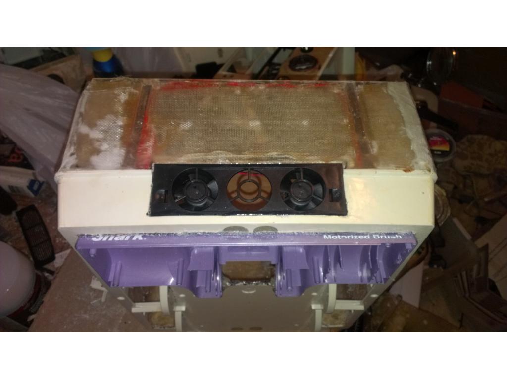
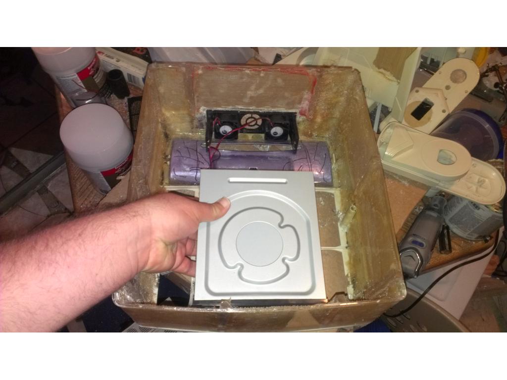
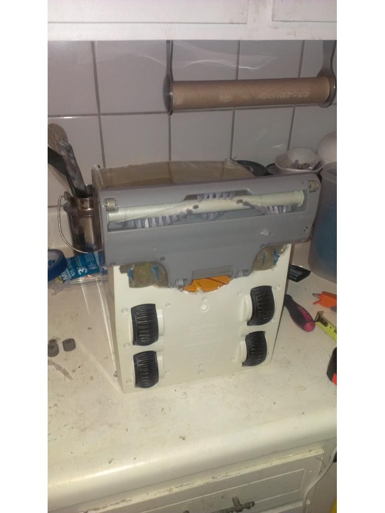
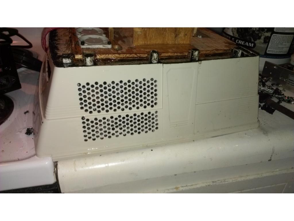
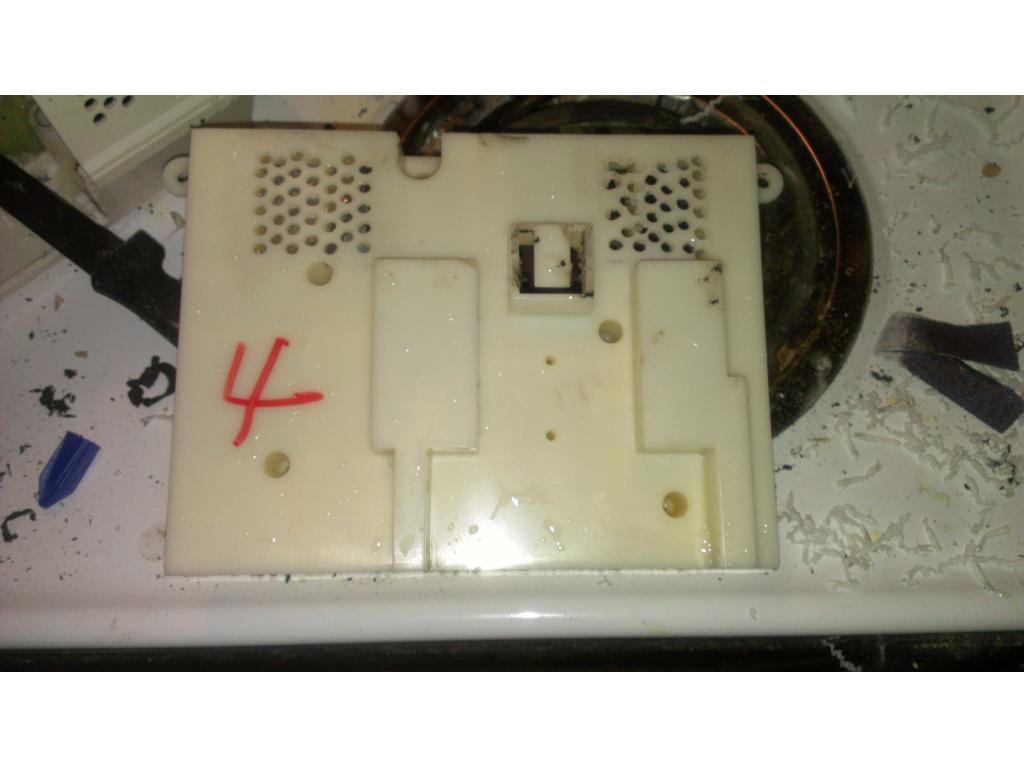
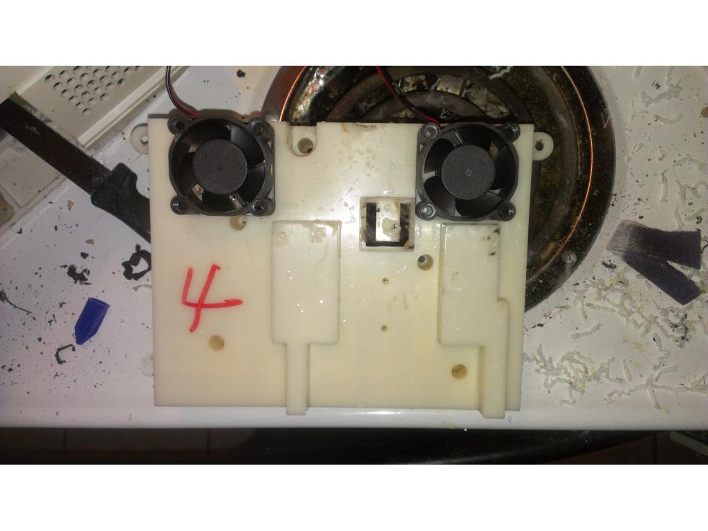
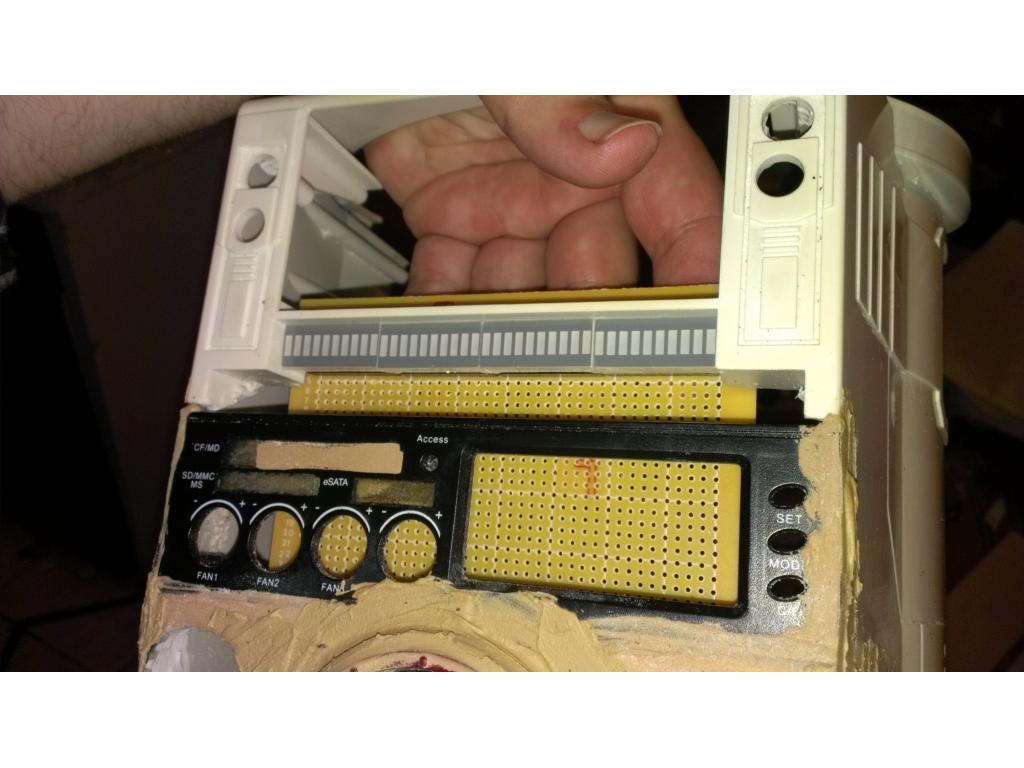
I cut holes to flushmount 4 40mm fans to pump air into the base. I cut up HDD bay cooling fans for this. Playing around with mounting positions I'm considering this location. I've descided to retain the original switch and LCD panel. I'm just going to put my own spin on it. . Dvd drive fits at home in drawer hole. I plan on cutting the hole down to make it .5 inch taller opening that way I have two full 5.250gig pc bays ! One bay I'm inserting a 5.25 bay triple 40mm fan probably as a exhuast blowing outward. The h bridge , ezb , hard drive , and maybe even motors will have individual cooling fans so all I need to do is keep 20-30 cu ft a min of air flowing through the torso and out the base.
that is looking totally SICK...looks like you got the cooling down for sure! well done jstarne1!
Nice! You are blowing me away Dude!
@brett , then get back in the workshop! Lol I am excited to see your bot running around! I just now got the H-bridge from Dj. Once it has a fan on it and maybe a heatsink if I have one small enough I can start the tedious task of plugging everything up. So far I'm thinking of having the ezb and motor controller in the torso so I have fast access to them through the back door. . Hopefully this h bridge from dj is enough to lug around my bot. I'm sure it will draw 1-1.5 amps a channel. I have some fiberglassing to do to reinforce the plastic around the axles and wheels as they are supporting twice the original weight and ofcourse being 27 years old doesn't help lol I have voltage stepdown transformers. 3 adjustable ones. I was going to convert my 12v battery voltage to 6 volts for ezb , 6 volts for motors and 6v for servos I believe. I did have an alternative idea.... A battery configuration that supports both voltages....hmm ill post a picture.
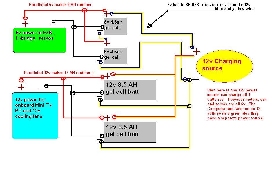
Ok the term paralleled means all positives are connected together and all negatives connected from batteries of the same voltage. Paralleled batteries of the same voltage adds their Amp Hour capacity at that voltage.
The term series is where batteries are wired positive to the next batteries negative and positive to another negative. This is commonly called a daisy chain. Series two 6v batteries together and you will have 12v at the same Amp Hour rating.
Ok here's the idea- ezb, motor controller and servos need 6v everything else is 12v. I want to be able to charge them from a home base eventually but for right now it would be through the DC charge port already in omnibot back. This way while running everything has seperate power supplies and all charge from one easy source.
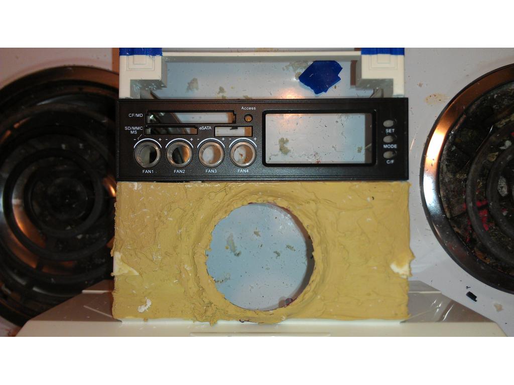
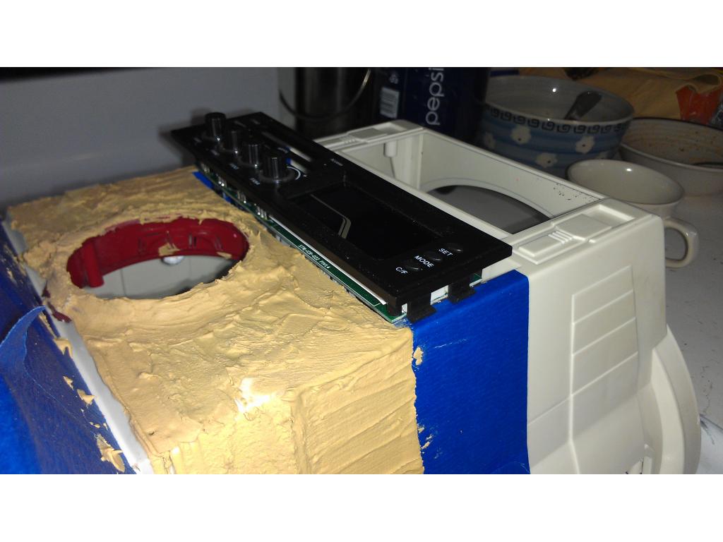
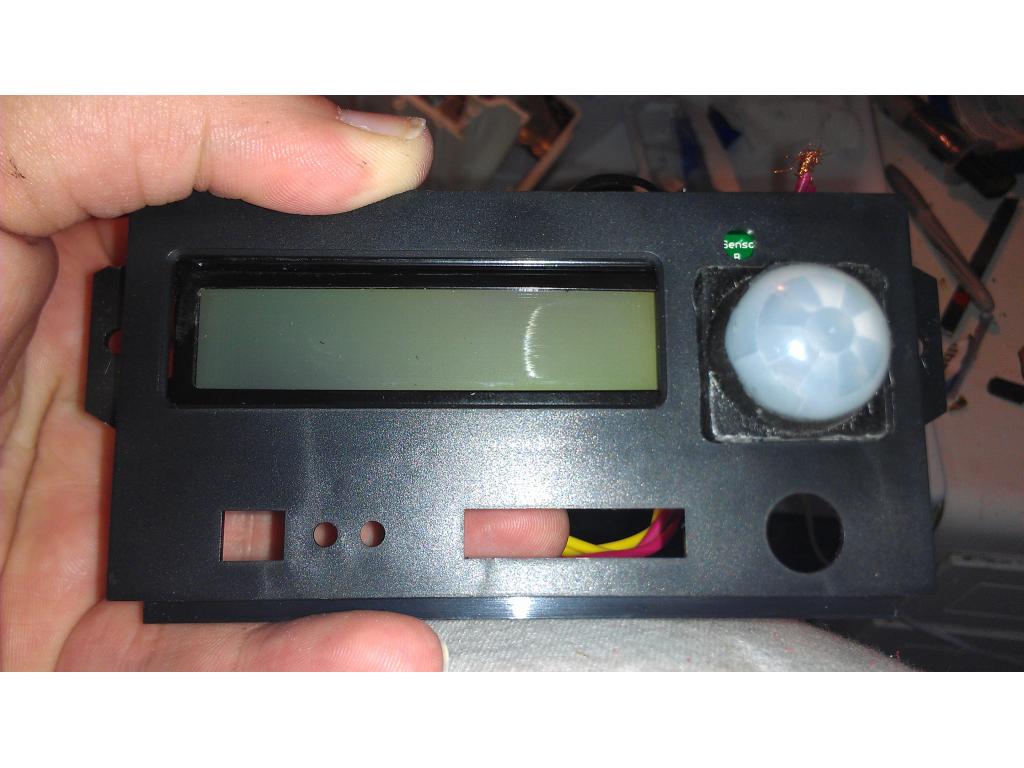
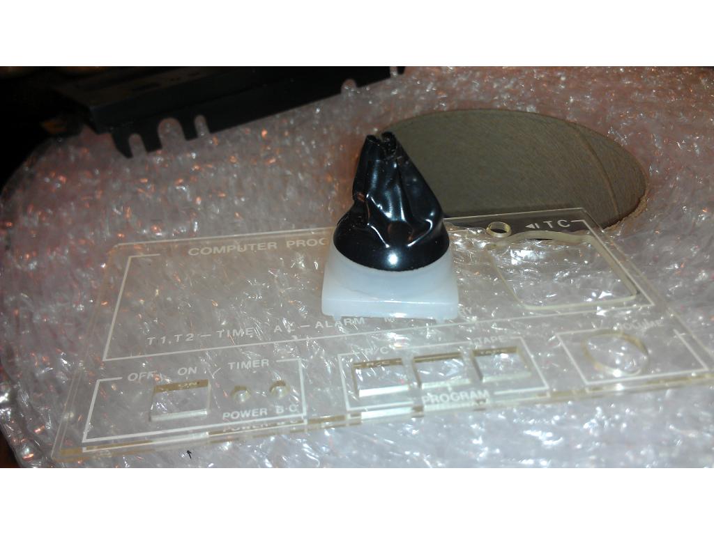
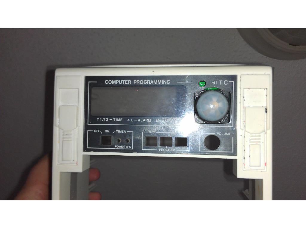
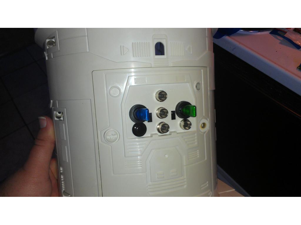
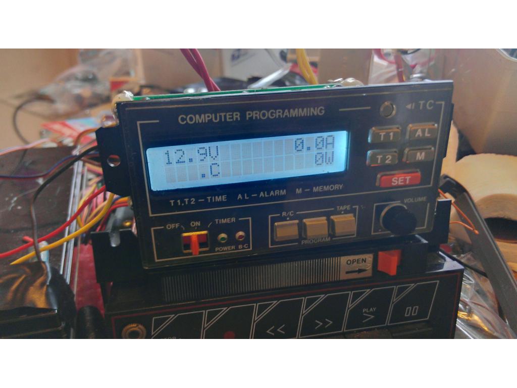
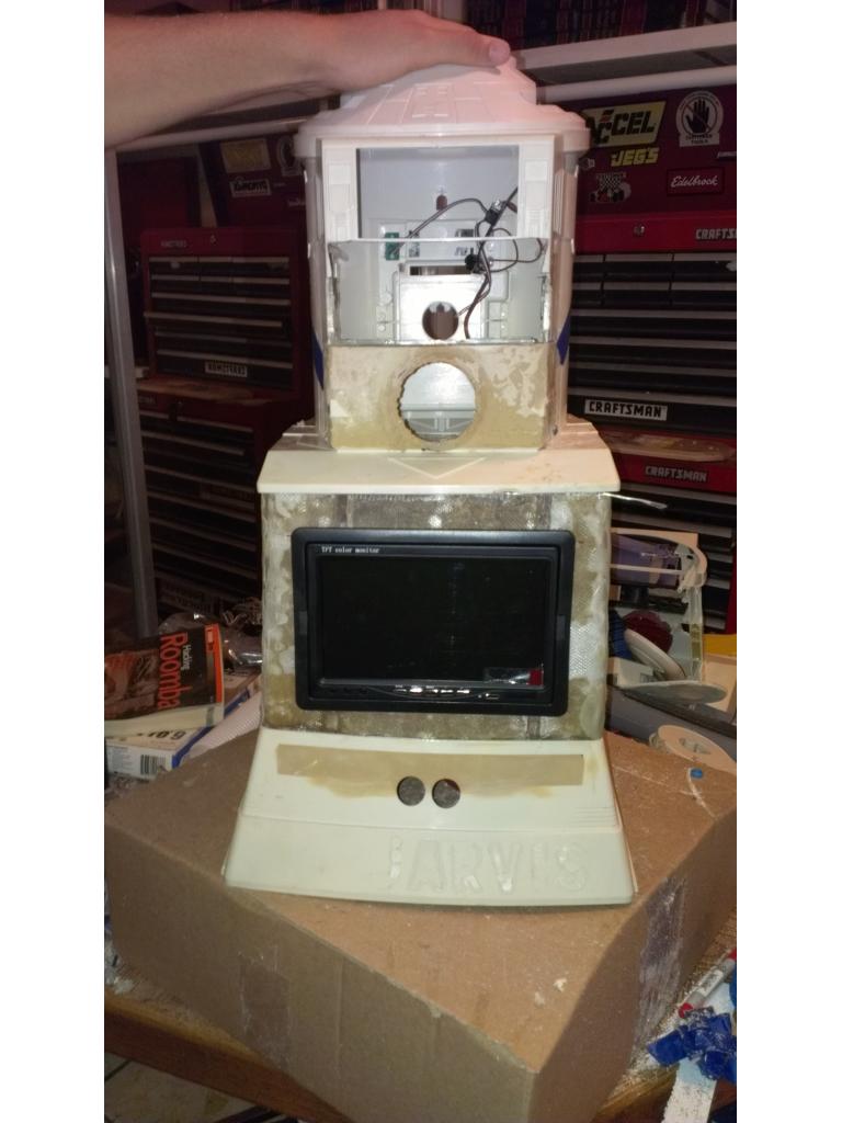
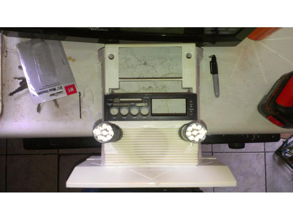
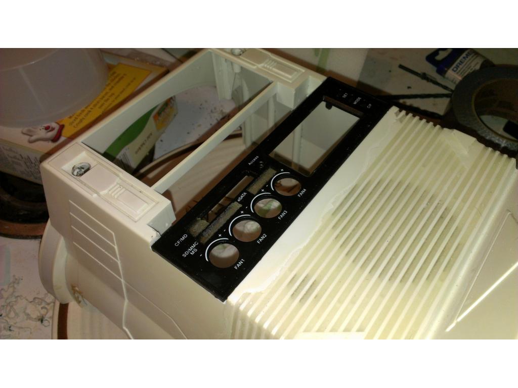
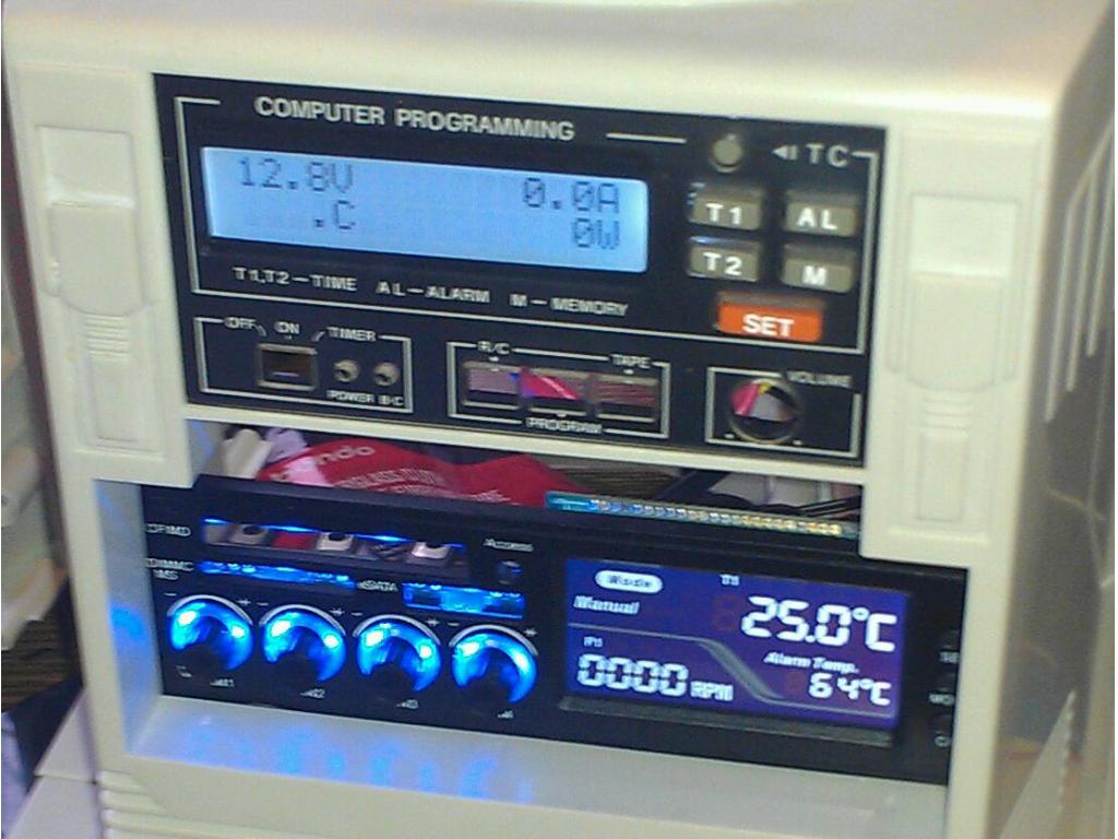
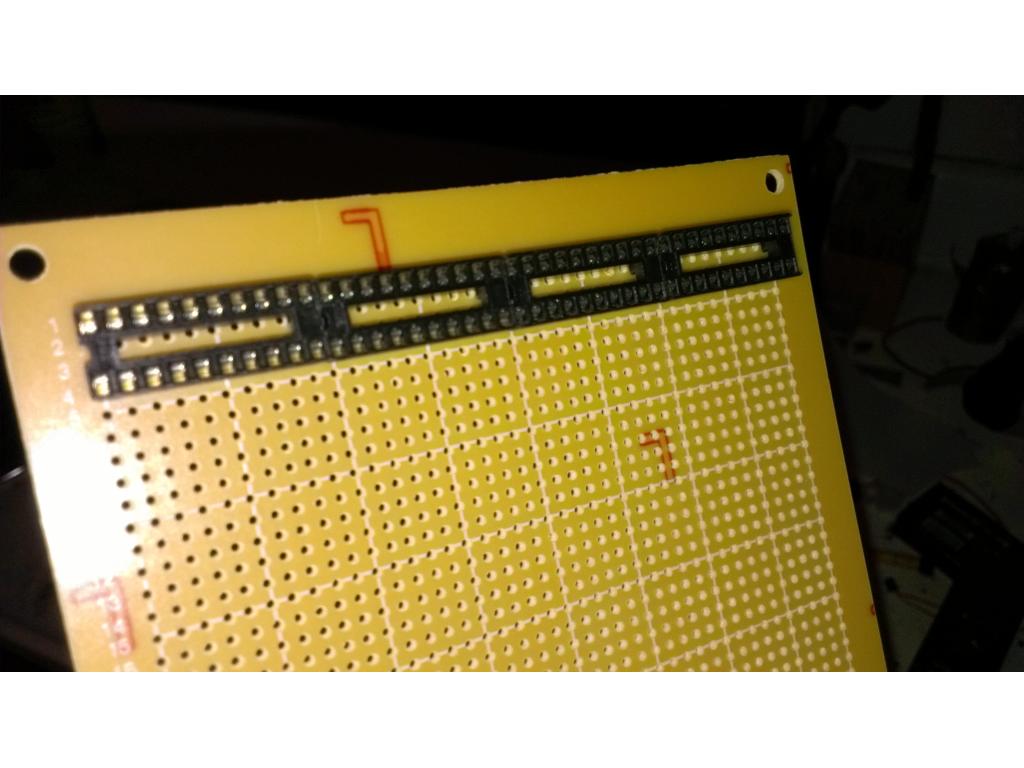
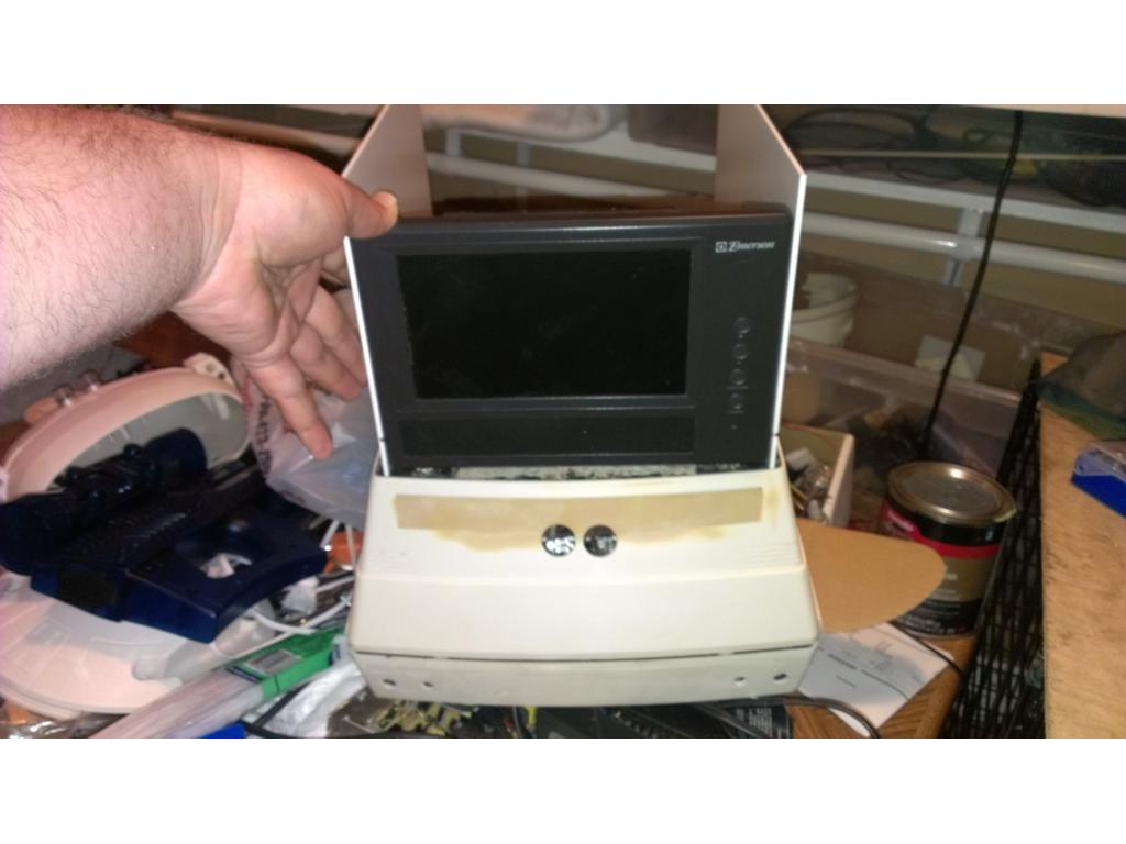
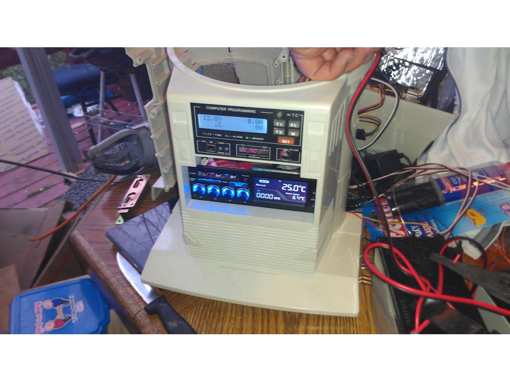
I modified the OEM LCD panel. Previously it would not light up like modern backlit LCD. So I purchased a LCD unit that perfectly fit. Once I got the LCD and LCD microcontroller driver it added up to about 45 dollars. The four buttons on the right are no longer functional but I planned on retaining the original power on switch , power on light and hard disk light.
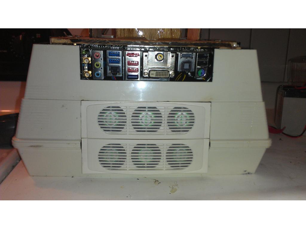
The bot needs cooling as there are 3 dc to dc converters , motor controller, ezb board , mini pc and HDD that generates heat. I doubled up the exhuast , 6 40mm fans from a now taller drawer hole. This should exhuast 30 to 35 cu ft a minute.

I epoxied together two 5.25 inch drive bay coolers that are quiet and advertised to move 18 cu ft.each.Now I need to mount my slim blueray player right over the fan controller. I must mount the 3 dc converters , motor controller, ezb. I want to use standoffs but they are hard to find locally.
Dude! That is sick!
I'm trying dude , this lol robot is very complex and not much room for all the things. I have not mounted any servos yet. I am salvaging some standoffs from smaller less important boards to mount my components. I'm going to epoxy the standoffs so my components can be unscrewed and bench tested or even replaced. I had my 10 amp hbridge come in which.I may use instead of the 1.5 that I got from dj. Here's a picture of the boards I gotta find a place for ...
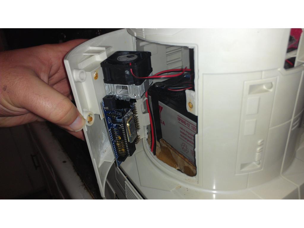
Any suggestions on if I should put ezb on the inside of the torso door or just try to keep everything in the base. I'm thinking of the fact I will have head and arm servos needing to be connected. So here is my proposed ezb mounting position for easy access....
i applied two layers of fiberglass fabric and epoxy to repair the rear wheel mounts. The.
-Josh
I am Drooling! that is just wicked! I would recommend mounting EZB for easy access...and label your wires...and use the notepad feature in ARC....when you have a gazillion wires on your EZ-B troubleshooting will be a pain if you don't have things well documented and have easy access to the EZ-B....you will be making adjustments or fixes or how you want to map your wires when you start plugging everything in. you may want to make room for that 2nd EZ-B with the rate things are looking.....nice work!
v/r
Kevin
Thanks man, this is tip of the iceburg but i want to make the best one out there lol. oh yea i am known to be a overdocumenter I will make paper tags for the wires because there are far too many to keep up with. my fan controller alone has 25-30 wires that are all black. I will have power for ez b, power for motors, servos and motherboard. thats another 4 pairs and i havent even mentioned any servos yet lol right now I gotta figure out how to mount the slim blueray drive above the fan controller and below the control panel. I will need to make a mount somehow. More work for tommorow! - Josh
I really like the EZ-B on the inside of the door, that really gives you excellent access. Which I have found out in my omni, is really crucial.
Great project however You can't have the 6volts battery parrrell and series at the same time. Your schematic is a dead short across the batteries. If you want to do what you want, you would need a relay to have the battetys in parallel when sourcing the ez-b but switch to series for charging while disconnecting the load.
@drwass I descided to use voltage converters , drops from 12 to 10-1v adjustable. So all my batteries will be 12v. @brett yea I'm liking the idea , I will need to do some cutting to make sure I have ample space to plug.in wires.
I think that's the smart way to go jstarne1 ! Now energy from all the batteries will be able to be used . J.W.
J.W.
My only potential problem which.May not even become an issue is my dc to dc converters are rated 2amps each. So I must me sure not to over amp. The drive motors dj had no problem with but I'm wondering what kinda juice they will draw with the 15 pounds of electronics and batteries onboard. Anyone know average current draw the motors usually use at a close to original weight?
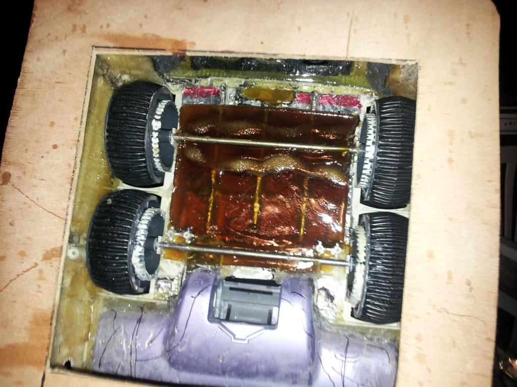
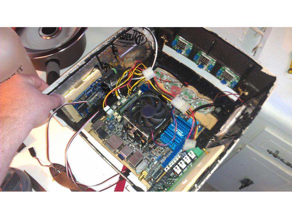
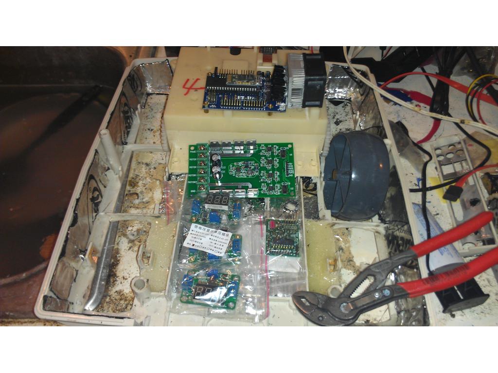
Okay updates ! I'm mounting all of the electronics. The motor controller on one side and ezb on the other. The voltage converters that allow me to drop the 12v battery supply down to a usable 6v are lined up agianst the front. I will be doing some more dynamat as I just recieved the 4 sq ft I bought on the internet.
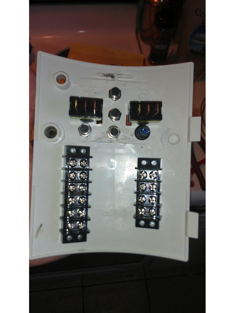
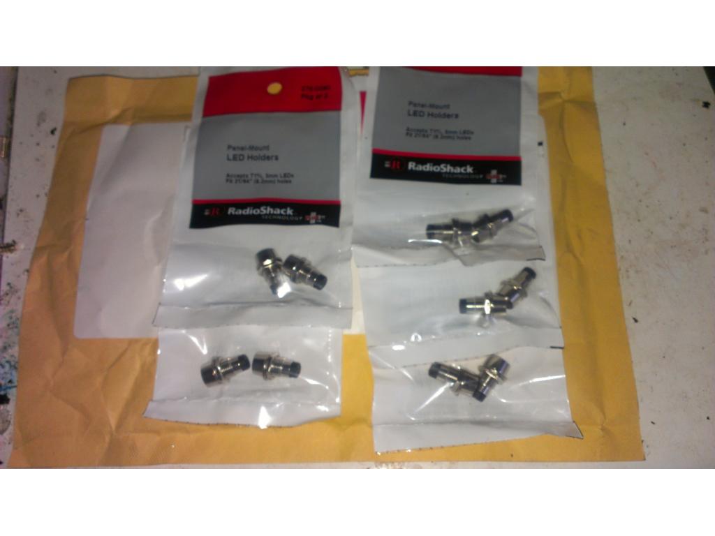
Ok I wanted to utilize the holes in the back door so I installed led holders to indicate pc power on , ezb status light , primary power on and HDD light.. one is a momentary switch to shutdown the pc if it freezes. The switches are going to be arranged so I can remotely control the robot from my w500 tablet.
Looking great.....where did you get your voltage converters? Very neat work!
Nice layout.

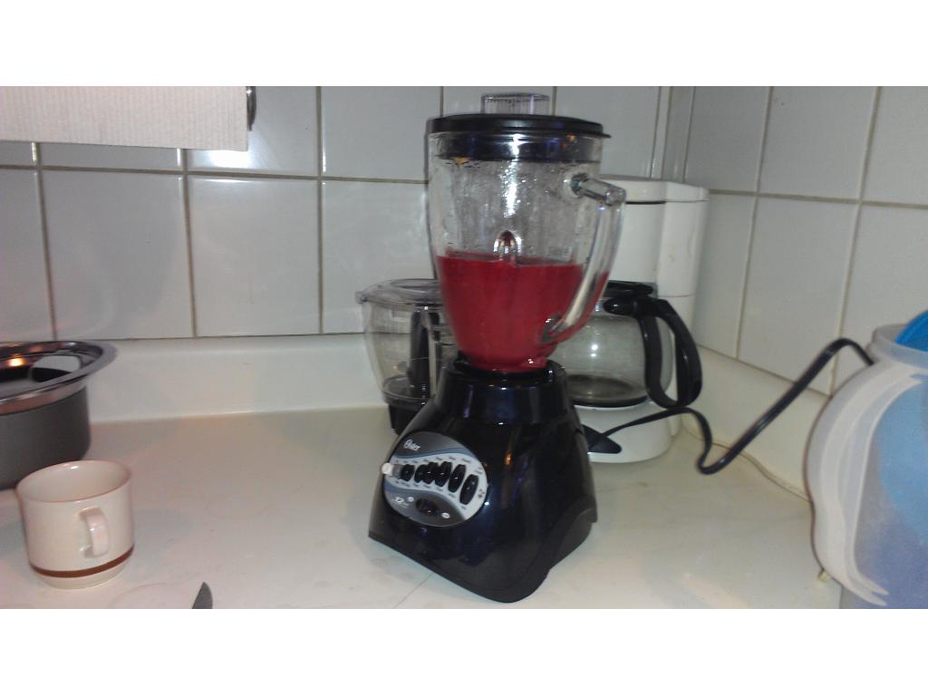
Having a smoothie makes progress go smooootherI purchased 3 voltage converters for 30 dollars shipped. So they are cheaper and allow you to use a 12v battery and get a longer runtime. http://www.ebay.com/itm/150748060772?ssPageName=STRK:MEWNX:IT&_trksid=p3984.m1497.l2649
I reversed all the fans orientation and glued in the mount with epoxy. Now my cooling solution is finished. I.have the led holders in place but I have not descided what colors I'm going to use yet. All the LEDs I have at the moment are high output and that's big overkill for indicator lights.
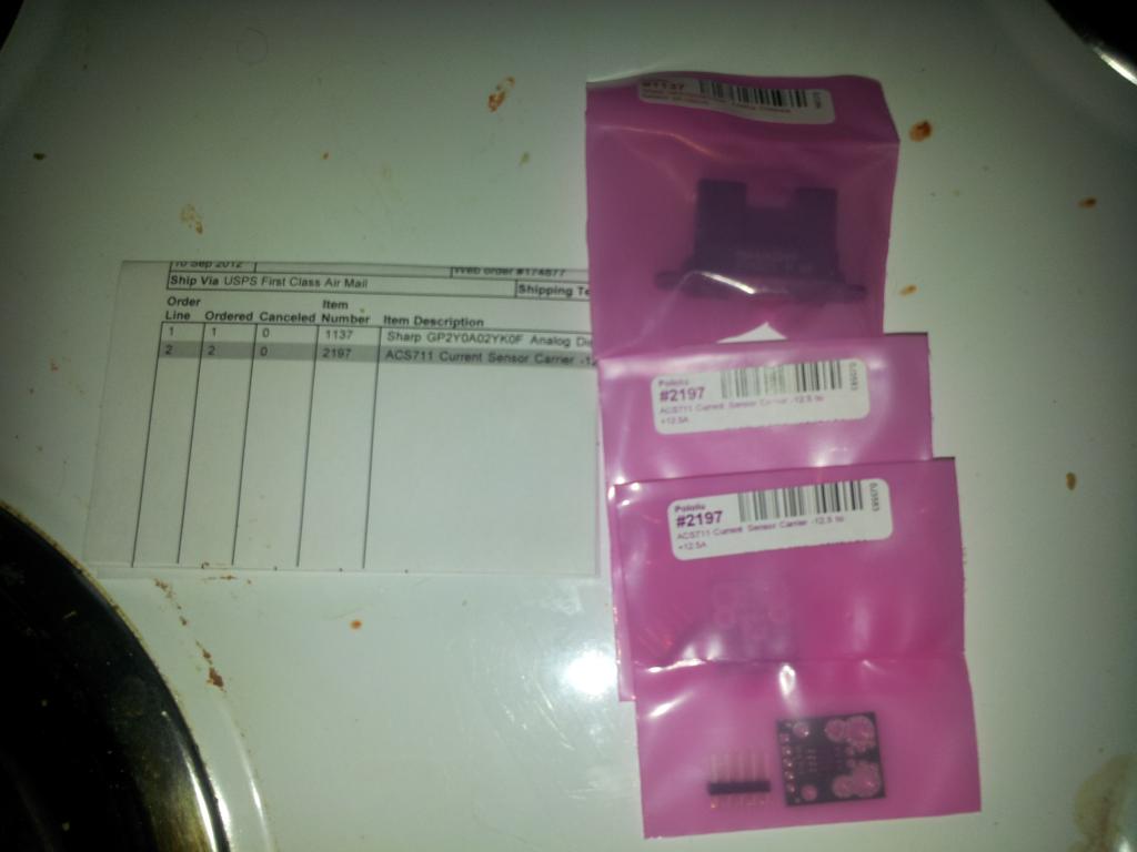
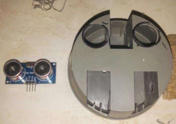
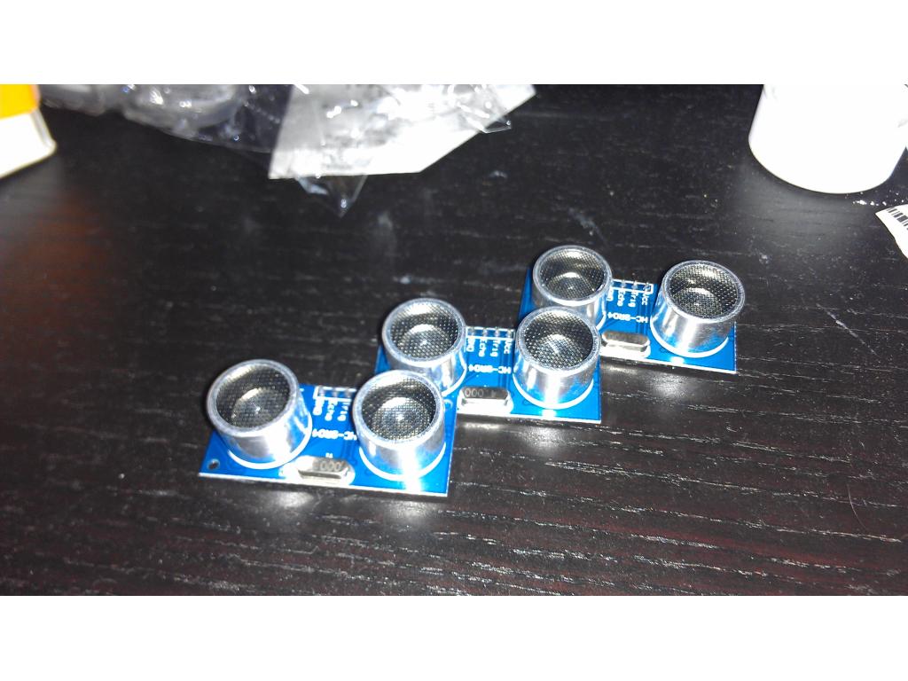
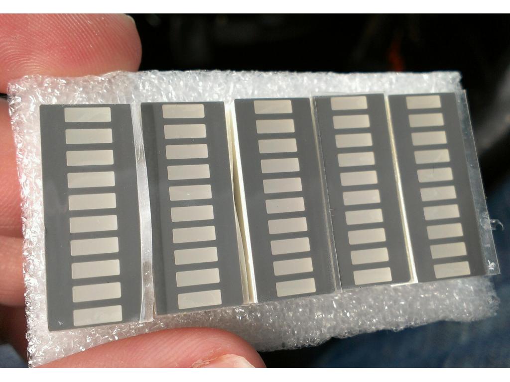
Ok somthing I was waiting on ! Back to building. The additional three sr04 ping sensors came in from Hong Kong. With as much as they ship you would think they would make international imports more efficient. Anyways here they are...
I planned on facing one forward for radar , one for stair avoidance on the front bottom and the other two sensors use is not definitely descided yet but previous pictures I drew threw ideas out there.
That LCD front is awesome! I have a serial LCD laying around i could put on mine! thanks for the idea!
Do those voltage converters get very hot (waste energy to heat)?
I have a pair of 12v 17amp/hour batteries that are currently wired serial for 24v, which is what my wheelchair motors want. I also want to provide auxiliary power to the netbook the bot will be carrying (19v) and would like to also use the same batteries to provide 7.2 to the EZ-B and maybe 12 to some fans.
I figured I could pull the 12 by just connecting to one of the 2 batteries (will that work if they are wired in Serial -- pull 12v + and ground from between the batteries? Seems to look right on my meter, but it has been 30 years since I did any electrical work other than replacing a light switch or ceiling fan). If that works for the 12v, then another converter to go down to 7.5 (maybe from the other battery, so they discharge somewhat evenly)....
I am still looking for a charging solution too if anyone has any ideas to charge 1 24 or 2 12v high amperage batteries without taking all night but also without breaking the bank account....
Alan
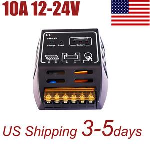
What about something like this?
Charger
Thanks Bret. Price is right. It would take 4 hours to fully recharge. I'll have to come up with some kind of self plugging docking station so it can go patrol and get back to the charger on its own if the house alarm goes off while it is charging, but there have been a lot of ideas thrown around about how to do that, so I am sure I'll be able to figure it out.
Looks like this seller has a bunch of differnet chargers. I'll look through and make sure this is the most appropriate.
The previous one I had found (that would have had 2 hour charge time) was $90, and I would rather spend $30 on the charger and put the difference towards a 2x25 H-bridge. Once I have those items I can really start my big bot build.
Alan
I think Drwass answered my question a couple pages back about using the batteries as both 12 and 24 at the same time.. Answer is no, although he was critiquing a more complex circuit than I was thinking of.
Can anyone recommend a good site or book on basic circuit design? Just looking for things like voltage regulation, use of relays, transistors, capacitors, etc... I don't need anything that gets into IC design or higher level stuff. I just need a refresher course on the basics I learned in high school.
Alan
Just testing no it didn't get hot. Are you 24 volt.motors? There are voltage steppers that would work fine for you and I see them on Rabat at 3a and 5a if you needed more current. The 2 amp should be plenty for a netbook though.
Yeah, the motors are 24v, (they can haul 300 lbs, plus their own 60lbs...)
I think you are right about 2amps for the netbook, I'll verify this evening. I have a car converter for it that steps up 12 to 19 volts, vut I know it wastes a lot to do it, so going down to 19 makes more sense to me.
I eventually plan on doing what you did and putting a mini atx in, but the netbook doesn't get much use since I got an Android tablet and a laptop from work not much bigger than the netbook with twice the horsepower.
Alan
@alan so did you.confirm netbook draw , on my tablet charger max is 1.8 amps but.I'm sure its using less than that.
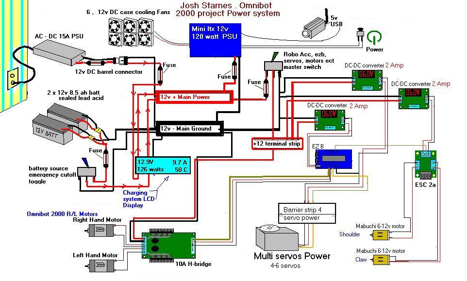
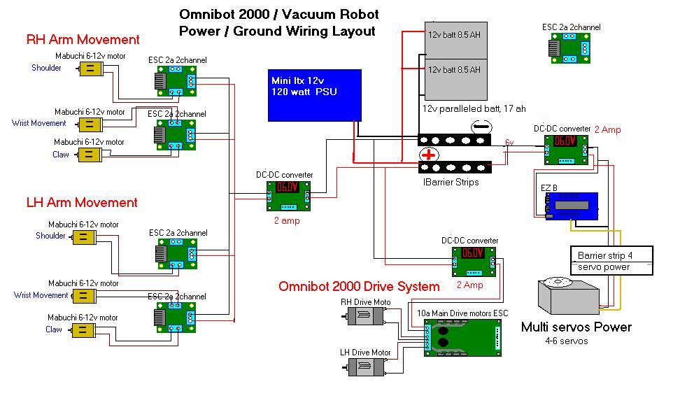
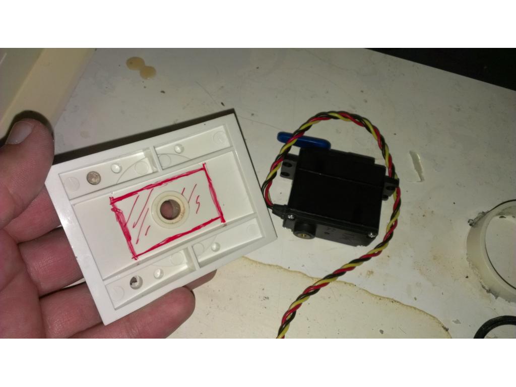
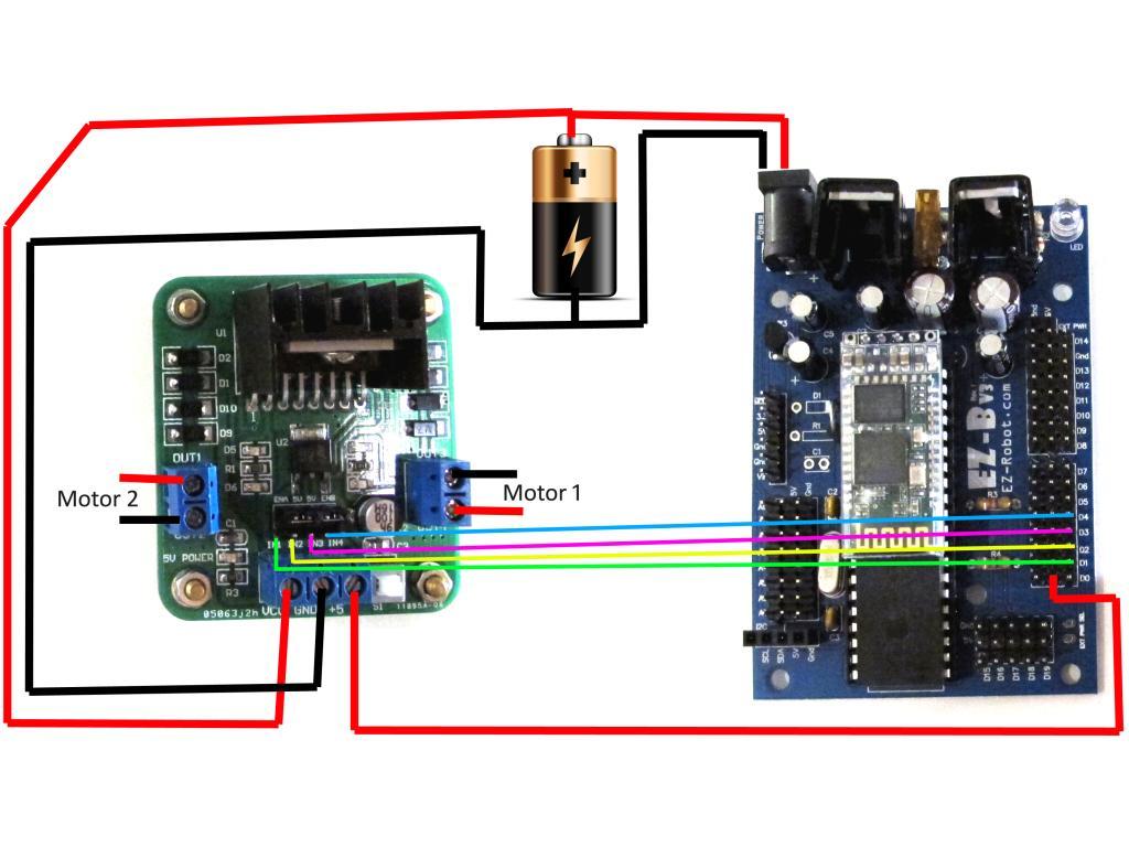
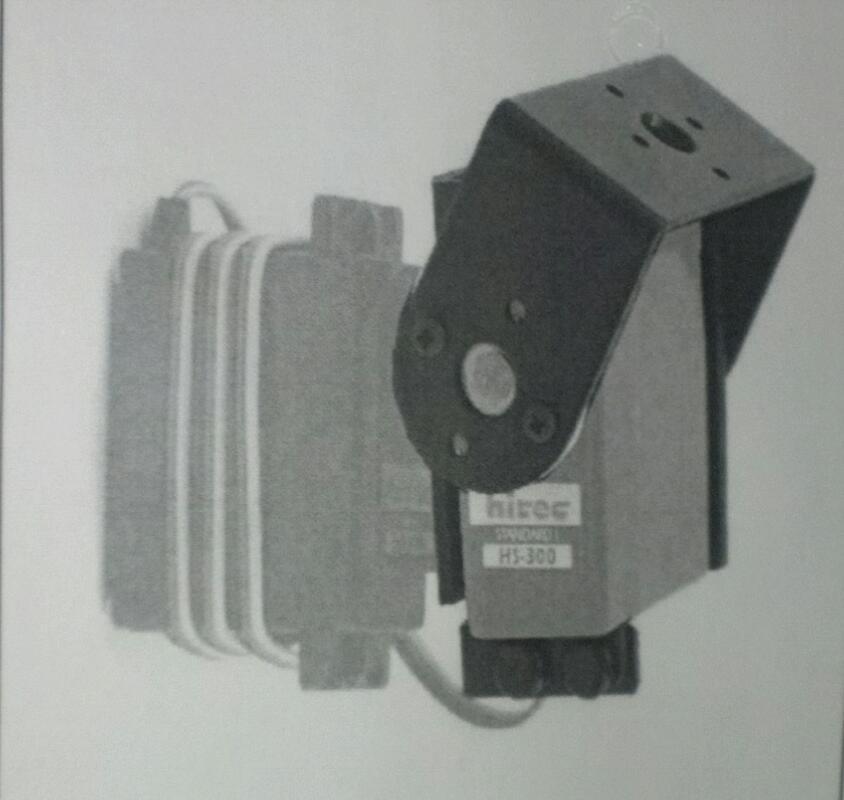
Ok so I'm "thinking" of leaving in the OEM motors for claw and wrist rotation . I came up with a wiring diagram today at work. In.this diagram all powered units are accounted for except my front LCD display but that's 12v anyways. I'm if I can get a servo to move slow enough I will put two high torque servos in place of shoulder motors any thoughts are appreciated.
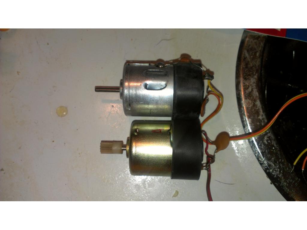
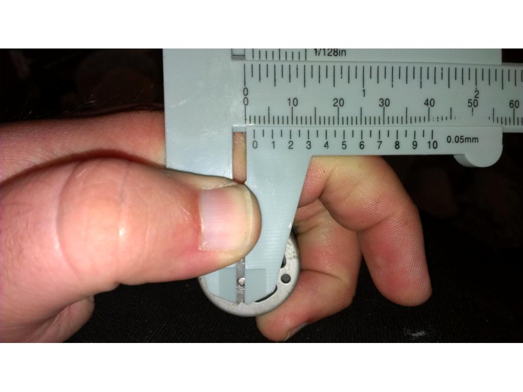
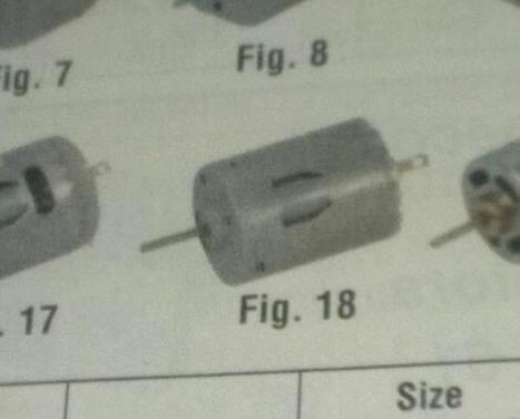
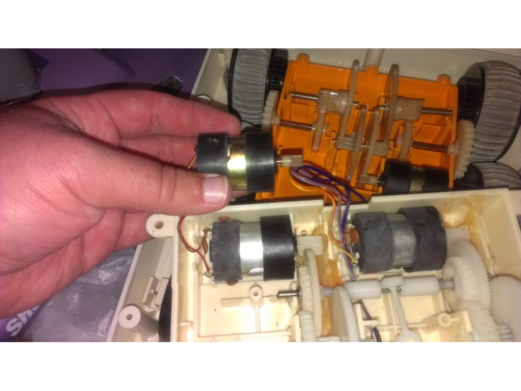
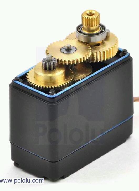
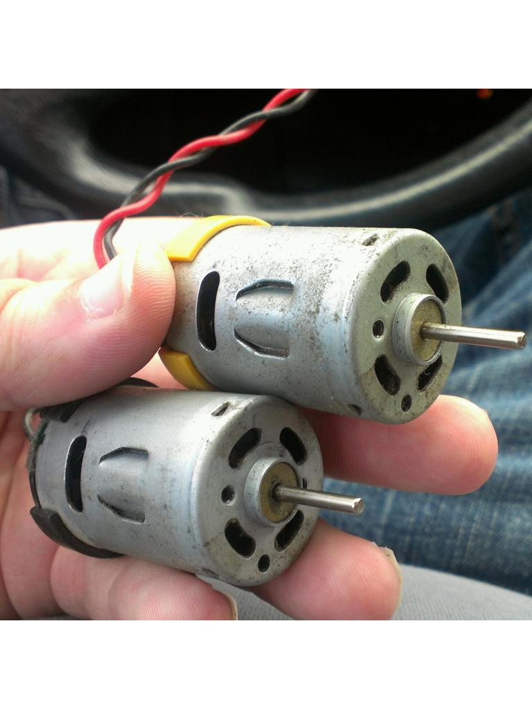
Anyone know the width and length of the motors in the arms? One arms motors are bad. Or ill just buy a whole motorized arm. And what size thickness and length in mm for the drive motors. I believe I.have found higher torque upgrades but I gotta know the exact size to know if I can fit it in the tranny easily. this is a backup plan in case the OEM motors are having trouble pulling around the extra 20 pounds
Netbook draws 1.58 amps, so no problem with the DC-DC converters. Nice find.
Alan
Have pics of your bot? Or design?
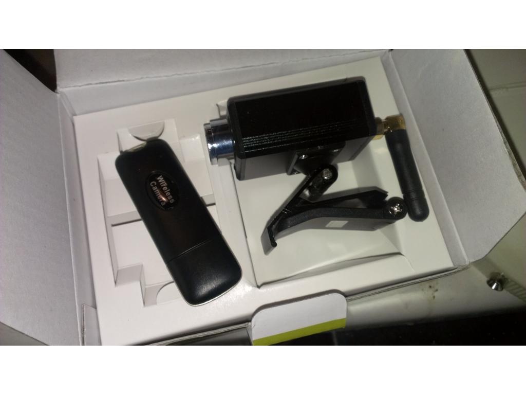
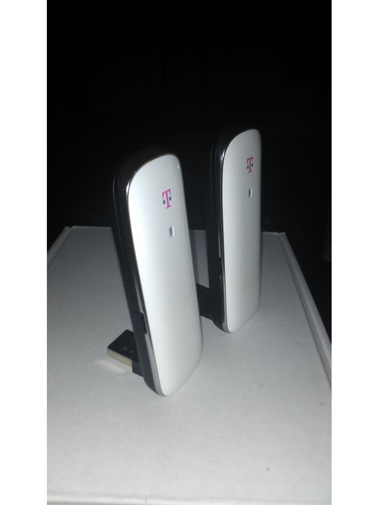
Ok I have a few updates. first.I caught a great deal to get.three usb 4G data sticks for .99 cents. The idea is.to use.this as a longer range / endless range form of communication I can either use the web portal or direct remote desktop from tablet or phone.
These data.sticks are also usb hard drives since they have a SD card slot for up to 32 Gb memory. The sticks have GPS satillite tracking as well if that could really ever be useful.
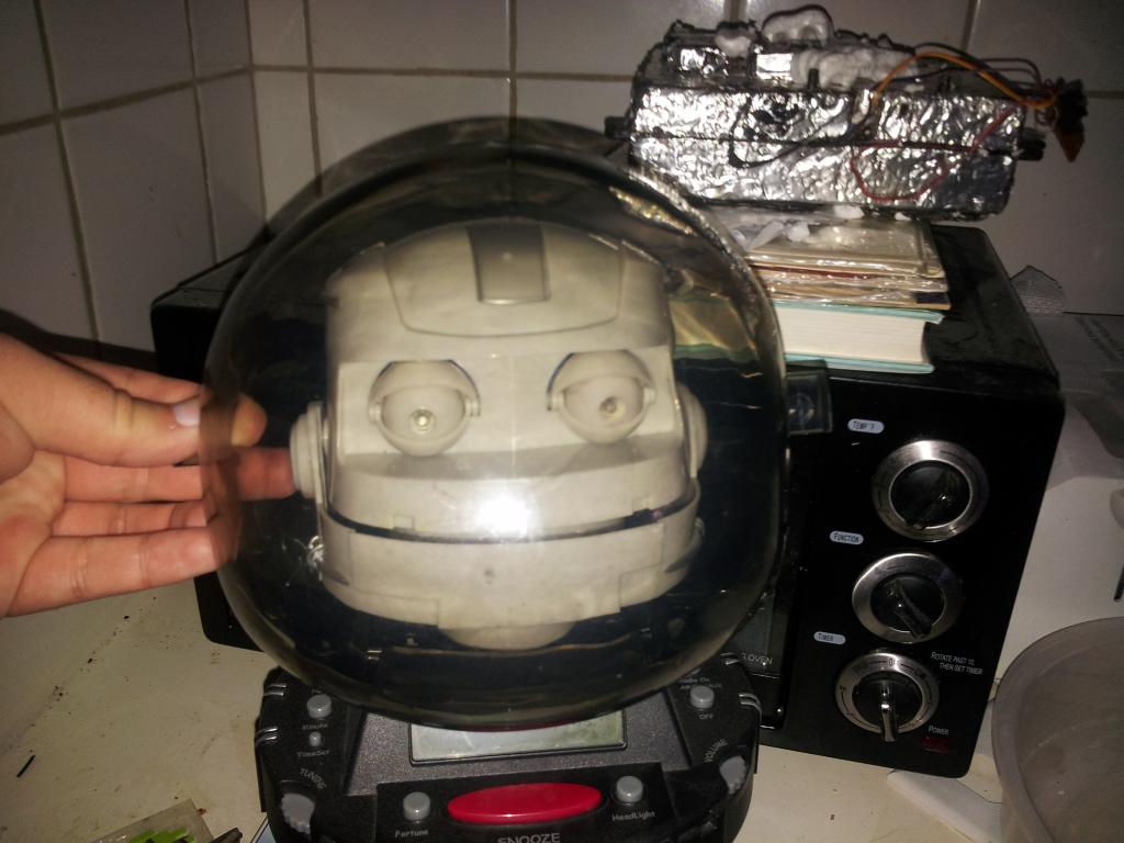
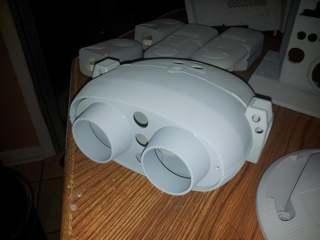
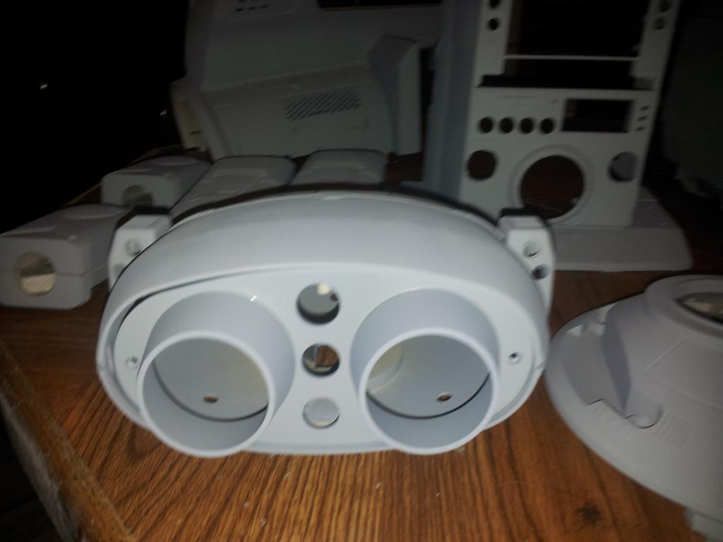
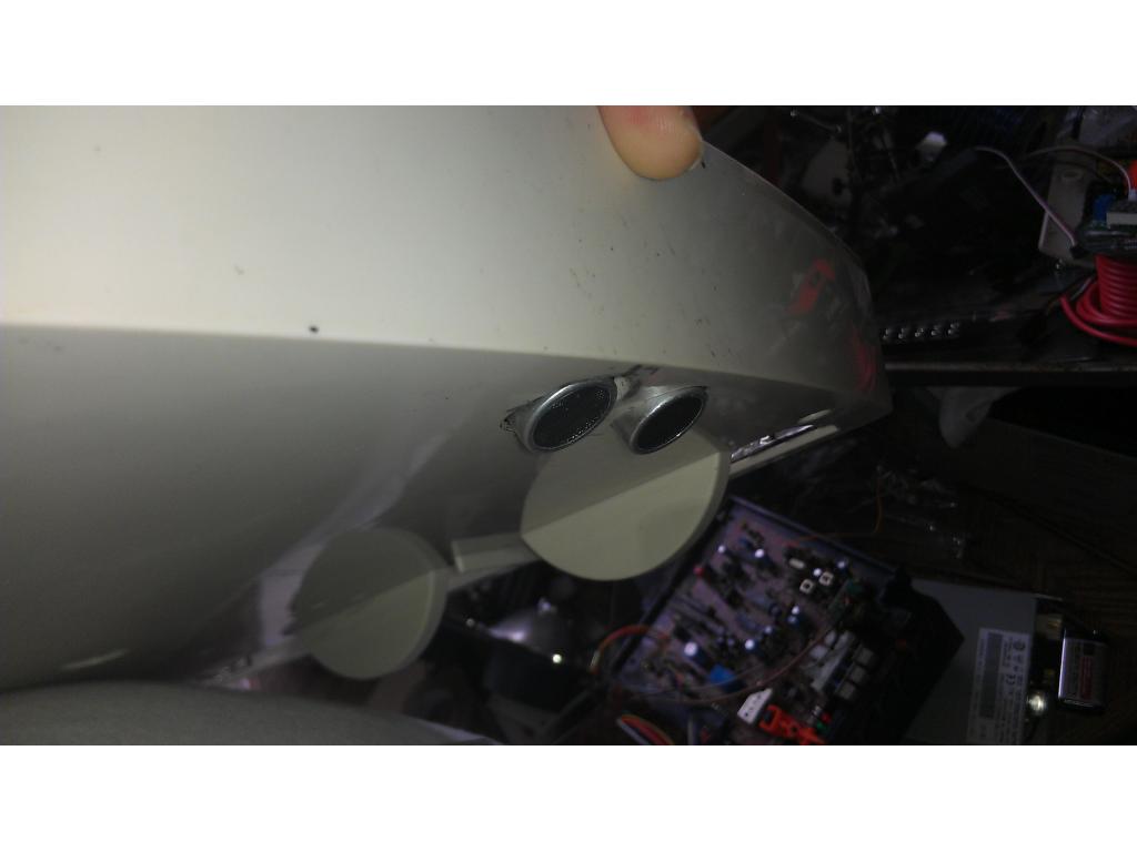
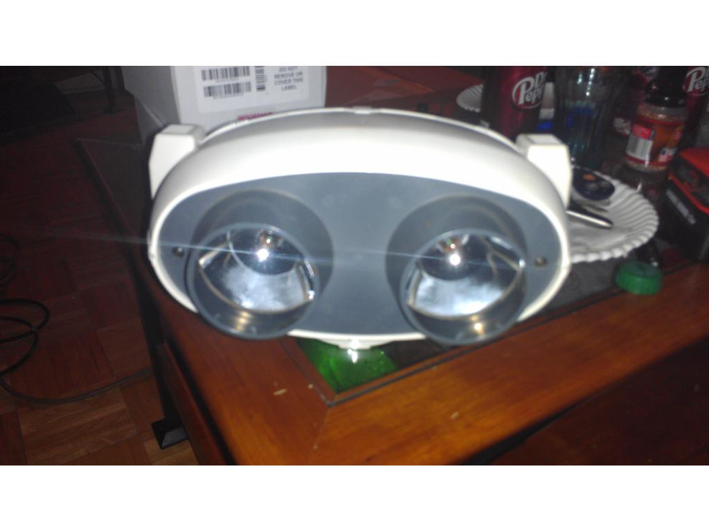
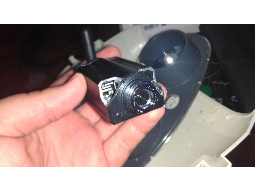
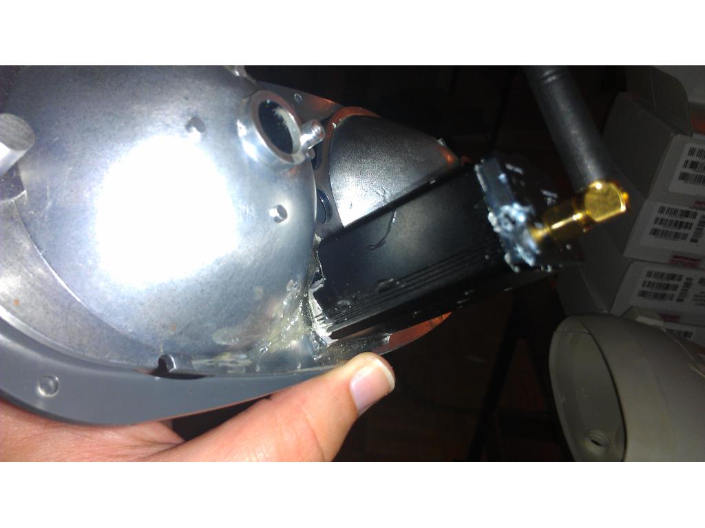
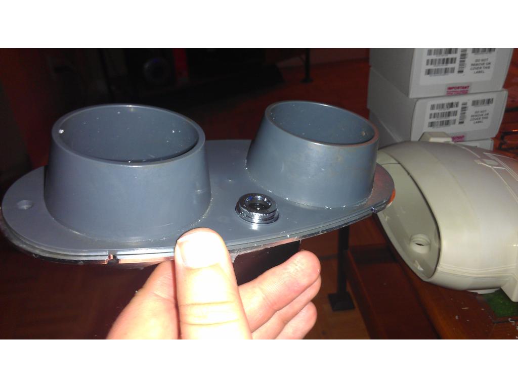
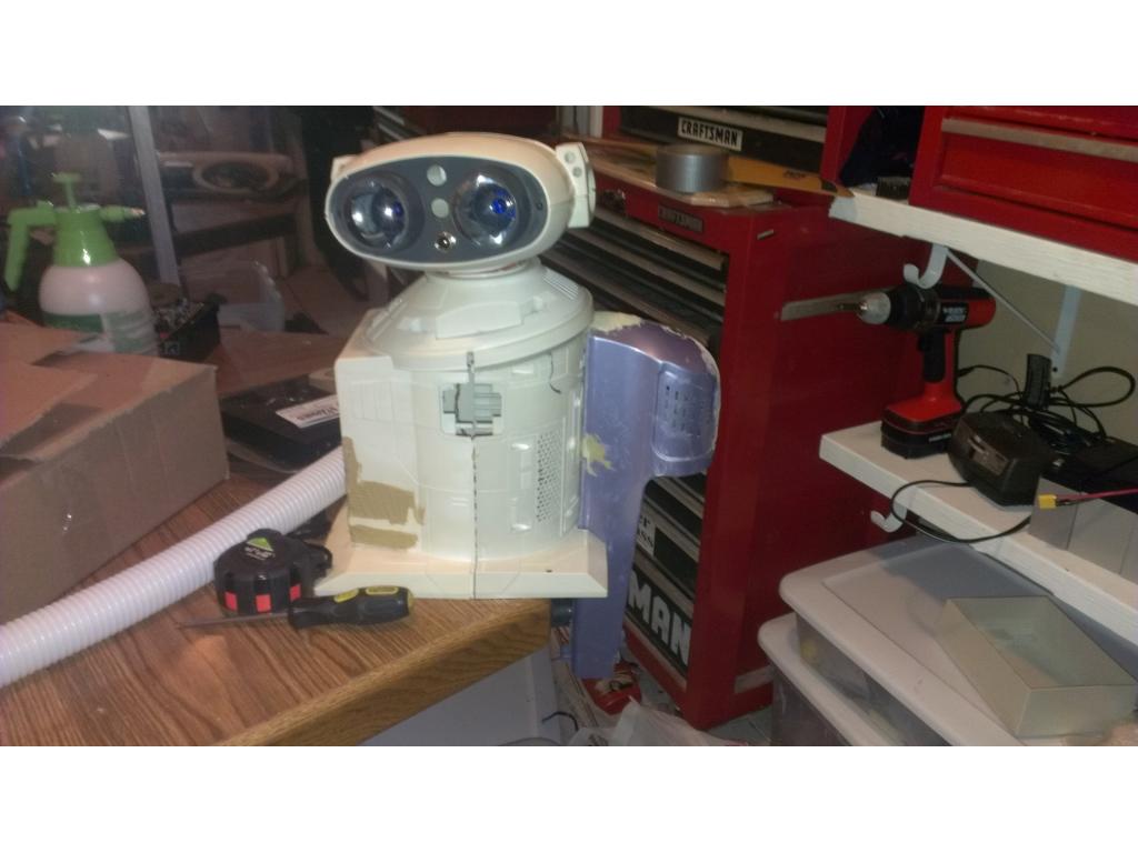
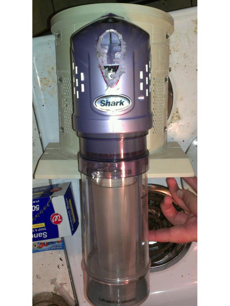
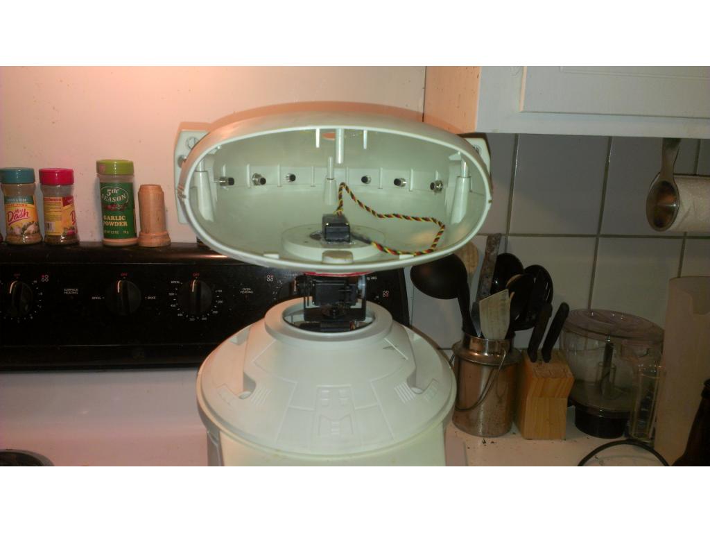
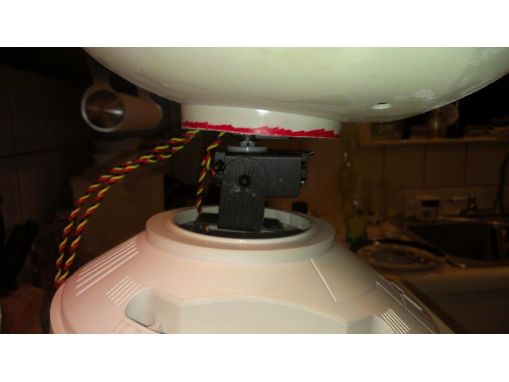
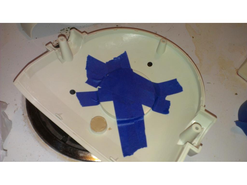
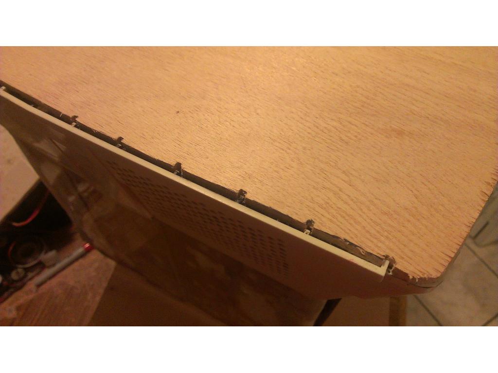
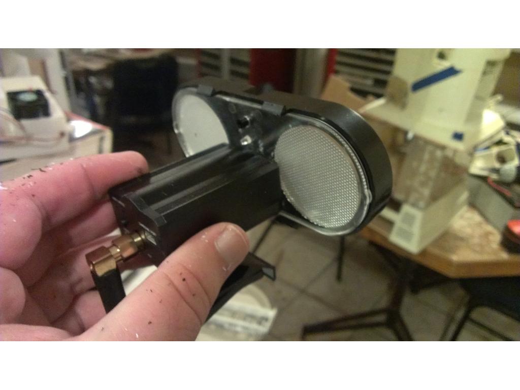
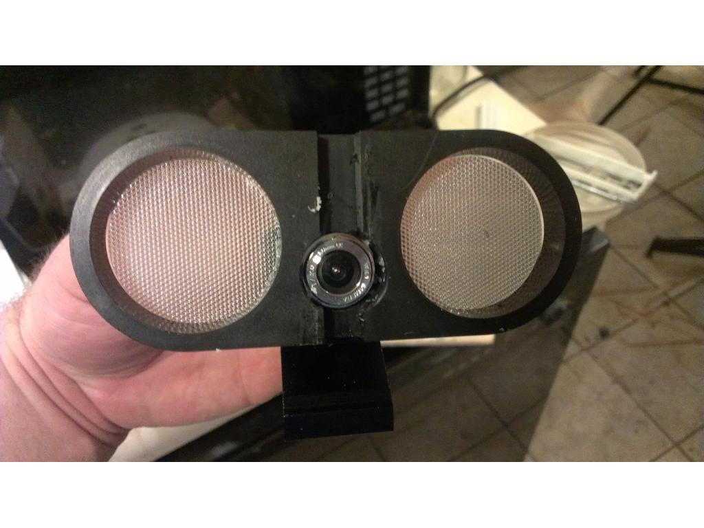
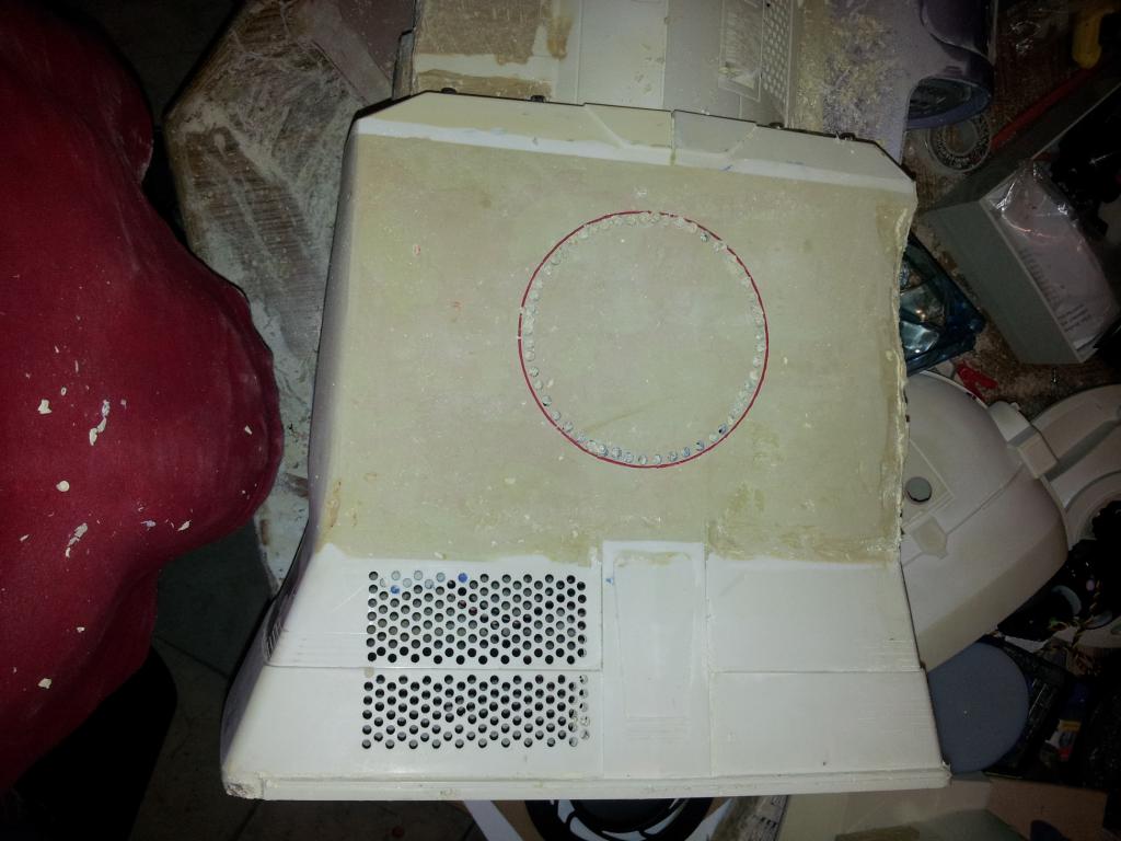
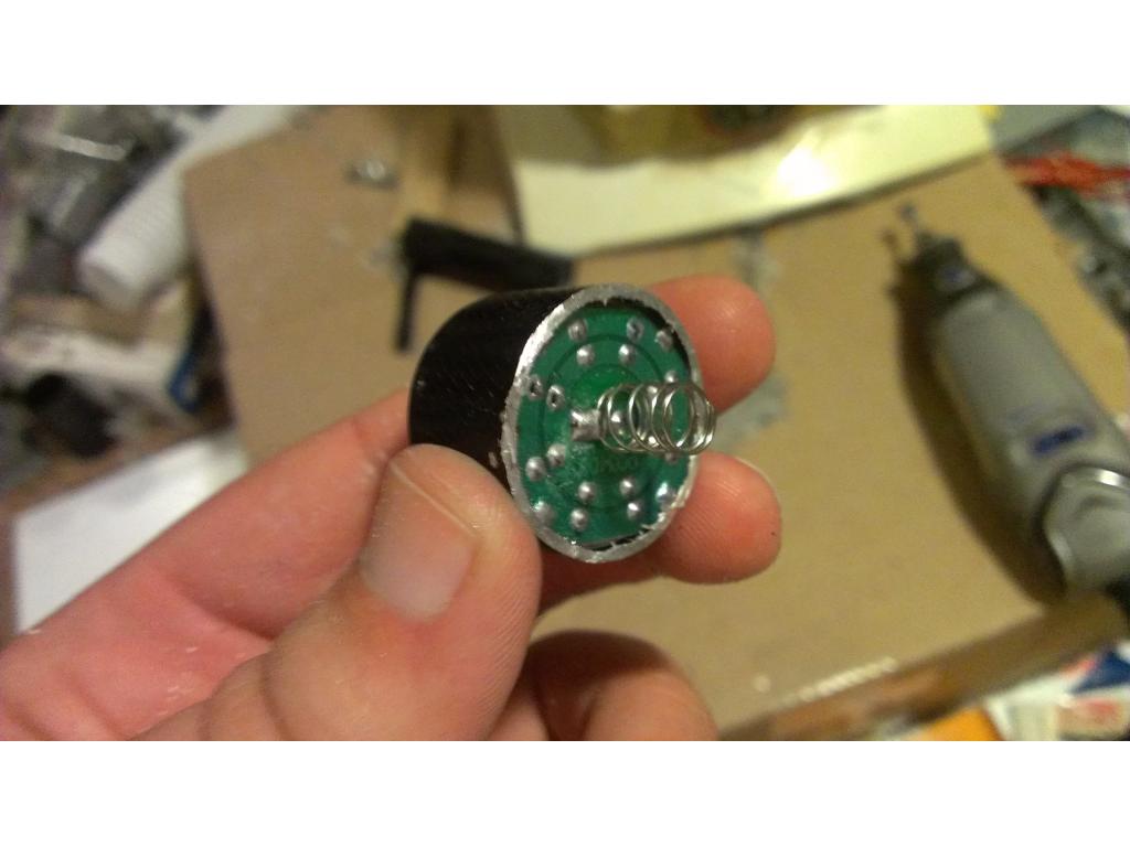
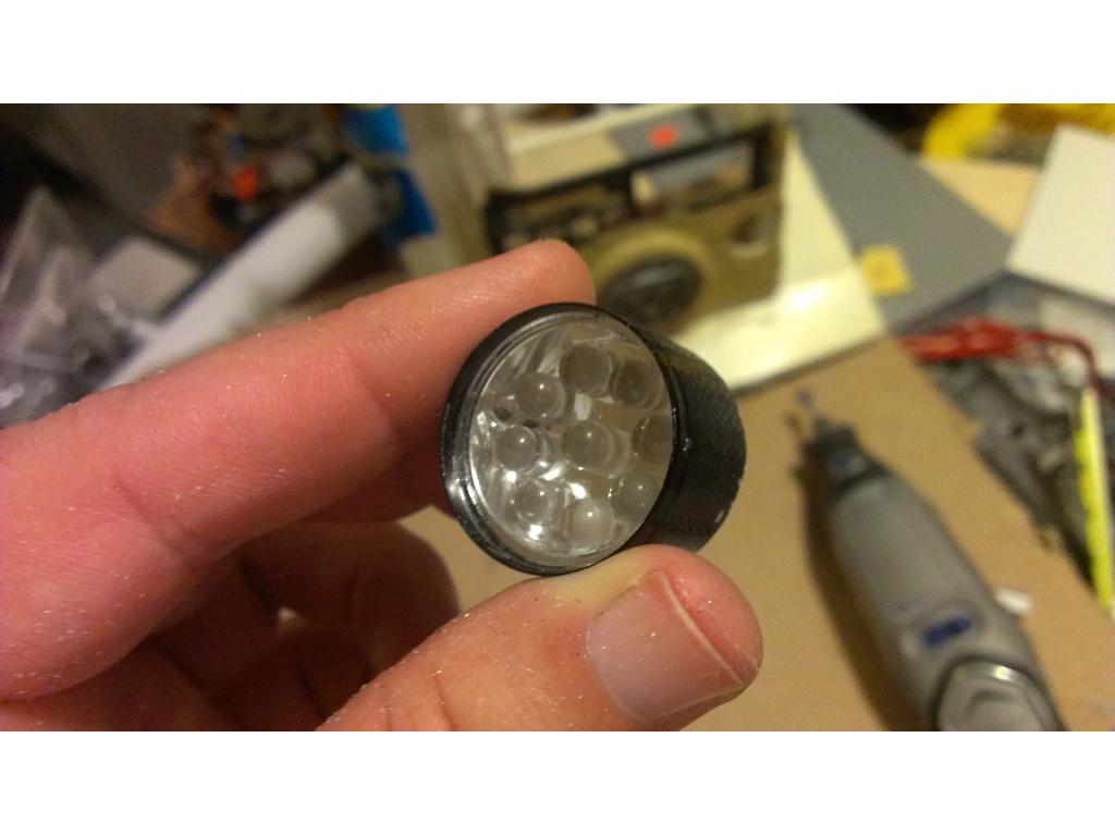
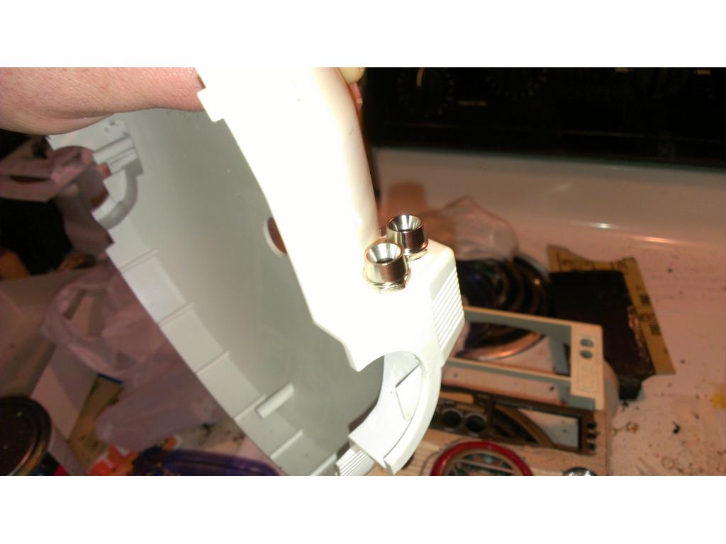
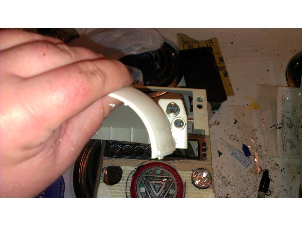
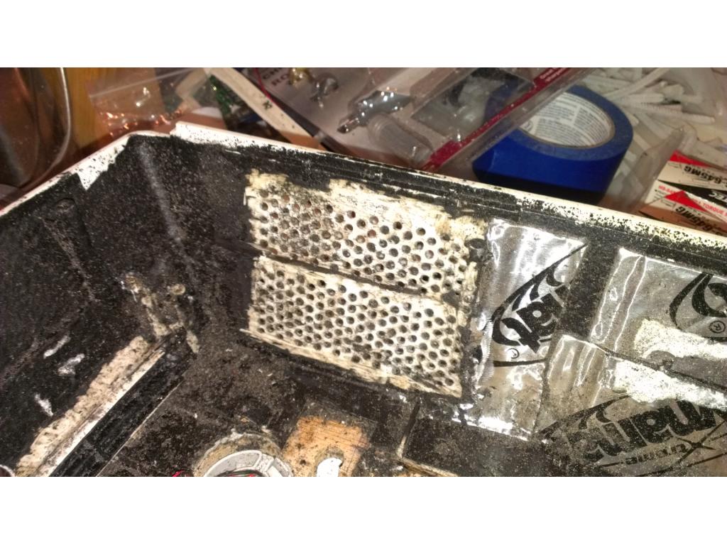
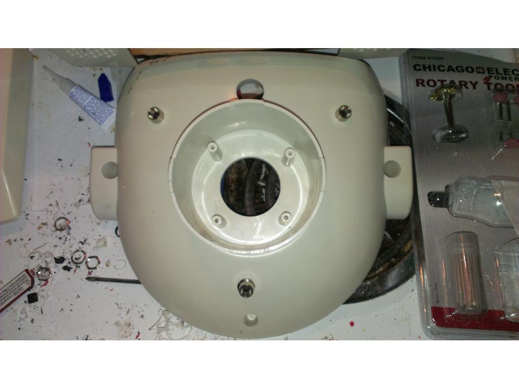
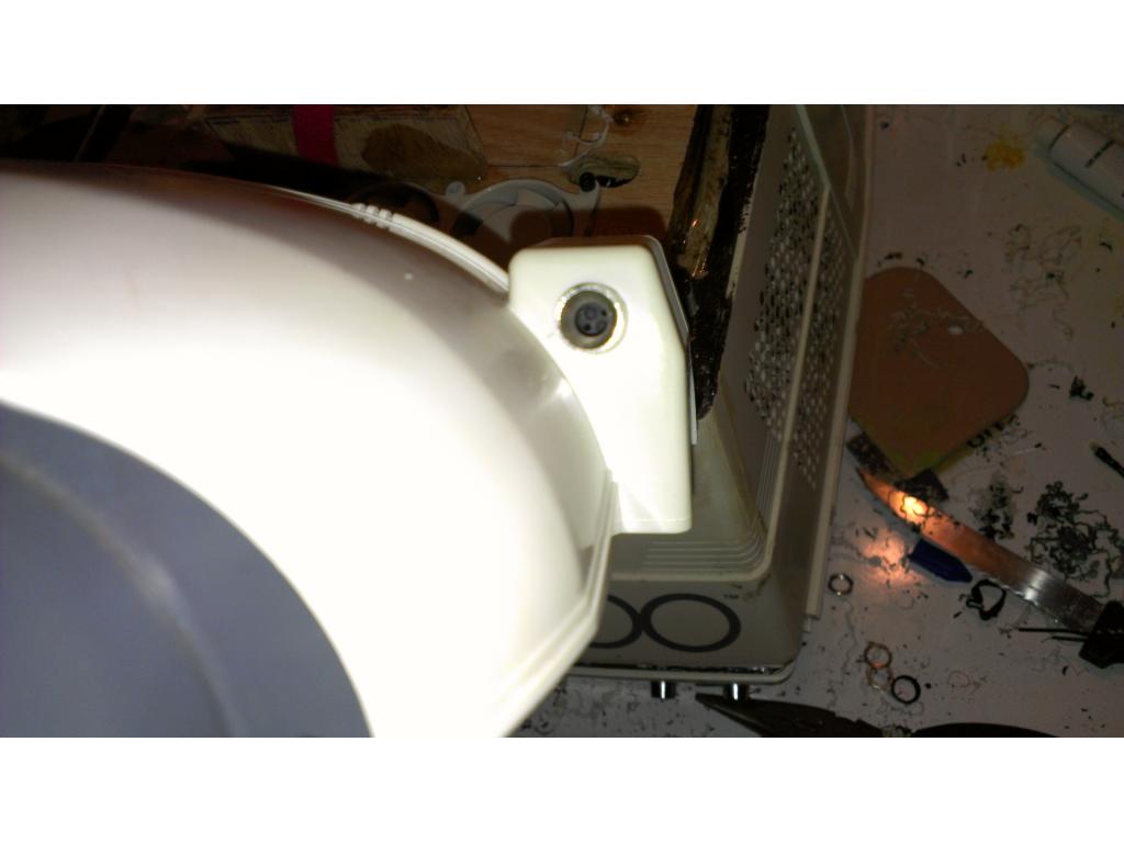
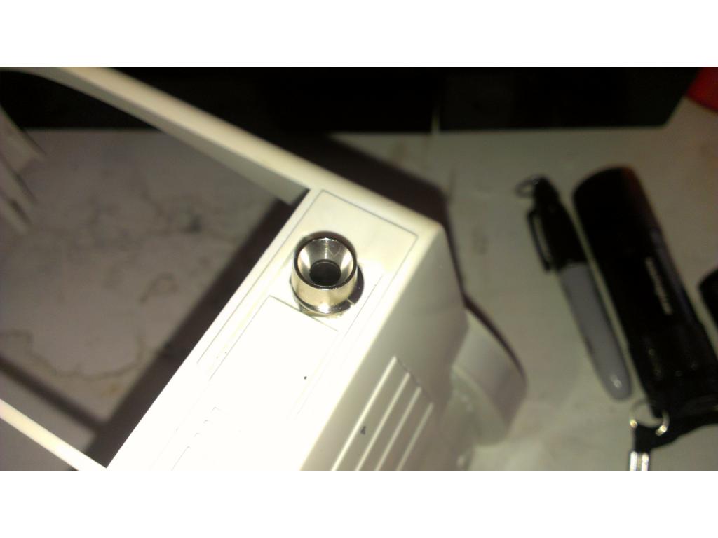
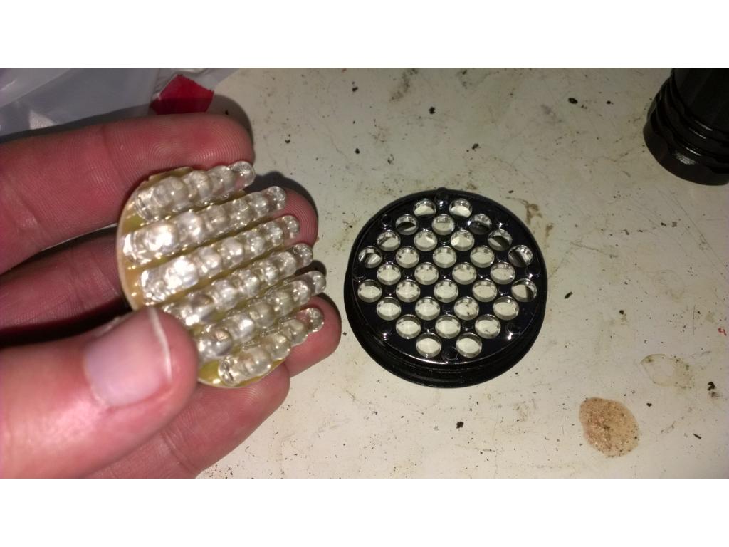
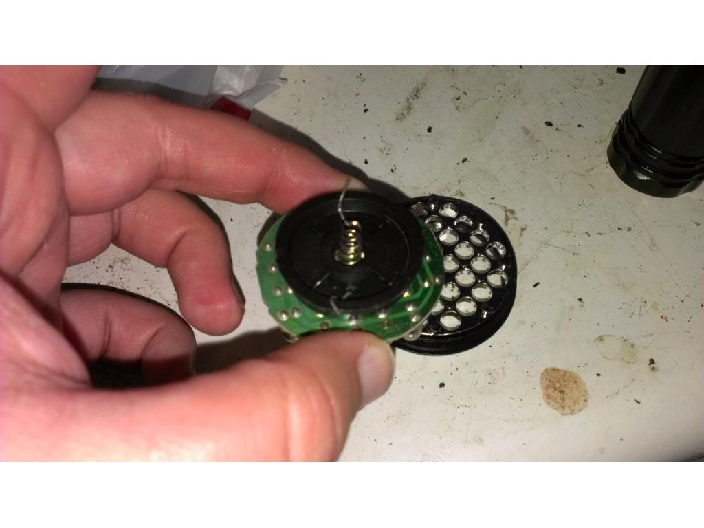
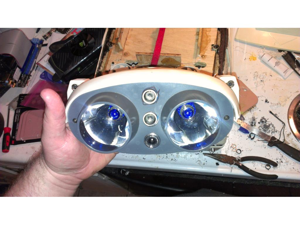
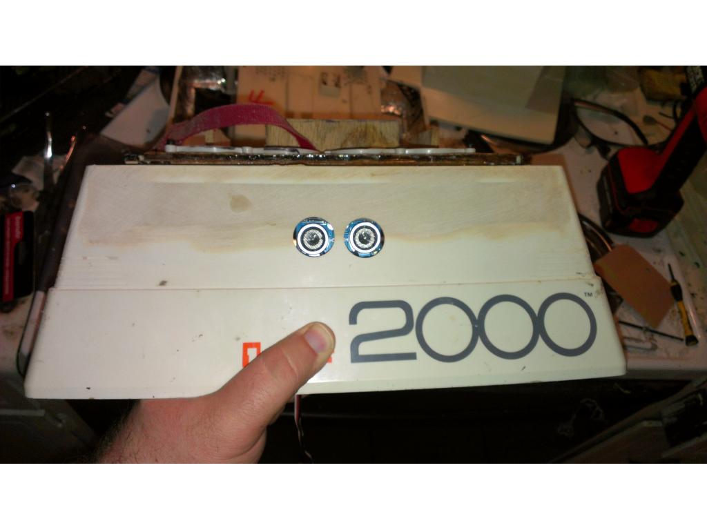
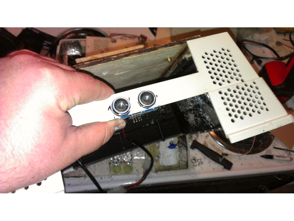
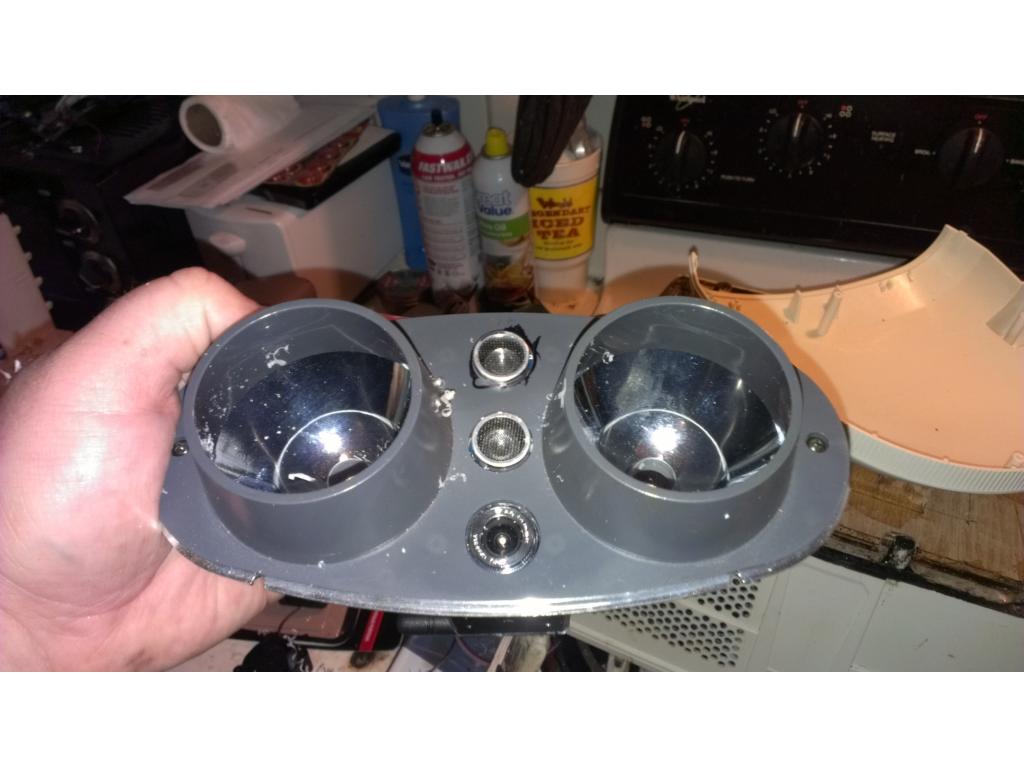
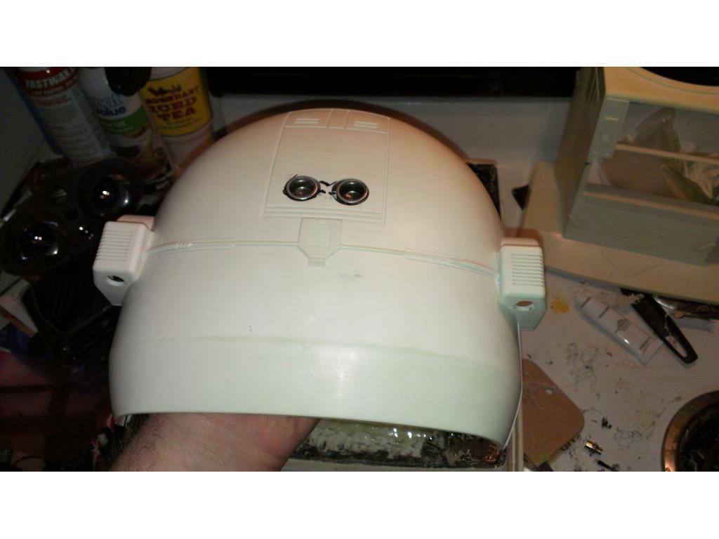
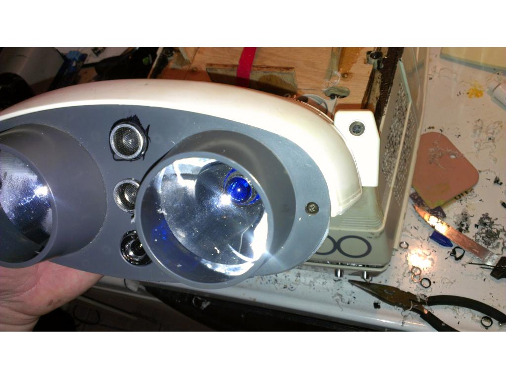
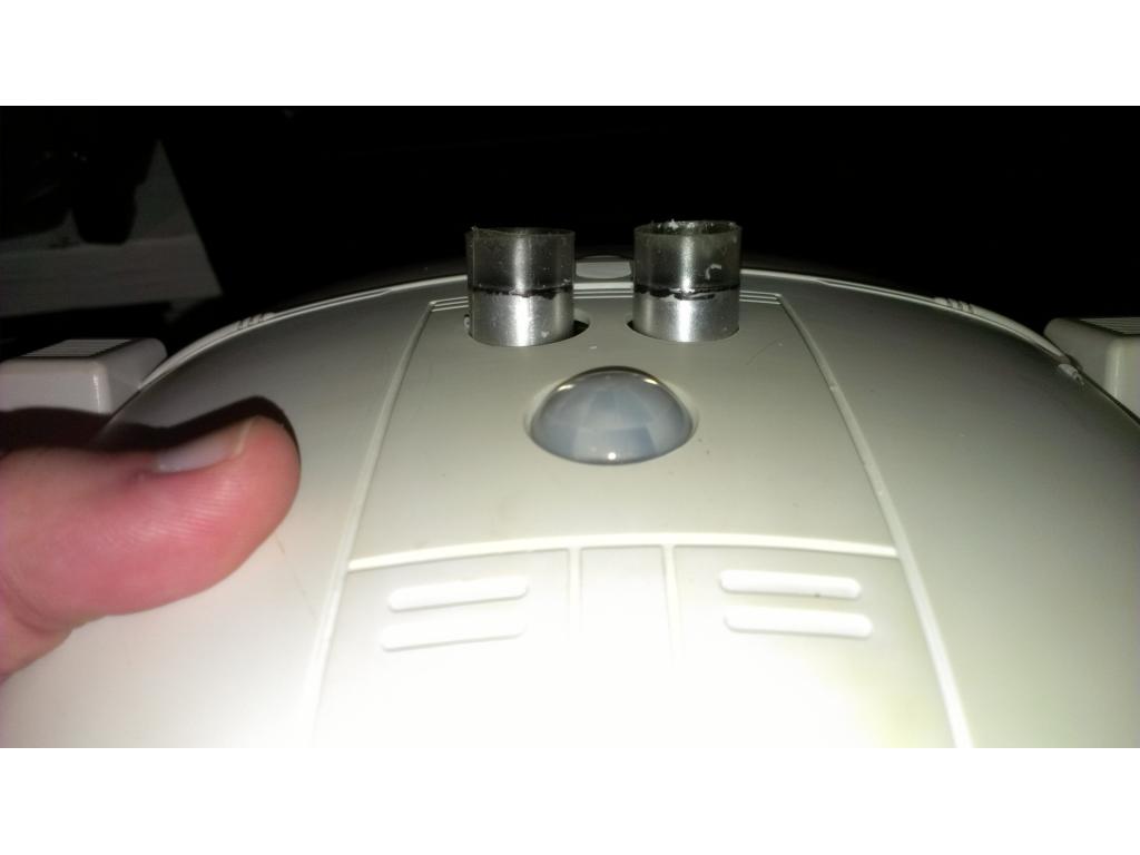
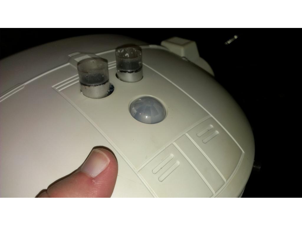
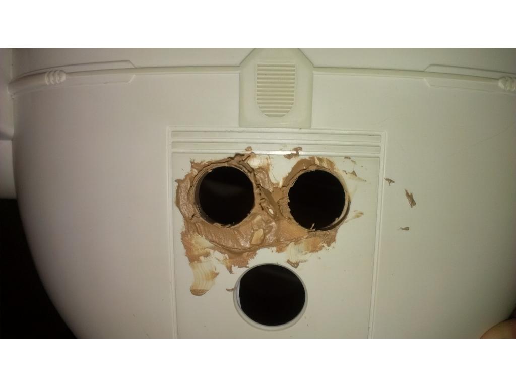
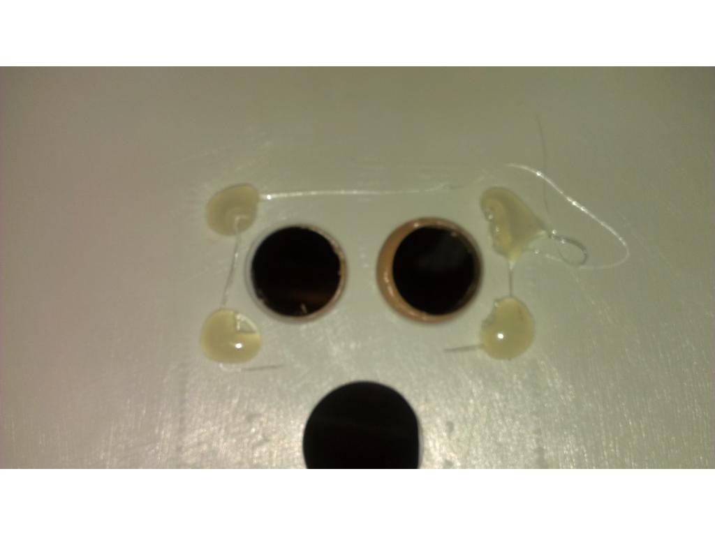
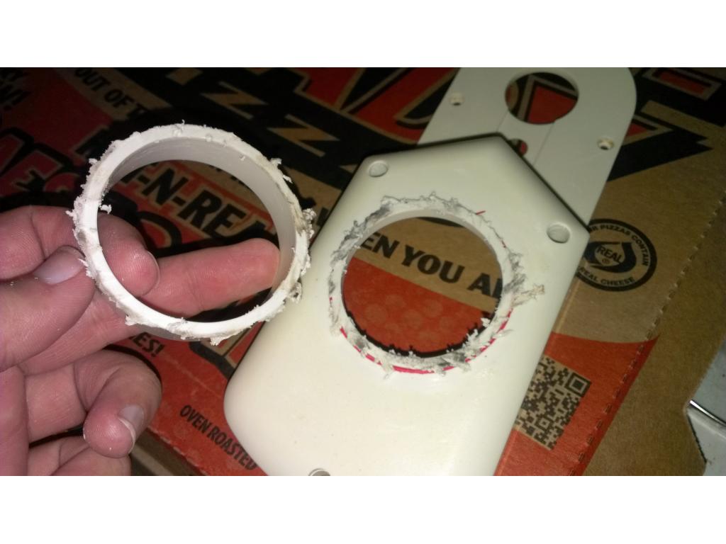
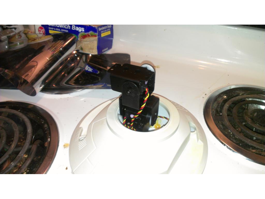
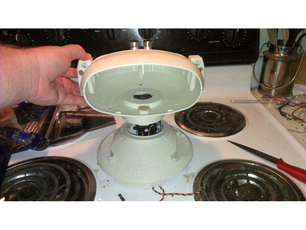
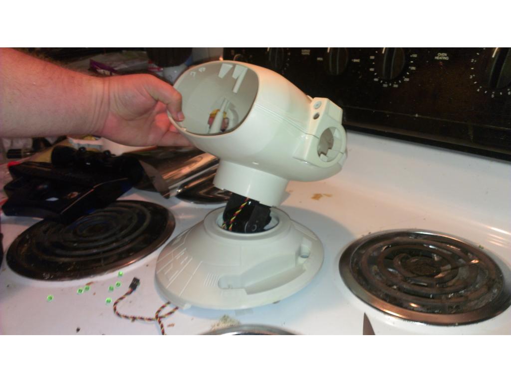
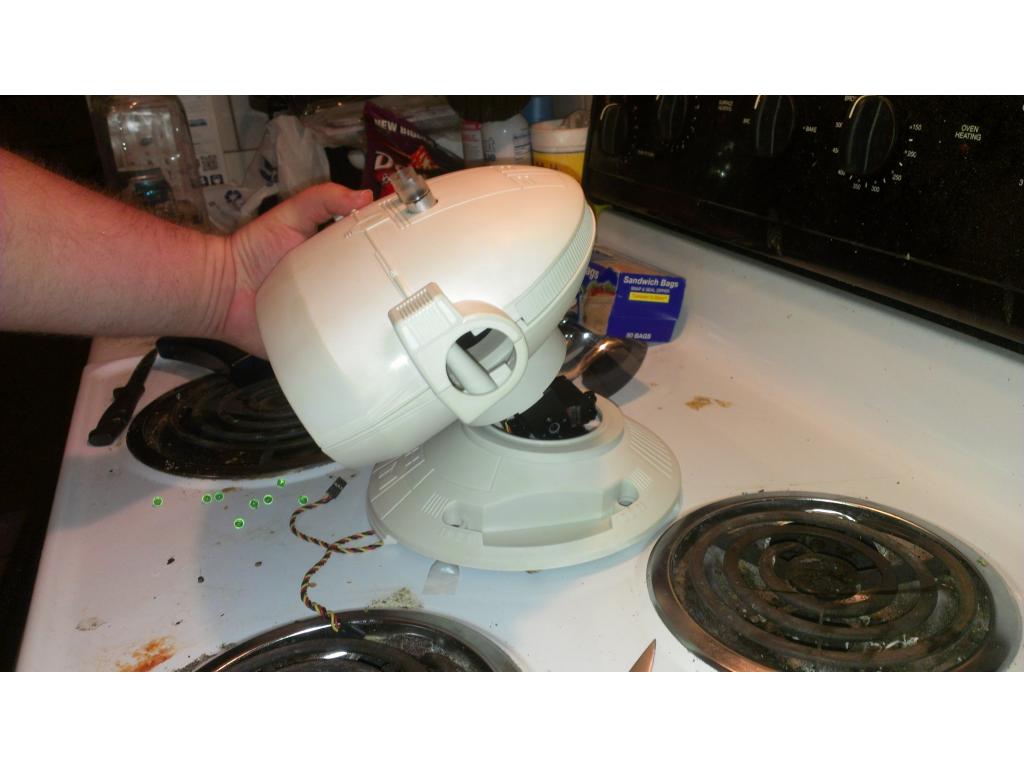
Ok I took off modding for a week because I changed to nightshift , however I may actually work.on the bot from my desk lol. I modified the camera housing by cutting a notch into each edge to clear the reflector lenses in the eyes. I used a hole cutting bit to make a perfect hole between the eyes to mount my camera. I drilled a smaller hole below the usb charger so I can do the 5v camera power mod. I used epoxy to adhere the camera casing to the inside and camera pressure fits in just like it originally did.
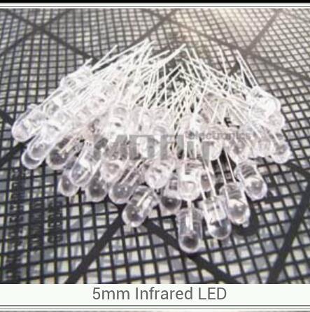
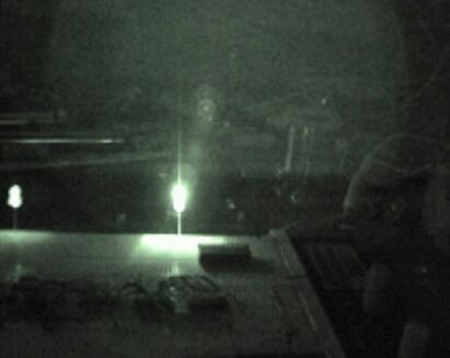
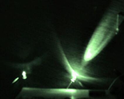
Ok the camera is mounted , I will probably do LEDs in the eyes but I am still thinking of putting a few IR LEDs in the eye sockets for additional illumination.
Nice job! You could mount IR LED's over the eyes to look like eyebrows and keep the regular LED's for eyes. Just a thought.
I'm glad you brought that up, I thought about making eyebrows from LEDs to give him more personality. Maybe even make it where certain LEDs turn on for one mood or another.
You could use the RGB color changing LED's and get three different moods from one source. I believe they change color depending on the voltage so that might be a nice way to do it.
Could you link me to this?
Ebay Link
or these:
Ebay Linky
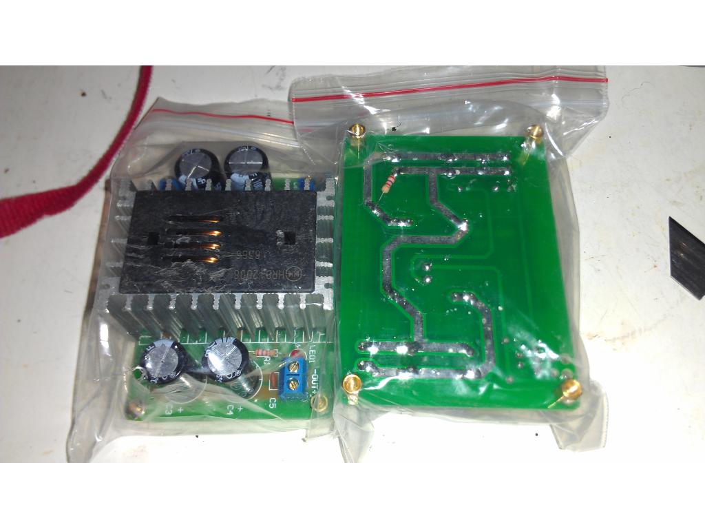
@jstarne and others i designed h-bridge design and pcb boards all info in zip file,made this design awhile back and sold many boards if anyone needs to buy the boards let me know,more that buy the boards the lower the cost to have it made ,boards are in 2 parts ,main reason is that the board is universal logic circuit on one board and pwm h-bridge on another rated at 60 amp cont,but you can easy remove mosfets to save money,remove 4 of the 8 mosfets give you 30 amps i dont get money from this and dont need it HBRIDGE.zip files in bmp and sch
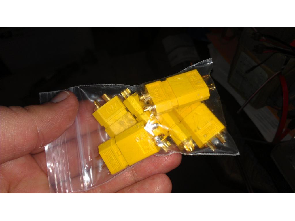
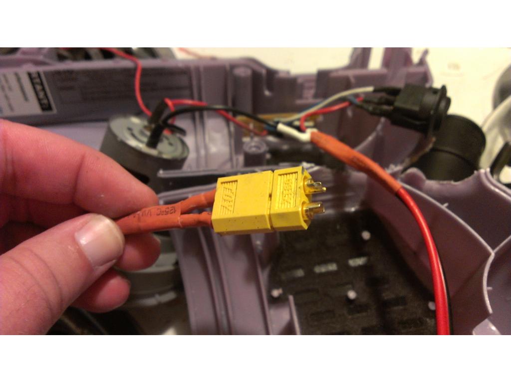
Ok time to do all the tedious wiring to the 9 different boards , pc 12 cooling fans , batteries , switches and camera 5v mod. First I was worried about arching accross my connections from the batteries. I soldered the clips on , heatshrink over them and I'm using turnigy quick disconnects. In the future ill move to lithium ion which turnigy uses these same high amp plugs.
turnigy lithium ion i use alot great batteries,just design a charger for it and one one gel cell rare at up to 50 amp charging and up to 24 volts ,both charging rate and voltage can be set,getting the boards in 2 weeks i like sending my boards out to be made,kinda hard at more and there different ways to do it,but most take time and now good as pcb company does it
you you need the circuit for yours can post it,do need to recheck it with the pcb i will get
jstarne nice job so far
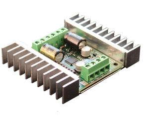
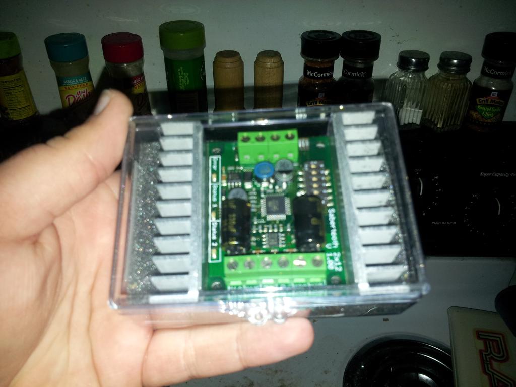
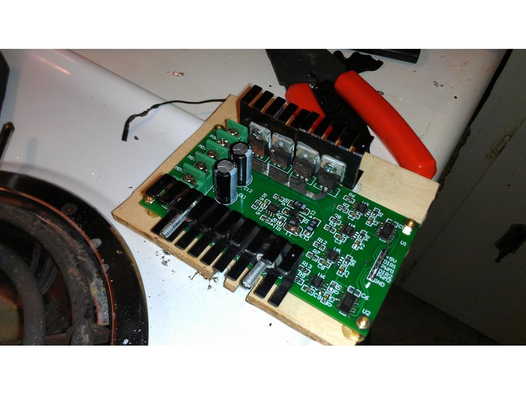
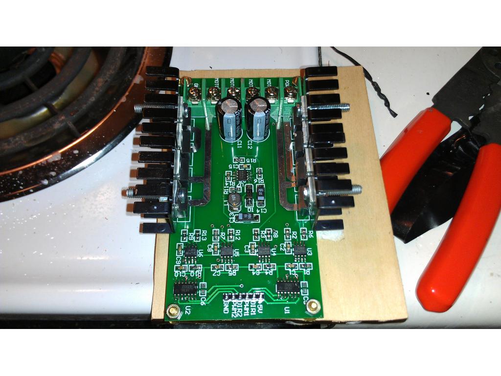
Ok here is the 10th amp motor controller , I put heatsinks on all four chips.from radioshack. This was 6 dollars retail. I just don't want these guys running hot under my boys "heavy" load. When I perform first tests after wiring I will only have one battery in the torso which.will reduce load by 6 pounds and no arms , about 3 less pounds too.
@jstarne mine is much smaller, but still very close to it,running with 20 amp load on mine the mosfets get only warm ,at 40 amp and higher they need a heatsink,looking to get my board in soon to post so far your project looking really good
also noticed they using 2 h-bridge driver ,mine is one full bridge chip and h-bridge are rated up to 180 amp and higher peak using 8 mosfets,mostly made it for very high current wheelchair motors IRF3205 mosfet are rated at 110 amps each and in parallel and quad so looking at 440 amps total each side if using only 4 mosfets looking at 40 amps at 220 amp each side maybe 90 amps peak
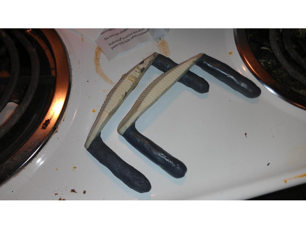
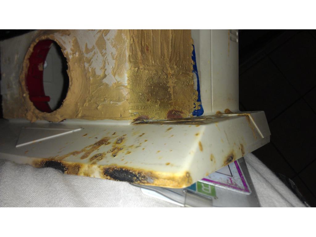
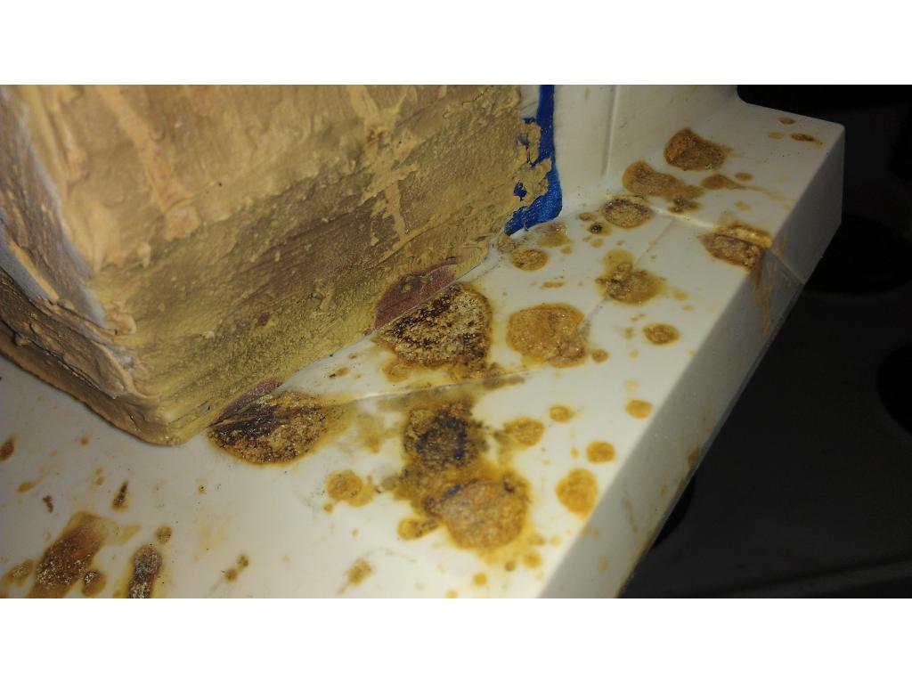
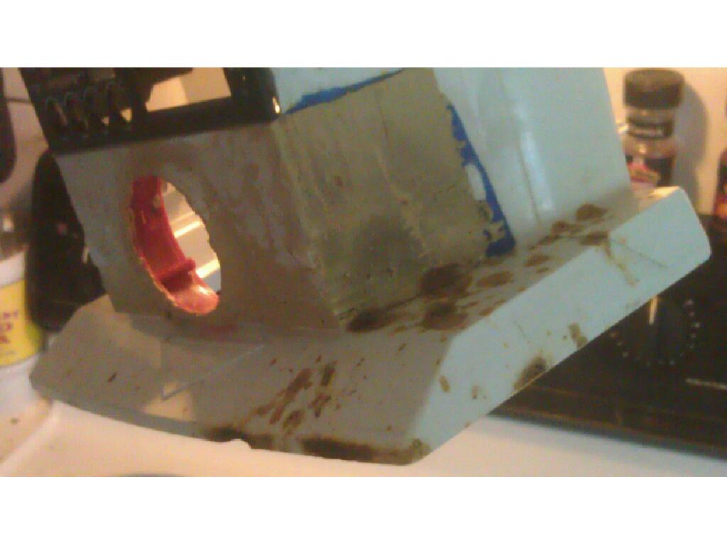
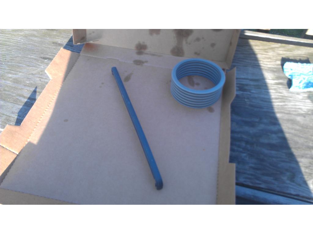
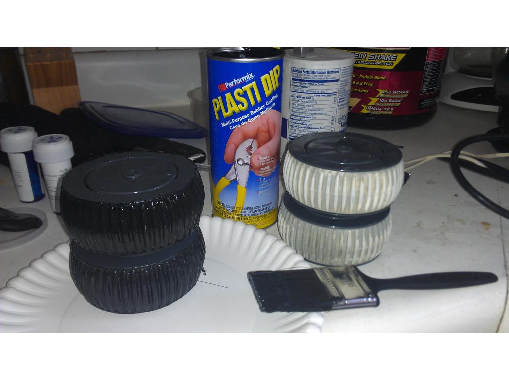
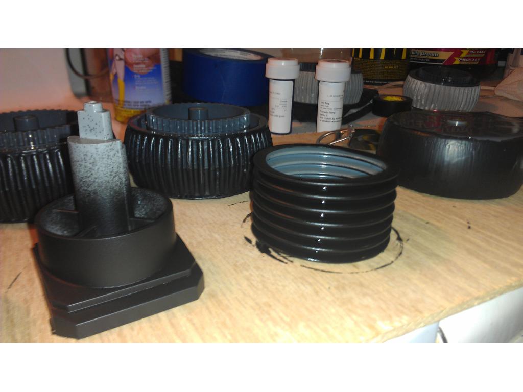
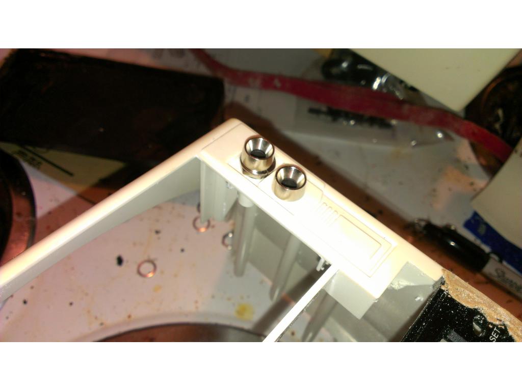
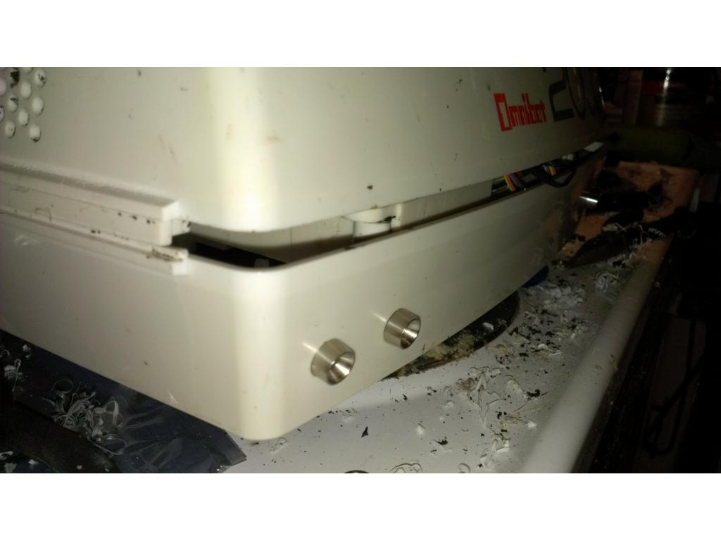
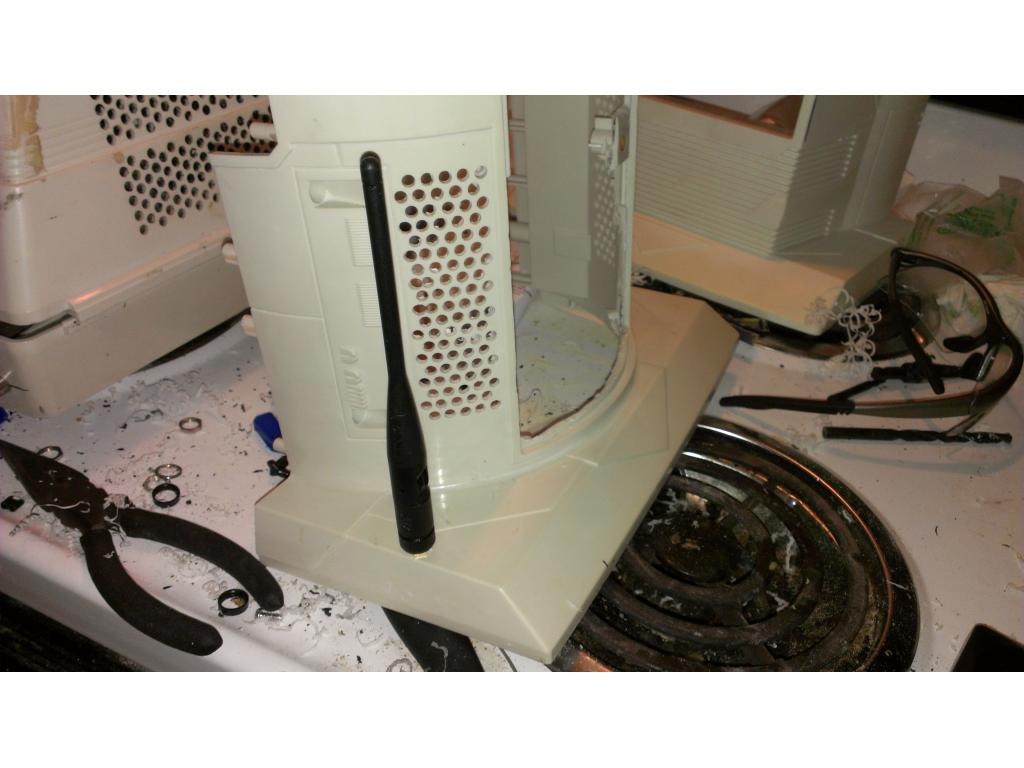
Ok today I got a sliver of metal in my eye , oh the sacrifices we make for the robot. I was wearing nice safety glasses too. So I started mounting ultrasonic stair sensors in the base. I want to bring realism to the bot and more than.the toy it was meant to be. The shoulder and neck segments are ment to mimic rubber dust boots on industrial bots. So I found some rubber tooldip to coat the neck and shoulder to make them look new yet still be flexible. More flexible than paint.

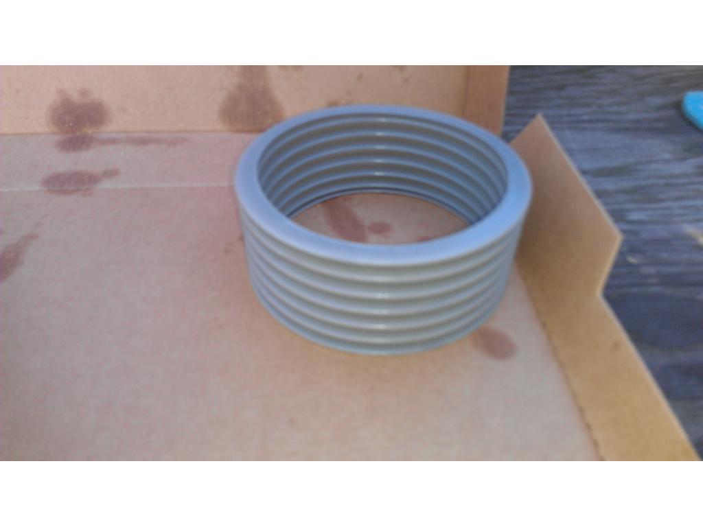
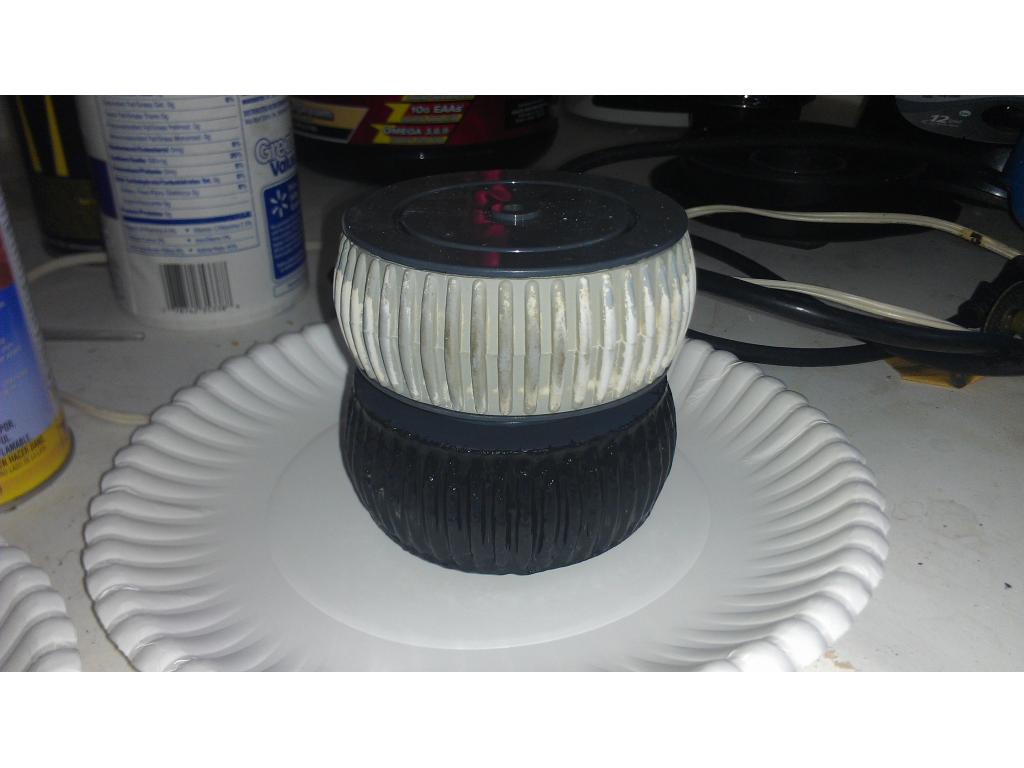
Before
First coat of tool dip...
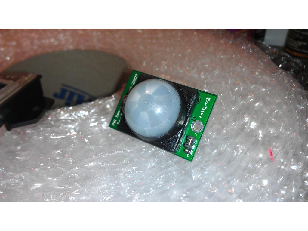
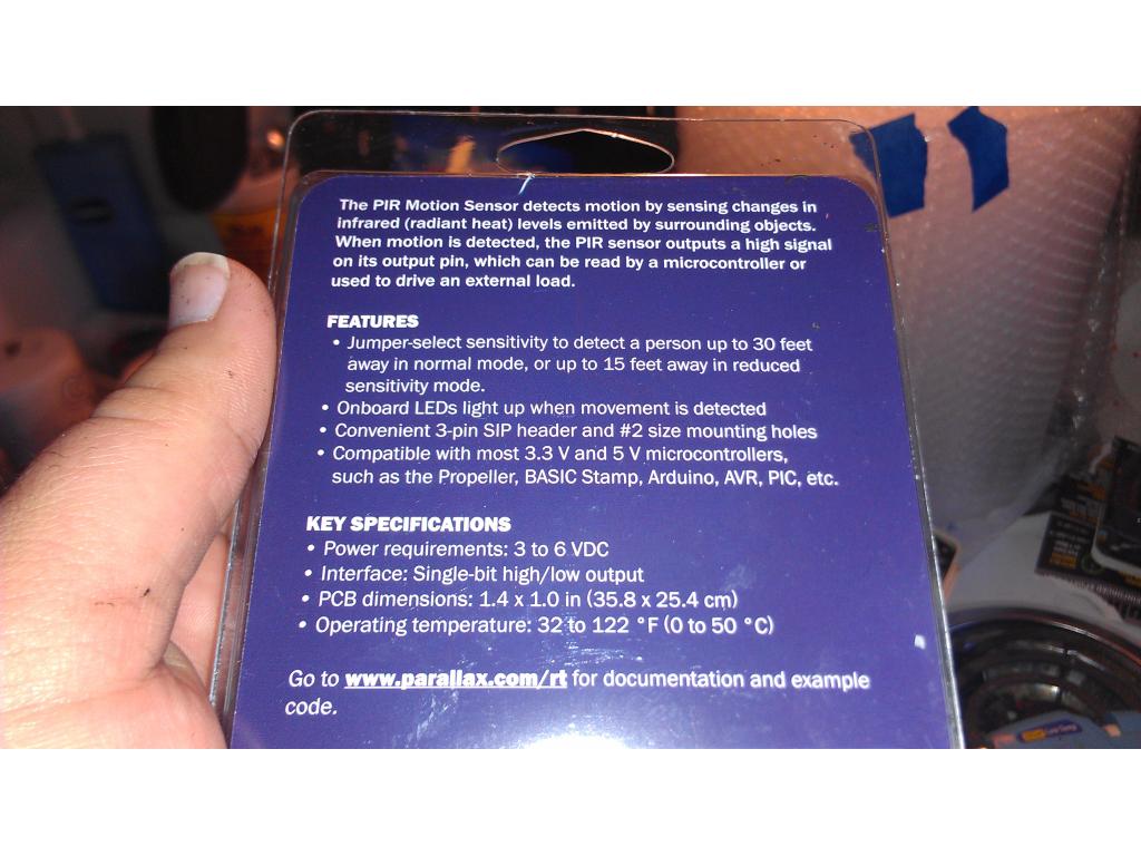
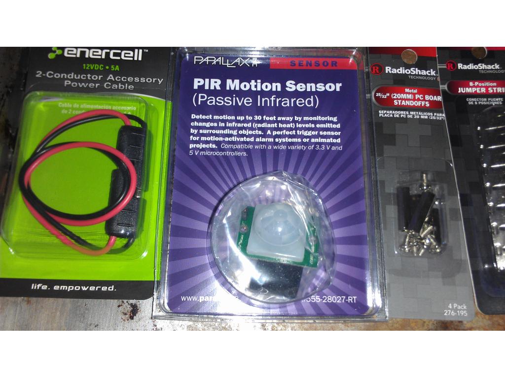
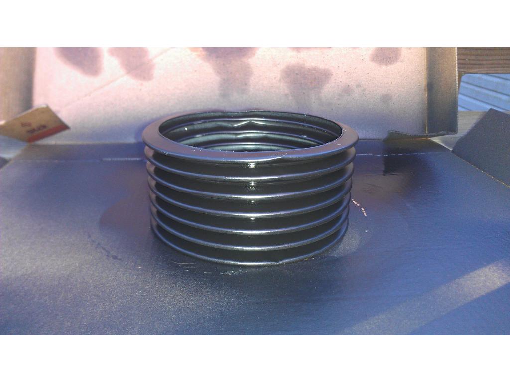
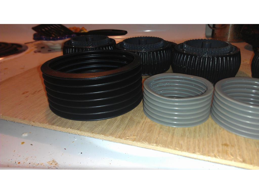
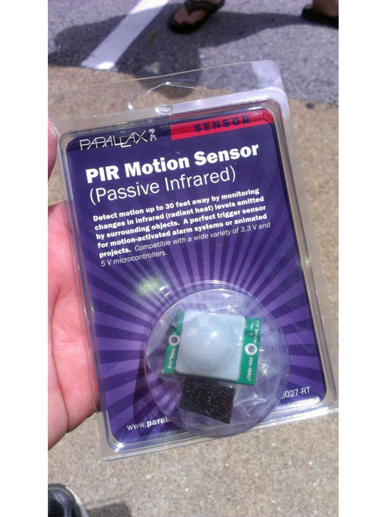
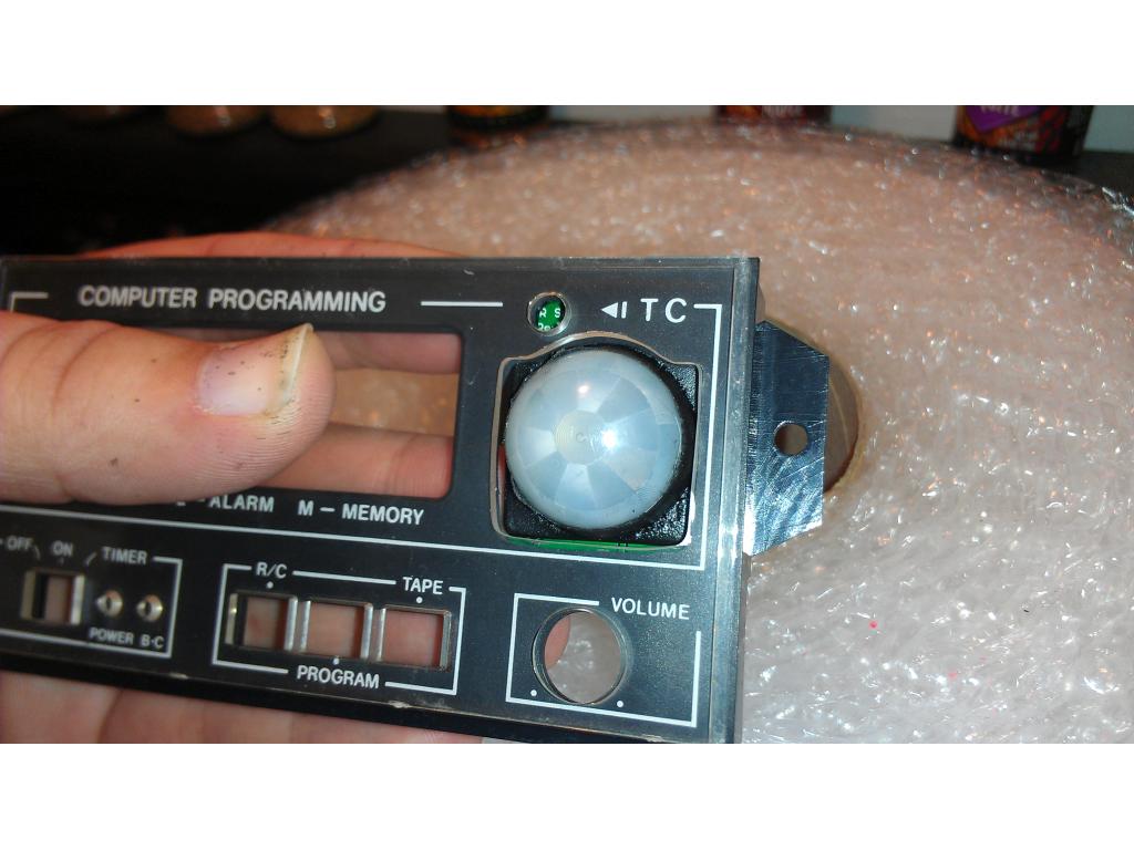
After 4th light coat it is literally starting to look like a genuine rubber boot. I believe I will spray another 2 or 3 coats on inside and outside for durability. Agian this is literally rubber so it remains flexible.I found this while in radioshack getting 5v regular low Mcd blue LEDs for eyes or indicators. I'm still thinking about using a multicolor .) Thanks for planting that idea Brett , lol my budget just went a tiny bit higher lol. It's a passive infrared sensor. Package says its sensativity is adjustable from 15 ft to 30ft+ it was just 9 dollars so I picked it up. Any ideas where I should / could mount it? I saw others use it to trigger thirty bot to "look" in that direction if it sees motion. Ideas for its use are appreciated.
looks good so far,i got a tiny spec in my once once,like the smoothie drink you made,i make one aday very heathly,have 2 special machines for them ,plus i am baker well leaving on my work trip to CHINA ,i got a new handheld digital/analog o-scope given to me by work to keep and use on my trip,cant wait to use it @JSTARNE have you look at my ROVER project on the really good PIR detectors ,very very small for $15,many different types digital and analog output,just drill a small hole
second item whats the name of the developer cleaner and whitener you used (make of it) look on sally's and they have too many and dont wont the wrong one
@jstarne1 - I have the same sensor haha. I am going to use it as part of my intruder alert system. For something like that, a good place might be the top center of his head. I guess it kind of depends what you want to do with it. You could put it on the front chest somewhere so when someone walks by he says something or acts out a script you have written. HMMMM - ideas, ideas.
@robotmaker could you.link me to these , where to buy? Thanks
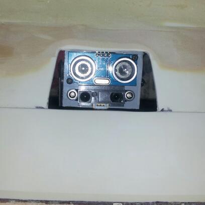
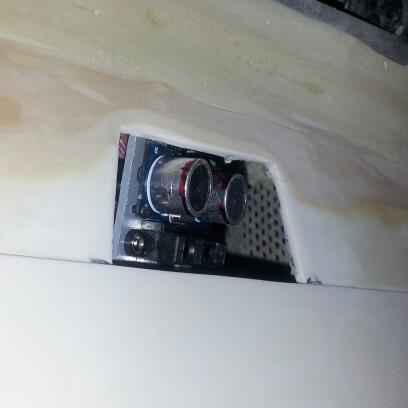
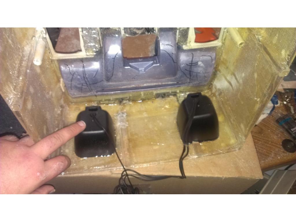
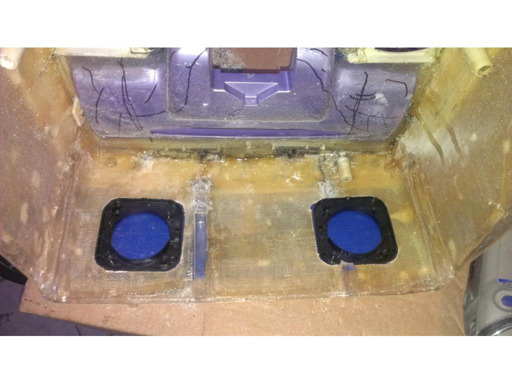
Ok now for stair avoidance system! I descided to use ultrasonic sensors because they work in most types of floors and stairs. Basically the idea we are using here is if the sensors read more than say... 15 cm then the bot "sees" a dropoff which indicates stairs or edge of table. I thought about having one sensor.beside each wheel what does everyone else think?....

The rear backup stairs sensor
Front sensor from.inside
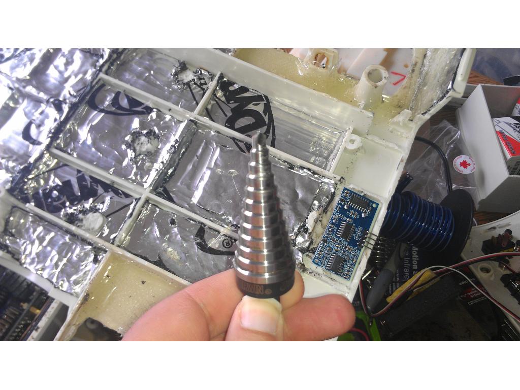
A unibit works great for sizing out the perfect hole for discrete mounting positions.@jstarne here is is buddy,like the uni-bit,i have all 3 of them ,they great for robot projects
what about the developer you used what name or it or link motion sensor they have others on digi-key site
utrasonic not great as stairs detectors,one main reason false or bad reading if any carpets,mostly all people that build robots and companies use IR sensors short distance types
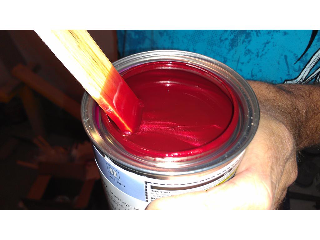
Hi guys , I know this is still a few days away but its getting close to paint prep time. I want to go with a really nice red but a OEM color that's easy to match in the future. I'm going to look at cars tonight a little bit. If you have a idea for a red similar to iron man red please post pic , model and year and paint code if you find it. Thanks guys!
Depending on what pictures and lighting you see pictures of iron man in you might like Barcelona red by Toyota. It does have a little metallic in it though so I'm not sure if it would be easy or difficult to get matched later on. My tacoma is a 2009 painted Barcelona red and I know they still paint cars in that color. Should be easy to find and look at. It would be cool to use a candy apple red however it'd most likely be a huge pain in the butt
Yea my painter said a candy red which is base , then color , then 5 coats candy and clear would run me 200 for the bot parts. I'm gonna find a pic of that and post it.
That is HOT!!!!! Here is a pic of my car, the color is GM Crystal Red. It is a deeper red out of direct sunlight.
Sweet , Bret on your doorjam or a sticker on the bottom side of your hood there should be a paint code. That's a great color too
Paint reference for gm looks like I'm getting crystal red! http://paintref.com/cgi-bin/colorcodedisplay.cgi?type=sample&ditzler=915635&syear=2009&smanuf=GM&smodel=Corvette&sname=Crystal%20Red&name=corvette2009WA505Q
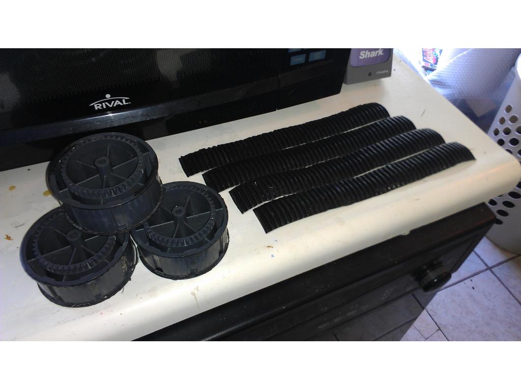
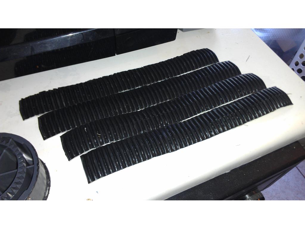
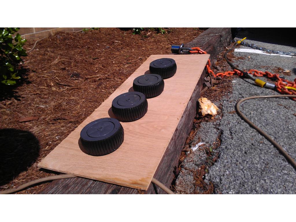
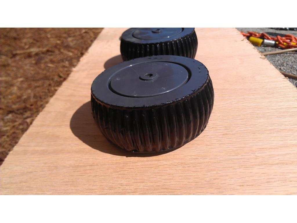
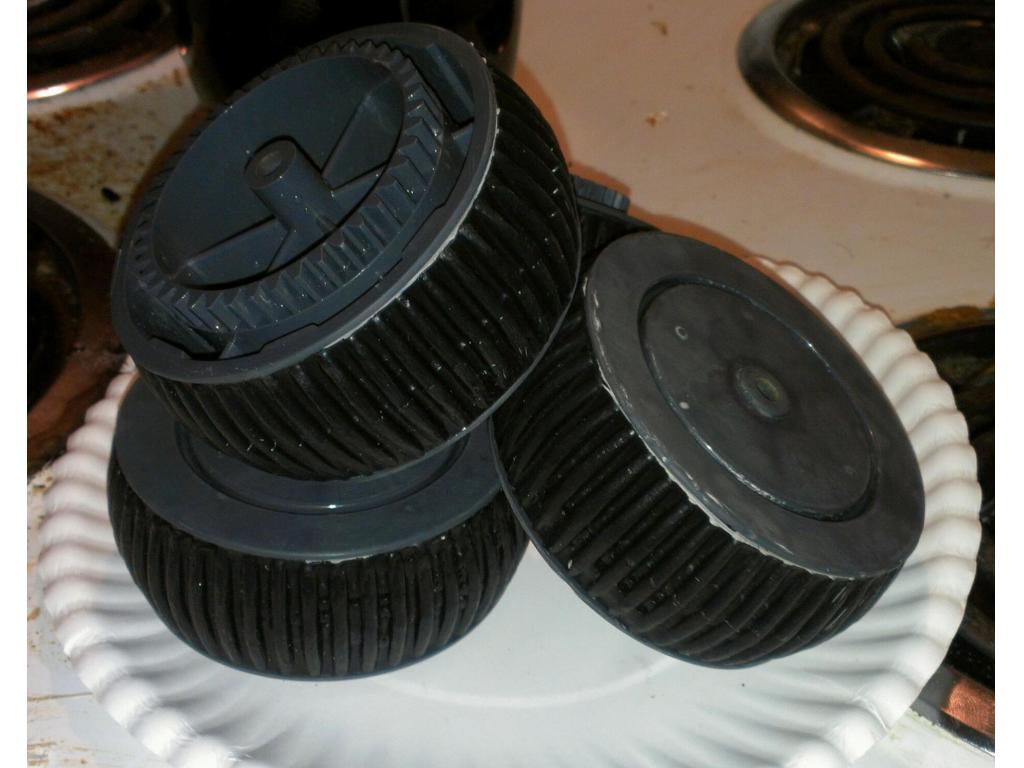
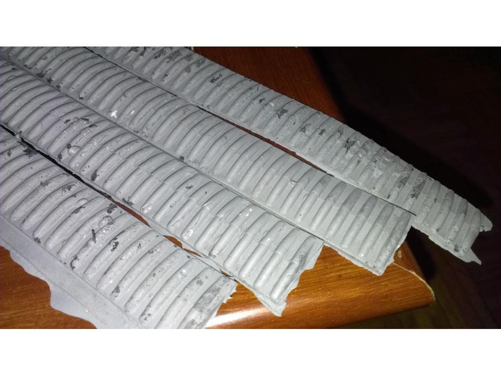
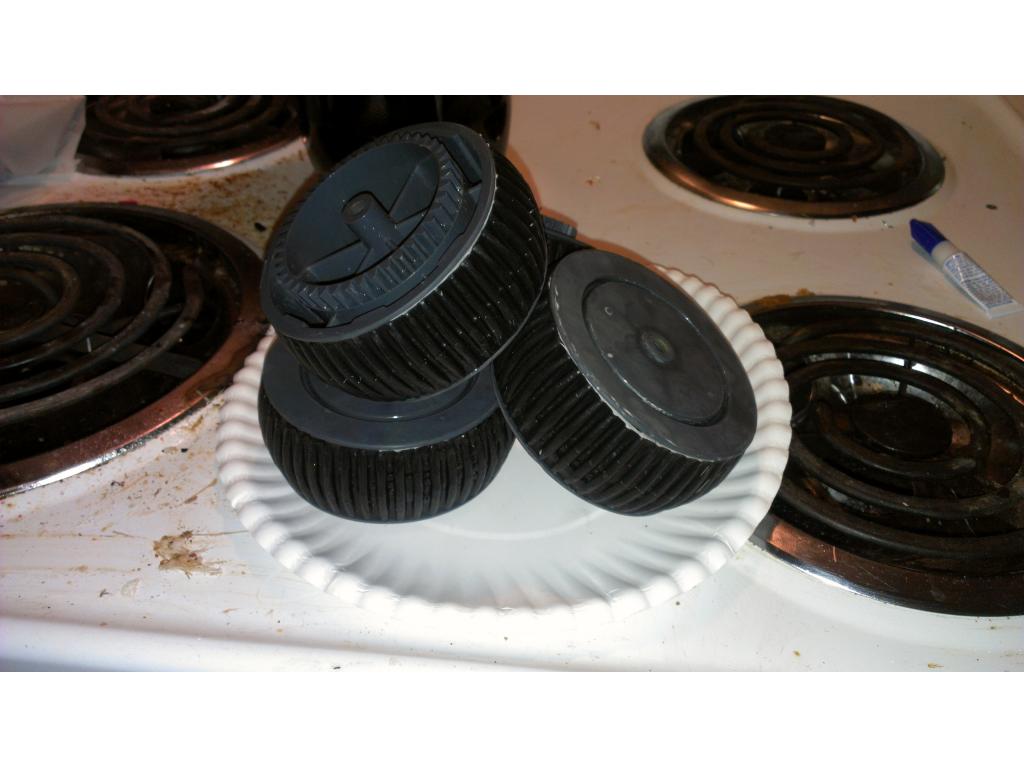
Ok buying paint tommorow but for now I gotta take care of suspension on this bot. These tires are old and could use some retreading. I picked two plastic rubber coating products. First is tool dip for heavy duty applications and spray tool dip for places I need extra thin coats like robots neck and shoulders in plain view. I used a paint brush to apply tool dip liquid rubber over the original 27 year old treads so this new rubber would maintain a original tread pattern.

After two thin coats , let them sit outside to cure , if you need a touchup wait till its cured 2 to 4 hours first.Nice Idea! I like it.
Ok I tested this paint on rubber and its a alternative for areas with lots of nooks and crannies that's hard to.get a flat piece into. This coating is safe and completely non conductive. Spray rubber works too I just noticed it goes on.thinner for each.coat and costs more in a spray can.
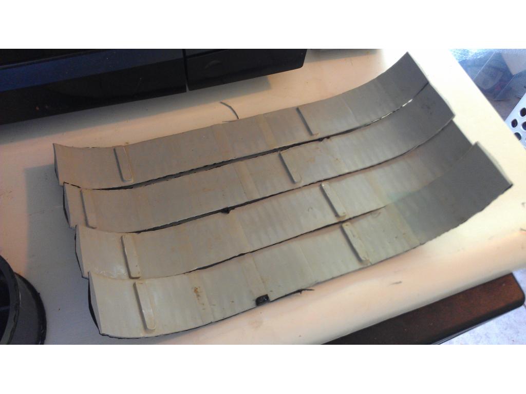
Ok I took the shoulder skirts off and washed them well. Here's the neck skirt next to freshly cleaned shoulder skirt. Soon as it dries it will get a coating inside and out of rubber to match the neck. Also I will coat the rear dummy wheels as well.
Ok I have a couple coats on the shoulder pieces , just a couple more coats inside and out once this dries.
all this work and only vacuum the floors,looks good
I'm sure it will do.lots more. It will be my personal computer , a security bot , feed my dog at a certain time when I'm at work and hopefully I can teach.this guy to bring me a beer too lol. I want.it to fit in and be good looking like a high dollar appliance. I may install a screen on the front so its also a telepresence robot as well.
looking at the same with my omnibot,my full size robot will have arms and full hands,main reason for lathe machine,but add my AI LEAF project to it ,and mostly all my robots have you check the LEAF project,only full AI design project open source there is so far,fulll emotions, and chats,recognizes faces ,objects,spells and so much much more i finished a design to detect beer from water or milk called spectrometer
Can this leaf thing.be used with ezb? Easily?
Ok back to work.. I been pondering the power system because the bot must be able to charge. I descided to wire it similar to a car with 12v system that charges between 13.8 - 14.4v my regulated power supply is 12v but I believe I can adjust it in high 13 volt area otherwise I would need to get a nicer power supply. In a car the battery is always in the charging loop so when my bot docks for charging its completely uninterrupted. Everyone please look over this. Also just to let everyone know all the juice passes through the LCD system monitor wether it comes from batt or the ac adapter.
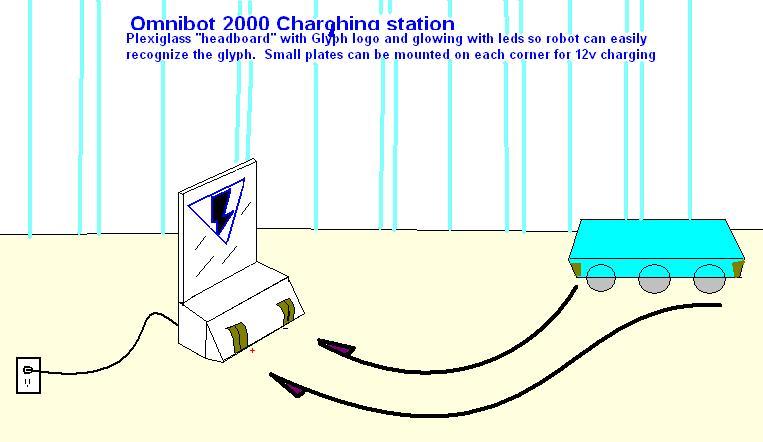
Potential docking station. , just an example not a final idea or design...
dont you have a led system monitor not lcd,each led near 20 ma x 7 segments so you are looking at alot of wasted current draw,lcd monitors are cheap and easy to use and very low current
Holy cow! eek That is one seriously awesome robot! What excellent work, that definitly is looking like a high dollar robot. You must have put a lot of time and $$ into it. I am absolutly impressed, that is so cool and very inspiring. Awesome!
@okidey I probably have 1000 , 180 was for computer, 70 hd, 40 ram and 90 for CPU, 235 for ezb , 200 for nice Omnibot 2000 , 40 for all the cooling fans , 30 for H bridge , 15 wiring , 20 for 2 12v batteries , 25 for 12v 15a ac adapter. So adding that in my head was 925. It's also getting a automotive quality paint job gm crystal red code 89 which after paint costs and paying a buddy a few bucks to paint it is 200. Wow building a nice robot has a price , I haven't really thought of how much I spent. Thankyou for the compliment it really makes my day. This is my first robot build.
@robotmaker the LCD is not only for systems monitor but its built into chest of Omnibot where the factory LCD was. It's draws about .2 amps
@jstarne on the led units i was talking about are the dc-dc converters you are using 3 of about bout the right price for a good design,mine mostly over $2000 my big big project JOHNNY FIVE LIKE SIZE will be over $6000 MAYBE MORE here is the link to it,tracks and motors alone are $500 each one the we bsite so far they dont have a computer, just base plans , mine with have LEAF project,still looking for a SAPI voice of johnny five
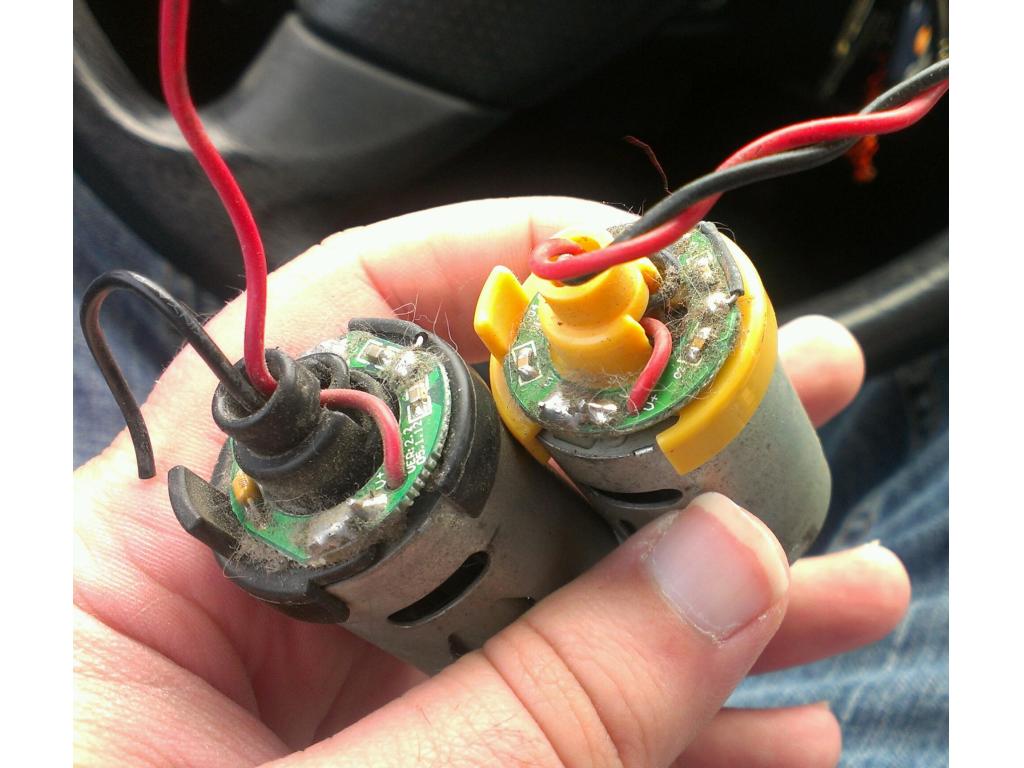
@robot maker. Johnny 5 voice was human voice recorded with autotune. You could maybe make your own mp3 files this way adjust autotune and pitch till you sound like Johnny 5 . I would love to make him , or.the newer robot from lost.in.space movie. Lastly the robot from evolver would be a menacing security droid. Anyways I will get different dc to dc regulators with higher 5-10 amp current handling without the LEDs on them because eventually all the motors in both my motorized arms will be functional and 2 amps won't cut it. Next payday I'm buying three h bridges to power the original motorized arms. , and those could draw 2amp each depending on load. Right now I'm trying to find motor replacements for my motorized arm as they are corroded and locked up. They are 3 or 6v motors....
If anyone could help me find a direct replacement that could run 6 to 12v I would greatly appreciate it!
from what i can tell they look like the stock motors in the rad main drive i new the 2 amp dc-dc converters wont work,but good for sensors ,EZB and rest of low current stuff on the voice its TIM BLANEY AND AUTOTUNE most R2-D2 builders buy parts a little at a time pre-fab parts,SOME ON EBAY rest custom made some parts i got or made ,like his eyes and iris same on johnny five,iris i think i paid $35 each at edmund optics,stereo camera $200,led vu meter for his lips moving,made part of the telesccope RF controller (multi-frequency controller) on his head
also the stock rad MOTORS i dont really need,so can sell cheap
@jstarne1 - how many of those motors do you need? I have a few from my RAD torso that I won't be using if they will fit. You can have them dude. Just let me know if they will work.
I need three at least. I accidentally washed one.motorized arm in.dish washer and all the motors are.locked. so three , two a minimum for claw and.wrist movement.
@ jstarne1
You are very welcome! It is very inspiring to see your robot, things quickly cost a lot of $$ but when passionate in making something the results are priceless right? I do not have the knowledge nor a lot of money to make a robot with all the hardware you have working on it on yours. Though I am completly new and just started out building robots for myself. Results like that require lots of time and effort and dedication, who knows in time mine may turn out as cool and extensive as yours, and hopefully I may learn from your experiences and everyone here. You guys make some seriously wicked robots.
I havent gotten very far with Hank v1.0 unfortunatly, though I have been working on something else which ill be showing too. I am learning and having loads of fun doing so and together it can all result in hopefully as wicked. I keep getting more and more ideas.
I am now starting to get into the software of things and I'm thinking of adding AI with the Leaf project. I will be running into a pile of questions I'm sure, aswel as hardware problems. I've been checking out all the robots made by members here and reading about it and I can learn a lot from you and all the members here. Hopefully I can share some valuable experience of my own. Im going to make pictures of what ive been working on right now, I hope you guys like it
@jstarne,i see you are mounting sonars on the bottom of your robot,do you have carpet on any of your floors, it wont detect it
They can't read carpet at all?? Should I remove these and use ir??
yes,look for short distance ones like this one should work and digital is better since you are not detecting distance only steps and ledge detection
short distance digital also these are great for non contact bumper switches you set it at 10 cm or distance to hard floor to sensor,then stay high from 10 cm or less like if see carpet or tile or wooden floor,now if you have a step it will be over 10cm and output goes low i dont know what the distance from your bottom of you robot to floor IF can tell me can find you a better one also sensor reads at 24 cm so you need to modify it ,here is the link
short distance digital modify can modify from 10cm to 24 cm ,10cm is 3.94 " and 24cm is 9.449"
another IR sensor will work is 1.5" to 20" but analog ,if you have some ports left over
short distance analog remember to set the distance from robot IR to wooden floor,so it will detect carpets ,floors,and small metal strip for carpets and any thing higher will be cliff detection
and these are great for non contact bumber switches,dont need a bumper guard like on the neato,good reason if using bumper switches robot cant turn around but with non contact IR sensor it can because you can set the distance
on IROBOT ROOMBA is uses them for cliff detection
Ok I.bought 4 of those ir sensors the 4 to 30 cm distance sensors. I may only.use two but spares are nice
http://www.junun.org/MarkIII/Info.jsp?item=37
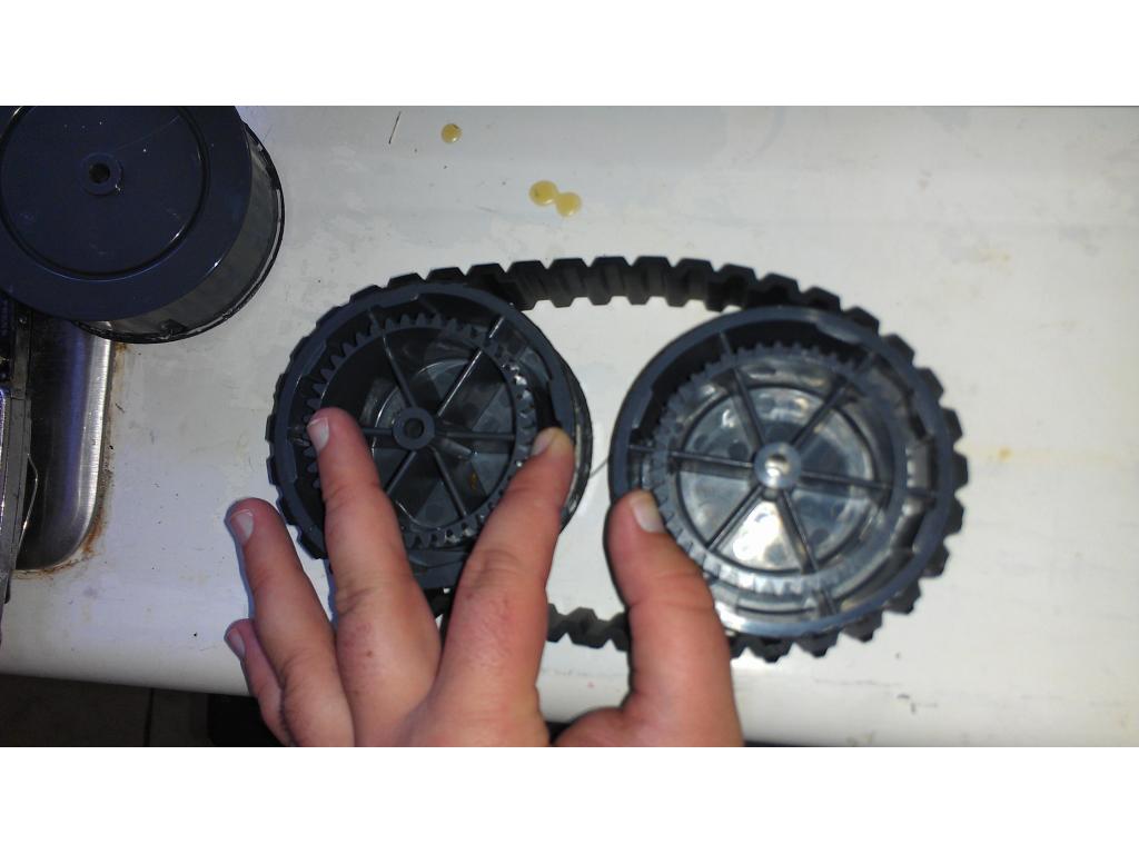
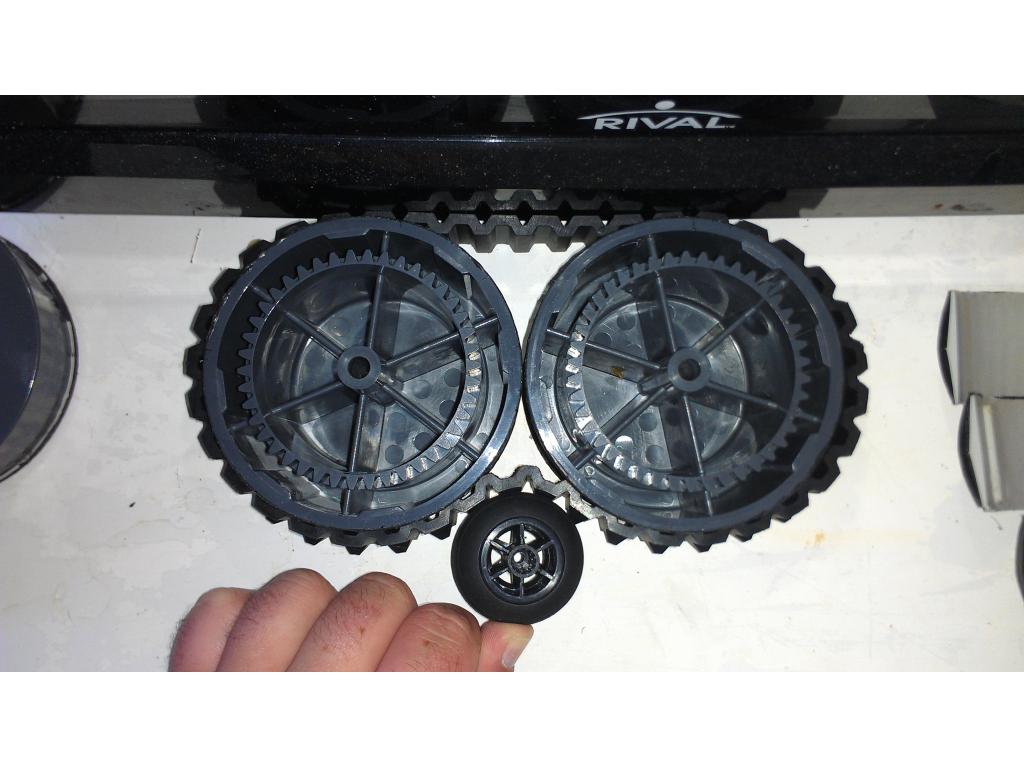
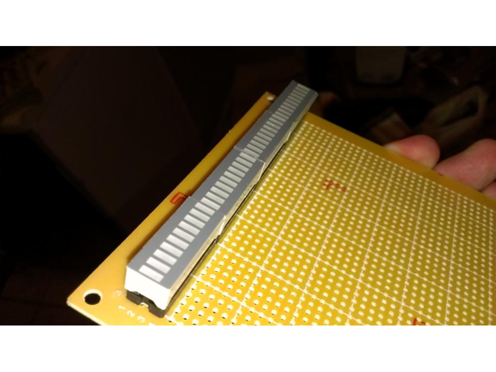
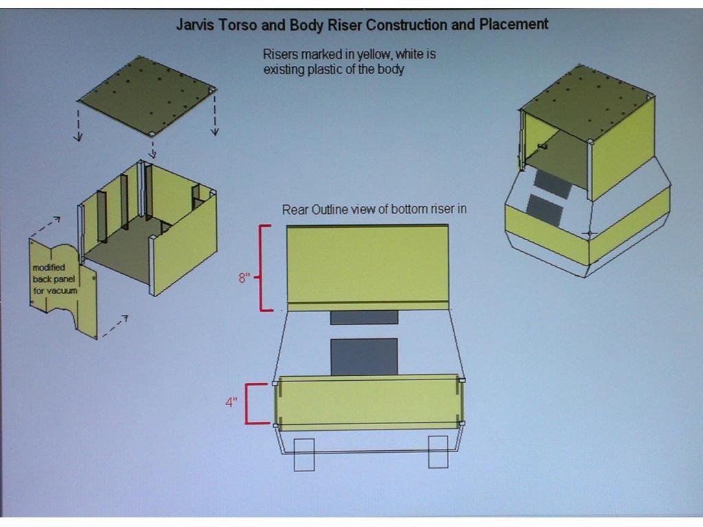
Also I descided I could try converting my bot the treads using rover 5 tracks which are 1/8 in thinner than rubber treads on omnibot 2000
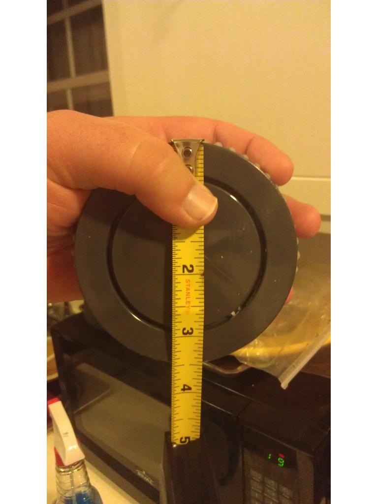
Doing.some math I.figured the length.of tracks at max stretch , using omnibot 3 inch wheels its 1.4 inches shorter so the tread should fit snug agianst the hub. Diagrams above show how I would do this. Also on the way is 2 6amp dc to dc converters to reduce drive.voltage , servo supply power and origi nal motors from 12 v
i finally got me omnibot 2000,cant wait to start on him ,its monday morning in china now,i know my girlfriend is happy,me getting it and comming home this friday,i hate the about 20 hours on the plane right now it lunch time at work,i think right now back home its 12am,food here super cheap @jstarne the tracks looks great also
wow man what do you do?
i design and build high precision in-house test equipment for A/C and electrical test company
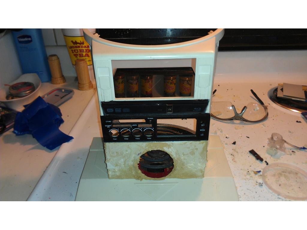
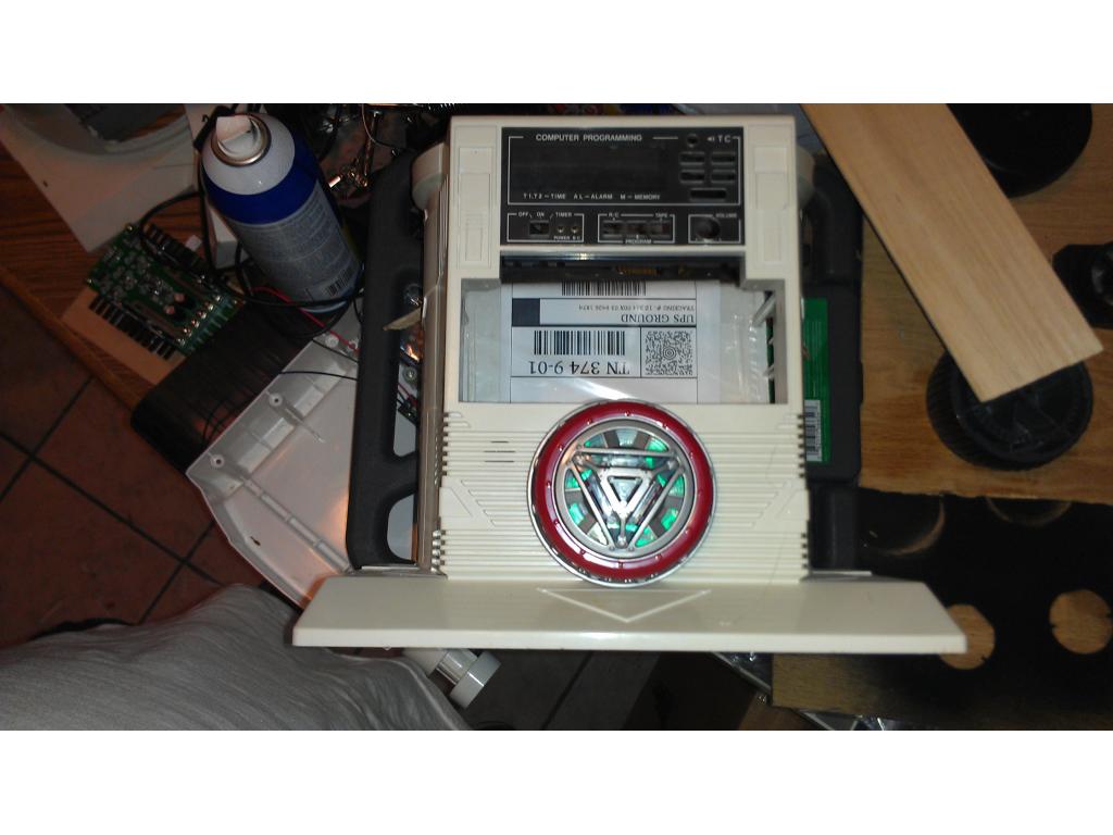
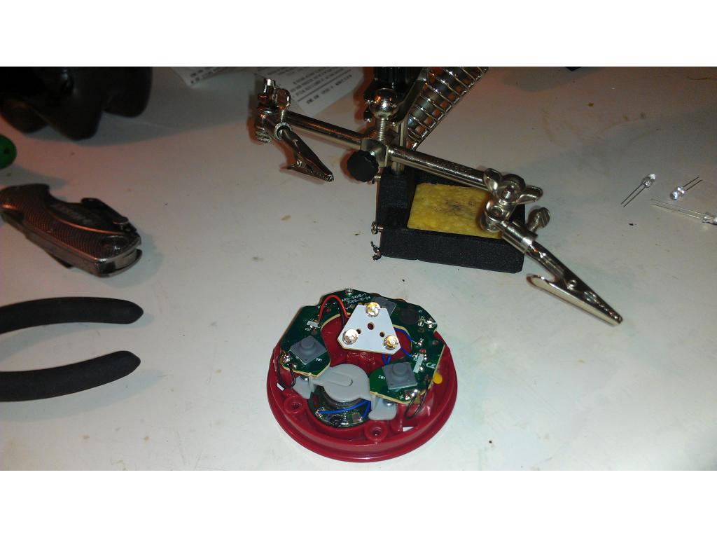
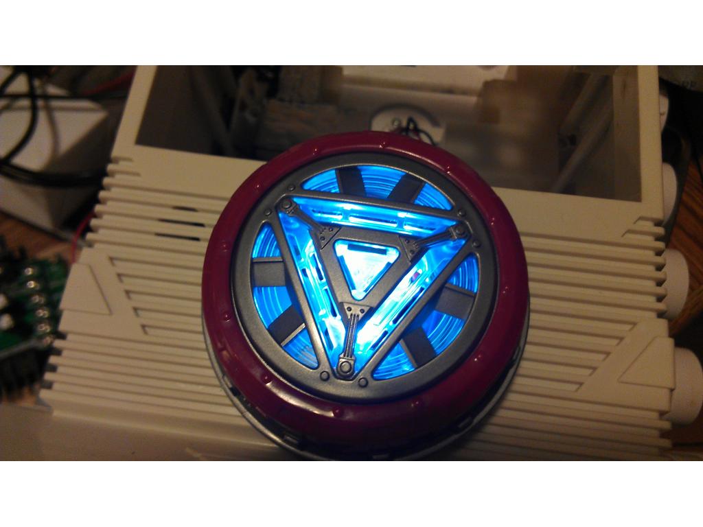
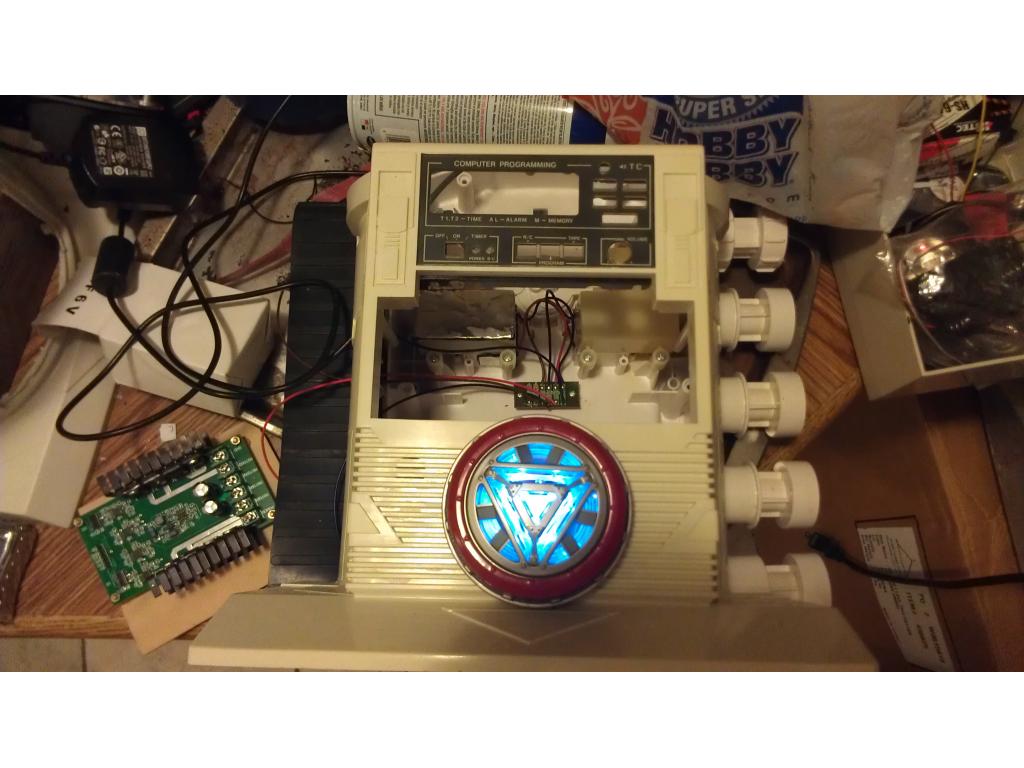
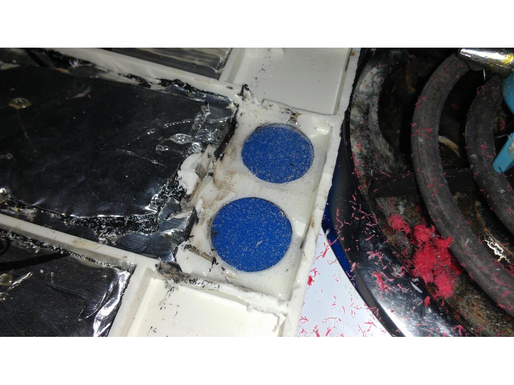
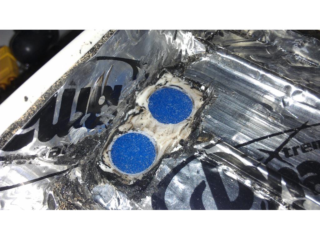
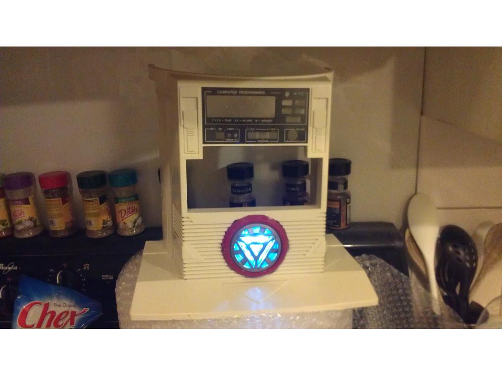
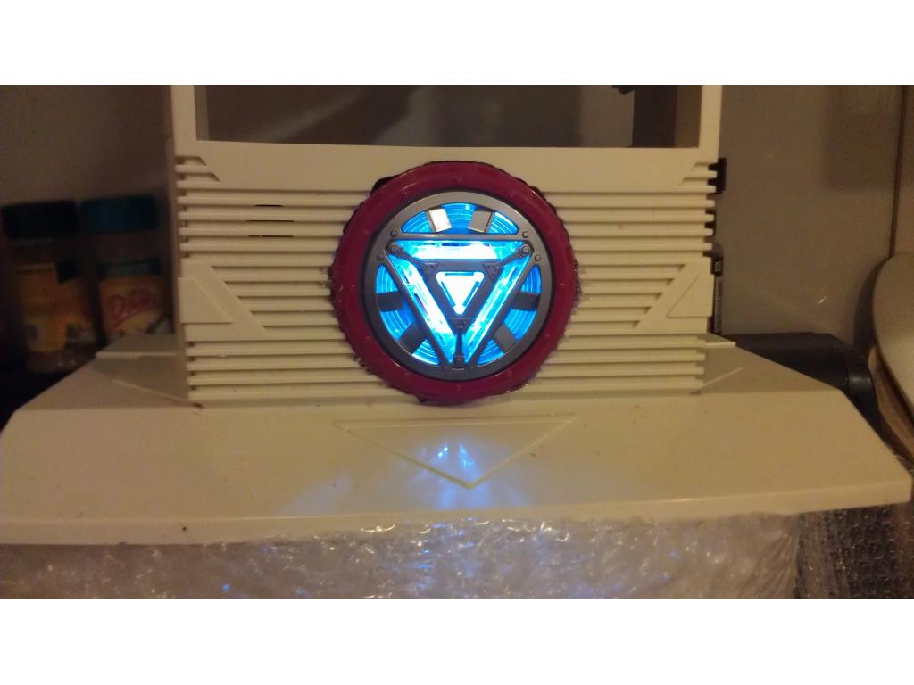
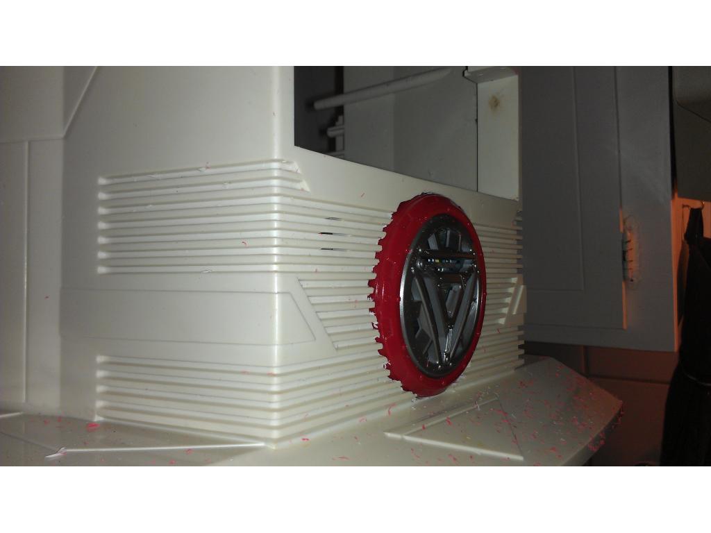
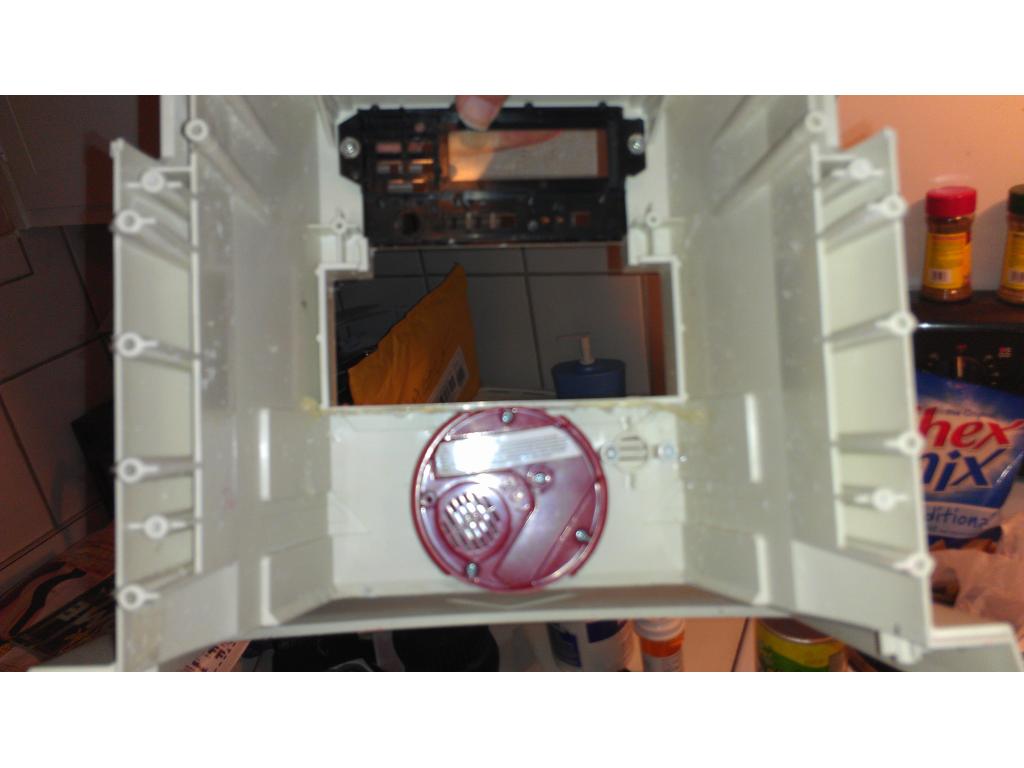
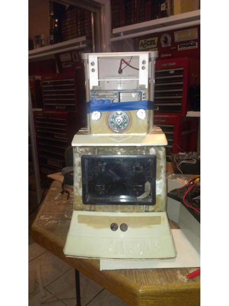
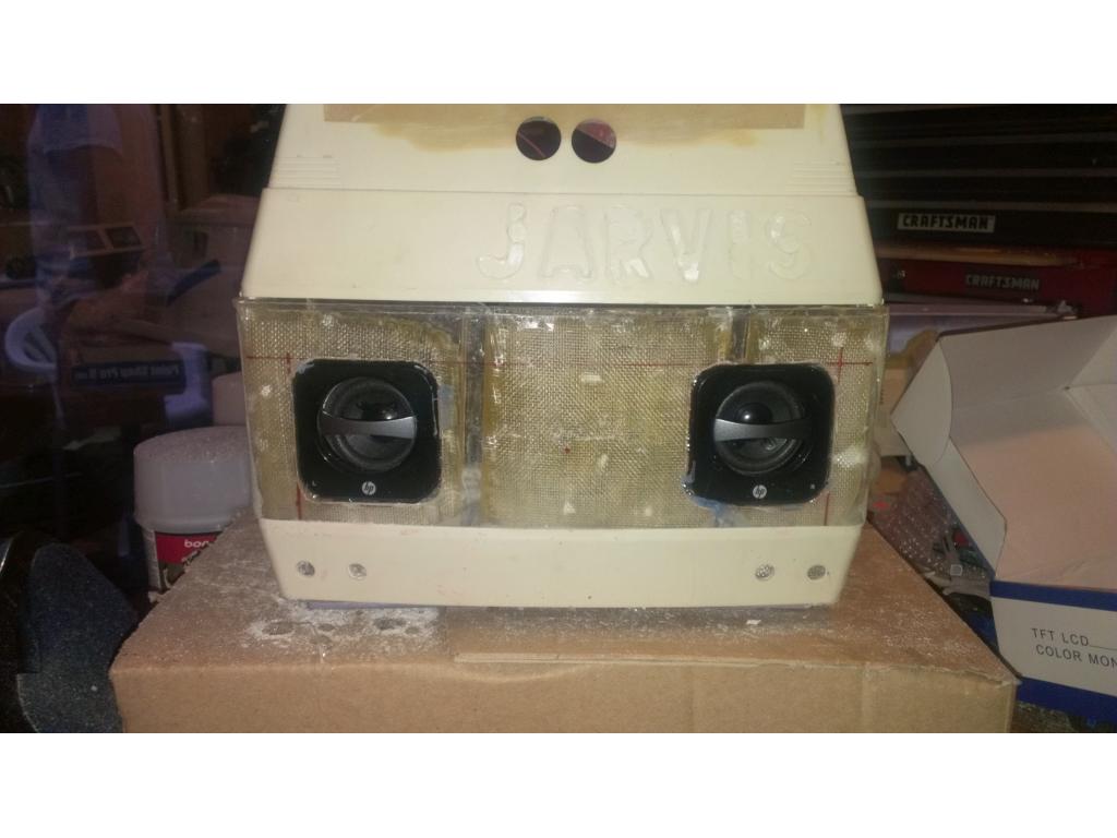
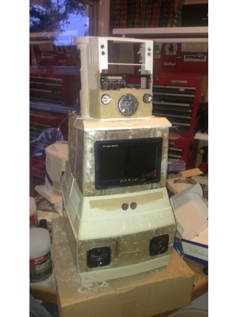
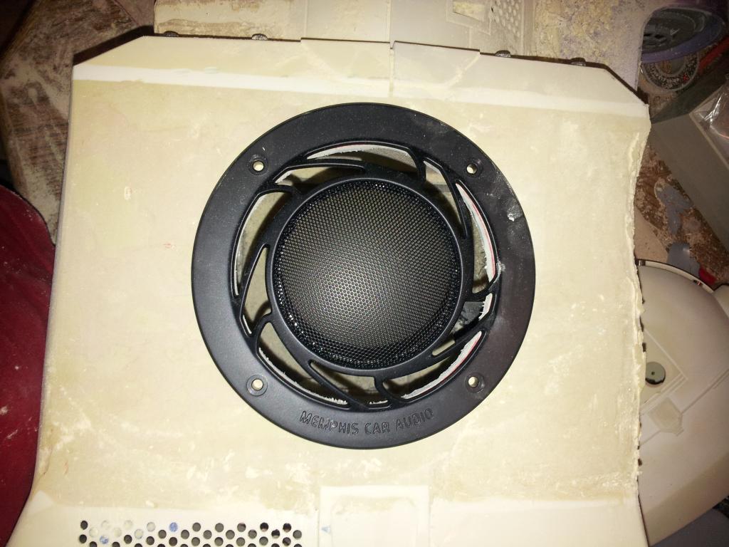
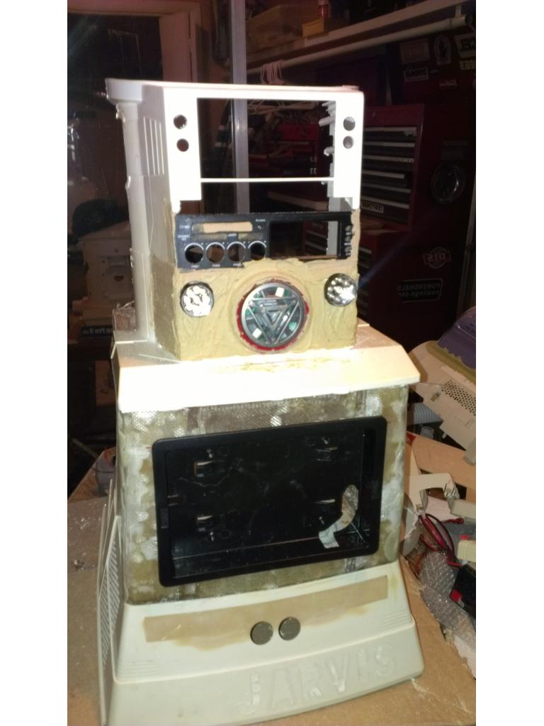
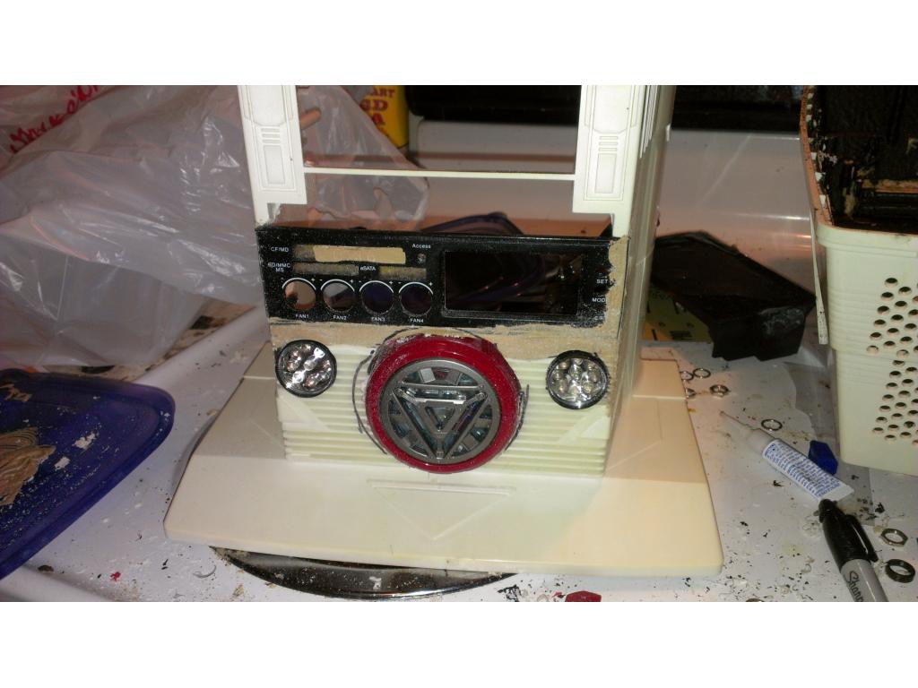
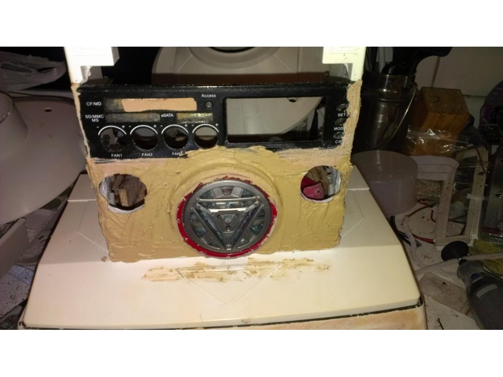
Ok so obviously I'm giving this robot a iron man theme. No better way than for this robot its very own ARC Reactor! I purchased a Hasbro toy but once I recieved it , I noticed it had a unconvincing Amber glow when lit up. I took this guy apart and installed 3 bright white LEDs. It's amazing how much blue color is in a white led. This picture just shows the toy sitting in the placement where I would like it to go. I believe I will cut into the speaker location a recess the ARC reactor in about 1/2 inch deep or more. Once it has been installed into this torso it will also be painted the same crystal red color. If anyone has additional ideas let me know .
.
instructables.com has many ironman ARC reactors.lot of them look very close to real in the movie
Thanks ill take a look
Nice!
leaving china at 10:30pm plane today to usa,27 hours on plane that is a big drag so will be back about 2pm at my house friday or so about 7am now so have some time to look around
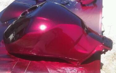
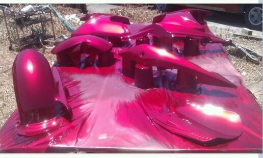
Ok the painter picked up the paint , its crystal red. What does everyone think?
nice color,mine looking at chrome or silver,i have friend who owns a paint shop,may have him do it or might do it my self,since i do a lot at work on some projects also i guess you are getting it air sprayed on in 12 hours about 10pm will be on the plane,good to come back home
I really like the Ironman paint scheme and that red is going to look wild on there !
Did you see the ARC reactor I'm working on fitting into the torso ? I'm not sure if I will do any gold accents. If I do I will use it sparingly.
I would really add some gold to it. From the waist up on some Ironman art, there isn't much gold . I saw the ARC reactor you got and it looks good and bright now . I can't wait to see yours complete. I saw you sold your spare Omnibot . I was watching the bidding on it JW
JW
Yea I still have the regular Omnibot which I may paint red as well , I already have a ezb on the way for it lol.
Ok I couldnt sleep tonight from kidney pain (i have a blocked kidney) and I was checking out the carry handles. I don't know if they are sturdy enough to handle the extra 15 pounds on a regular basis , so I filled the hollow cavities with fiberglass resin. Tommorow I will coat the handles in epoxy and fiberglass to thicken them slightly , also I will place a single layer of Matt on the backside of the handles where I filled the cavities tonight. I will post pics in the am. It's about time to mold in my iron man ARC reactor into the factory speaker location. I believe I will still put the speaker behind it though.
Awesome! Pics dude, pics.
@jstarne good to be back home to work on my robot projects,had a great time in china hopping to get my omnibot 2000 soon my first project since most of my parts are here is my roomba project ,then my brookstone rover hack since i think i have all parts for it now,many mant boxes of parts to unpack,my girlfriend did a good job holding them for me,so going out to a nice place to eat dinner with her
Ok I beefed up the handles , I will.sand these to get ready for paint. More.pics when I get the ARC reactor in.
have you check the instructables for ideas on the ARC design,many are on the site
@jstarne you making 2 different robots,one you hace a cd player and itx board ,OMNIBOT 2000 and another you have a ARC reator i guess where the missiles go in on the RAD
Ok I cut out a hole with a dremel carefully , I had to.cut.down this ARC reactor toy 1/4" on the edge so it would fit.
ok i see now,going to look great,looking at one day to make a iron man robot,but for now looking to first finish my irobot roomba project ,almost done and my rover project about 75% done a fter start on my omnibot 2000,kinda close to yours,not using a reactor or cd player,but does have alot more upgrades i have plan for as i wait for parts to come in one,i start on another,my irobot roomba will be about 4 feet tall
Ok here is my reactor lit up. The lines in the torso I will fill with epoxy and shave smooth tommorow with body filler. I recieved the four IR sensors and will drill out there holes and mounts tommorow. I picked up my.light sensors today and I already have the ir LEDs I'm using.for low light illumination because some areas of my house are dimly lit. Any ideas of a good placement of.motion detector /pyro electric sensor? rover 5 will be.here.monday and as I have illustrated I would like to convert my regular wheel drive to track drive.
in the front i front and sides,looking to use the big PIR'S ones kkeast is using or like the one on my ROVER robot design about 3/8 hole,they cost a little more ,but they have digital and analog output i like because of the tiny size,i like my sensors to almost be hidden
Josh that is looking SOOOO cool!
Thankyou Brett! I want to make sure this is one of a kind and looks good. If you have any suggestions let me know. Today I'm drilling mounts for the IR cliff sensors.
I'm wiring my drive section for B9. It is so nice to have some time to work on bots.
I know what you mean , I'm on LOA from work a few days trying to get this kidney problem diagnosed and treated and when I get bored I work on my bot
Ok before creating mounts for the IR sensors I needed to.clean.up the holes I originally drilled for cliff avoidance , I'm still undescided about also having a ultrasound sensor too in case there is too much bright light. I taped off the holes and filled with epoxy. They will be setup by the time I'm out of the shower.
I picked a creative place for the PIR sensor. The four buttons that were removed with the original LCD left empty holes. In a effort to use them I drilled out the holes and used standoffs epoxied in place for mounts.
The sensor is now part of the power management panel.
Ok this.is the.PIR .sensor.by.my.power monitor.display.
interesting texture to the paint . What did you use? JW
That looks sick Josh! I love the sensor placement.
that looks like a very good spot for it josh,good work,kinda hidden and blends in
Thanks guys. The texture is rustoleum black texture paint , always does a good job. Im out of it but.the sensor will get a light coat to match. I'm making mounts from several nuts and screws so this can be taken apart. The power management panel is so tight PCB boards overlap so I don't want to hot glue them in place. I am using one hole for a ambient light sensor too. I haven't mounted it yet but I believe I could just epoxy it in place. I also have two more challenging tasks for the torso. I have two circular WiFi antenna I can either surface mount or flush in, the light sensor , and I must have one or two intake fans to vent the torso while charging. Lastly I must put in a basic pc speaker 8 ohm 6 watts but I robbed the speaker location when I installed the ARC reactor.
Vent fan Two 2.5 in ring WiFi antenna Pc speaker Light sensor
Ps. I'm tempted to install "flashlights" that come on in low light, maybe one on each side if torso or base? Any ideas? I'll post pics of the things that must be installed. The reason I'm not installing WiFi antennas inside the base is my insulation has a layer of steel that most likely blocks signal.
@jstarne i picked up another omnibot type robot ,its a cross between omnibot 2000 and omnibot called HEAROID fairly cheap

looking to hack it soon one day,my robot room is like DJ room,so many many robots,looking to have much time and fun hacking themThat's a cool one robotmaker!
got it near $50 with shipping in good shape,shipping on omnibots are little high because of weight lucky where i got it from ,it ship from florida to hollywood ,fla or i would be paying about $65 going to call it BLUEE after my one of my favorate movie F/X2 ,where ROLLIE TYLER named a robot clown BLUEE,he had a telementry suit controlling ,i am working on a design
@jstarne looking for a good place to put the light sensor ,i see a tiny light or hole above the PIR sensor,good place to put a small LDR (light dependent resistor) very easy to make and use
That's a spot I'm.looking.at. I'm gonna pick up some.light sensors in.a.minute and try that.out
all you need is make a voltage divider ,or can make a simple comparator circuit to have a digital output and switch digita l output when light comes on,all is needed is a chip,few resistors and a trimpot chip is LM311 VERY COMMON COMPARATOR chip
Hi jstarne1
Regarding the flashlights you are thinking of installing. Have you checked if the camara you are using is infared sensitive . If so you could make a infared flashlight out of infared LEDs . and the little fellow could see in the dark.
Steve_c
some webcams have that built-in ,ones on ebay with IR leds and about $10 or less f
this one here was $10 from usa and now on sale for $5.29 with leds and 36mb camera,very good video when i tried it out
webcam with leds

Ok my second ezb was just received , I noticed Somthing different. There is no clear PVC or.heatshrink type cover over the Bluetooth module.Ok ARC reactor being molded in and lines filled as well. I forgot I'm out of sandpaper so I'm running to get s bite to eat and sandpaper. 60 grit , 120 grit , 320 grit , 400 grit and 600 grit. Switch paper one after another makes this process easier. No matter what I'm looking at a couple hours though.
i thought the EZB didnt have heatshrink tubing on it,since all 5 of mine didnt have it on sandpaper why not ue a sanding disc on dremel tool or small sander then use 400 or 600 wet,dry sandpaper from work they gave me a good size box with all types of sandpaper,and some plastic or metal work i use thier machine shop,until i get my lathe and milling machine
Josh,
That is coming along quite nicely....great work!
v/r
Kevin
Thanks KKeast , hopefully ill have this guy to a stage I can get paint done soon. Still have a few odds and ends to do. Tommorow the rover 5 comes and well double check how much trouble it would be to convert to treads. I know treads will cause my amp draw to be a tiny bit higher but I would also have great grip regardless of surface. On the agenda for tommorow-
make IR / white led illuminators
sand /shape torso
mount and mold WiFi antennas into sides of torso

As you can see they are circular , the center normally flips up and ring is the stand. I will look inside and see if the ring is antenna too , if so I imagine there is no harm in epoxy them to sides of the torso and mold the outside edges. I the antennas being part of the outside surface is the way to go. Any thoughts on this everybody?I must finish the blue dots for eyes. I must drill out a blue indicator light and put in a blue led. The current led is white inside it and shows up a blue green color I wasn't satisfied with.
-i must make a mount of some kind and joint with servos so the head can turn left ,right , up down. Anyone have a simple yet effective design? Help with this is appreciated , remember I have servos from the ezb kit...
-i must modify and mount the fan controller casing into the torso , then mold it in.. , it will be painted same color red.
Update , recieved rover 5 today , treads feel they are very good quality rubber with only a small amount of stretch. They are not stretchy as I thought. If I do my tread conversion I may need a idler /tensioner to be sure these stay on tightly. From looking they appear they will fit I only question how snug.
i got JSTARNE ominibot 2000 in today it looks good on outside,but arms need alot and lot of work,rusty springs and screws,but may not need them depends if servo's fit or homemade motor design i see on the hand grips is realkly messed up and one hand rubber grip is missing,anyone has the rubber grip pads for sale

Original plan for track drive , I fear it may not be as.tight as I want so I plan to install the wheels that come with the kit pressing agianst the belt to maintain tension.Basically I can use my dremel to carefully cut a knotch dead center of the wheels , its must be a couple mm wider than the teeth on the belt. Also I must cut out the dividers between each wheel so I can get the belt in and out. I don't believe it will need anymore modifications than that
i do some stuff like that at work in the lathe they have ,cant wait to get it,wont need my dremel tool to much about end of may looking to get it, its about $1000 total,but need to make a bench for it ,since very heavy item,have plenty of room in my shed my parents gave to me,20 ft by 60 ft long shed,took a special truck to move it,and my dad had it for awhile before he gave to me paid $12000 for it.metal outsid and wood inside
Geezer , I could live in.that .... And would too lol
funny part about it i did one day,but a very long time ago when i was young,my dad got mad at me and got kicked out of his house for a night,he did forgot there was beer in the small refrigerator,it was his wood work shop at that time
Ha ha ha , that's great. Here is a picture of my fridge....
Oh wait ! I got lost jstarne1 ! I thought this was your work space pic ! lol JK JW
JW
Lol ill post mine in a hour ...
mine is good bad soon,need to get one at home depo,rig part good freezer is bad but i do have a big large main freezer,i use to be a baker while back to bake alot and make ice cream and frozen yogurt alot,so i need a big deep freezer for my kitchen aid ice maker that attaches to my kitchen aid pro mixer,thats another big hobby of mine,getting pro kitchen equipment and bake alot hope to make a robot to help me in the kitchen,i have seen one college made one while back
Hey Josh - you could use a roller blade wheel as a tensioner. It has a nice bearing and rolls smooth. You could probably pick up a pair of roller blades really cheap at a yard sale or thrift store. They might take more punishment than those little tires that came with the kit.
Or even just go to a hobby shop and get some RC car wheel/tires - you know, the ones for the carpet RC racers. Those would be light and the dense foam tire would be easy to cut into for the track guide. Just a thought.
P.S. I will be posting a pic of my work area tonight. It started out as some space in the garage, then my wife gave me a corner of the bedroom, now I have it spilling out into the living room..haha.
Upgrade.update ok everyone knows even a video card you can.buy.used for 50 dollars is better than onboard graphics , so I set out to get a good.video card at low cost. At bestbuy I came accross this Nvidia GT 520 multi display card. It was about 120 but with a little negotiation best buy let me have it for about 94. Thanks bestbuy for you small but appreciated sponsorship....
Ok I fibbed lol there was a sale on this card when it came out in Feb , the sticker was on the shelf hidden under box , I took a pic and talked their.customer service into.helping a brother out I already know what your thinking "oh no there goes this bots battery life with a video card like that" well there are two possible solutions , first is I could have a admin login where.the PCI card is activated and a robot login where PCI is disabled / video card turned off. If I didn't want to go to that trouble it comes with software that's turns its gpu clock down or even off when no.monitors are detected like when the bot is autonomous....
This gives me productvity options of.multiple screens when working on my.projects
My.current power supply.is.rated at 160 watts , if I must upgrade I.will go to a 250 watt but I believe this will work fine given I'm using a mobile version 25 watt CPU..
Ok I started the track conversion , I removed my rubber tires very carefully so I could put it back on the rim so this modification is completely reversable.
I will need to cut a groove similar to this v groove in the rover 5 wheel , it must be consistant and dead center so the belt never touches the edge of the wheel.
I planned on using the wheels that come with EZb kit , they seem to be perfect size don't they?
i tore down the omnibot i got from you JOSH ,what is the white foam under the speaker,looks kinda like soap,and its in a few other places too
It's probably residue from where it was whitened.
no dont need any speaker my friend,just wondering,might reclean it again ,just took it apart to see what to order for it and my plans do you have any rubber grips for the hands ,one is missing or any ideas to make one i also may make new hands if i cant find stuff to fix it also on base did you measure the torque of the motors with weight
Ok taking a small break from these treads that are stressing me out , I need to do cutting so I'm marking everything on.the torso and wheels where I need to cut the V groove and I need to knotch out the torso as well so there is room for the Dvd / blueray drive below the power management panel.
I believe I will also mold in the bezel for the fan / temp controller , this will cover up some labeling but it will also make it look cleaner.
@robotmaker , no I don't have a way to measure torque but I did test voltages between 6v to 12v the sweet spot felt like 9 volts.
way to measure payload handling (torque) is after you finish the tracks or if you did it before, is run the motors and bottom chassis only and add weights till is comes close to stop
Ok I took apart the fan controller , and flushed it into the torso cutting knotches , I with glue all the way around with epoxy and fill with body filler.
None of the mounting.points or button are obstructed from what I see here in the test fit.
Ok I cut the torso to accomidate the Dvd drive , I attached a ledge where the Dvd drive will be held with double sided tape. I will cut a piece of wood to affix on top of the drive to give me additional mounting space for electronics.
It's black so it doesnt show well however the dvd/blueray drive is in place above the fan controller . This couldn't be fitting together any better
on my omnibot 2000 i finally tore it down and removed all screws,metals,electronics ,gears and motors out of all the plastic parts ,next is to wash it,bag it and box it for latter also researching motors,servo's and other parts needed and then order them,so when i finish my other 2 builds it should have the parts in by then i did have plans to work on RAD 2.0 but the little guy will have to wait its turn OMNIBOT 2000 want more
Hopefully you won't show me up and outdo my.omnibot 2000 lol
it may,using TPA81 SENSOR
Paint is coming soon
Ok I ordered from solarbotics a pan and tilt kit. Here's the pictures.

This is for the robots neck , head tilt and left right.motions. I will use standard futuba servos that came with my ezbhow much was it,one i like is lynxmotion pan and tilt ,got it fast
lynxmotion pan and tilt $9.95
Ok u need a place to mount 4 dvi plugs , so I'm putting in one larger fan and cutting out spots for the 4 dvi. Any suggestions appreciated.
Current exhuast I must.cut
This is a drawing of.what I'm.going.to do...
i see alot of changes ,getting better
jstarne1;
I bout that pan and tilt kit from Spark-fun for a "Neck" as well, but caution: it is NOT that strong, I almost snapped one of the pieces just handling it too hard:(
plastics dont hold up,i bought one for a sensor awhile back and it broke,thats why i only metal pan and tilts ,like lynxmotion ,also if you buy the parts separate you save money C- bracket and servo bracket,but $10 is pretty cheap for one,only add the servo you need solarbotics you need to buy the servo's to go with it
good news about solarbotics is about the same price and metal ,but need to wait a long time and shipping high,canada
Oh bad news bear , ok.my roomate was repeating steps to make a home made smoke bomb and it unexpectedly blew up. Spewed molten material and burned through the counter. Here's pic of the kitchen after things were under control. I have not been home yet to see this I'm still at work.

He told me the plastics melted on the front edge and left some burn marks. It may be salvagable.On a side note I picked up two antecedent 80mm fans from best buy with speed control option to hook to my fan controller.... One fan will intake the other exhuast.
dam sorry to hear the JOSH looks kinda bad hope soon it can be repaired
That sucks ! When is your roommates funeral? JW . I guess you can look at the good that it wasn't painted yet . That's a real bummer though
Hopefully I can sand it and fill with body , if not I must get another torso and redo everything.
if not wacked out of shape,filler should be able to fix hope your roomate pays for everything,it wil teach the person a good lesson you really did a great job on it i had some like that happen to me my my wife that did it and was very mad and made her pay for it,also she my ex-wife,not because of that,i do see her sometimes she comes over for my birthday and christmas and other days
@josh - Duuuuude....
I know right lol , its probably not too bad , I will press forward and either repair this or use my spare torso and mount the second ARC toy I have in it and pic up where I.left off with the torso , it only.put be behind 2 -3 nights work , as long as its less than that to repair it I will otherwise I gotta cannibalize the regular Omnibot I have for.his chest.lol
does anyone know what type of plastic is the omnibot shell is made of ,like pvc polycabonate or acrylic (pexiglass) need to oder some plastic sheets
It's ABS plastic , that's why it turns color over time.
i was thinking it might be that,they only have it in beige or black,so i guess beige then paint it white or match the bezel thats black,might need to repaint both bezel and the black ABS the same black color,bought a few cans of special plastic paint in white for another robot design,so will need to get a can of black plastic paint
Ok the torso is garbage now , so.roomie is.buying another Omnibot ...
Lucky I.found another bot for.about 100
Ok I recieved my 6 amp continous , 8 amp max , adjustable step down converters. They were 15 dollars each...
Having 6 amp overhead I could use for drive motors or all the high torque servos.
Those seem like a deal at that price ! JW
JW
Yea , if it wasn't for the internet.... Lol
same one i saw,and saved it in my lists mine was $12 free shipping dc-dc 8 amp free shipping
Even a better deal !
also got rad 4.0 and look great to hack for EZB
I saw those and wasn't sure how well it would walk? They look great though !
easy to add servo's to it,and has motors with wheels on bottom of feet going to add servo,s in legs ,arms and head,motors in bottom of feet should be ok
Ouch josh, that's rough.
Ok. Due to.video card issues , I took my video card back to best.buy.and.moved up to nvidia GTX550TI 1gb DDR5 PCI graphics card, spent a little.extra , agian take in mind this will be deactivated whenever my bot is running around because I'm sure it draws as much or more juice than.my.CPU lol. It supports two monitors , dvi, VGA , hdmi and tv out so I'm covered on all accounts. I will.usually use hdmi...
http://www.bestbuy.com/site/NVIDIA+-+GeForce+GTX+550+Ti+1GB+GDDR5+PCI+Express+2.0+Graphics+Card/2375089.p?id=1218323853938&skuId=2375089&st=nvidia%20video%20cardnvidia&cp=1&lp=3
josh
i was looking to get a video card for my robot computer and found out i needed 250 watt power supply,it was little like that one,and didnt get it because there is no 12 volt dc-dc converter to handle it so before you put out money for that board i would check what power supply is needed and see if your dc-dc converter with handle it,second you will most likely need a much bigger battery to handle the load of it
wow found out the power supply needed System Requirements Minimum of a 400 Watt power supply
here is the link to it
psu recommended
PSU recommendations are very generic , at max draw this card is 138 watts but that's overclocking , toms hardware rated it at 116 with stock settings. I ofcourse will Disable!! This card when the bot is on battery , it will be a power saving profile in Windows. But when I'm gaming I would like to turn it on. You are very right I will need a 250gig watt power supply , I'm looking at a M4-atx 250 watt continous , 300 watt max PSU
http://www.ebay.com/itm/M4-ATX-250W-6V-30V-Wide-Input-Intelligent-DC-DC-Power-Board-/310394249495?pt=PCA_UPS&hash=item4844f06117
Taking in mind my.motherboard only draws about 35 watts and this card 138 watts , think this will do the job ? ?
then add hard drive,and cd rom ,anything hook up to usb problem you will see is 35 watts is normal power no running programs running programs takes up much more,then video alot more ,thats why they have it at 400 watts when then meen 400 watts its total power of cpu and running programs, hard drive cd rom even if you use usb still draws some power, think at using that power supply you will 10 amps battery for may be 3 hours run time ,i have a 120 watts and found out total draw was 8 amps at 4 hours with any video video uses the most power of the power supply and cpu,for that board you will need a very fast computer since its mostly a gamming video card just some ideas to help you out,i would first try it with a ac power supply first and see if it works most cheap old computers use a 250 watts
good idea ask a tech support guy at best buy ,see what it says wow that board looks like it draws near 25 amps SINCE THERE IS A FUSE AT 25 AMPS it mostly about right for almost 10 watts power you have about 1 amp draw i think is .85 amps per 10 watts if i remember right
here is another idea to help my good friend out,use a 12 volt ac power supply with a relay switch,and use the wall socket when using the video card and dont use any video when running the robot,the card shold have idle current
@Josh,
I thought your MOBO had onboard video (VGA out)..that would be better than adding a card that is going to suck your power down, especially any of the NVIDA cards.....
Sorry to hear about your bot too, glad to hear you got another one lined up.
Another thing to consider with your video...why go with a fancy PCI video card if you are running a small composite video screen... (unless you got something different from the monitor you posted a while back). You will also need VGA/DVI to composite video conversion which will suck down more power as well.
v/r
Kevin
@kkeast thats what i try to tell him that ,trying to save him money and trouble i think he said wants as his main computer to hook up to a flat screen or better monitor only idea that would work is use a relay to switch power from 12 volts to 120 ac volts and not run the video card when using it as a robot
@kevin , the video card power will be disabled when robot is on battery , he is also my pc so when I'm gaming I want to enable the graphics card. Otherwise yes I have onboard video.
some bad news JSTARNE i check the specs on the dc-dc converter you are buying it wont work like you think it will,it 8 volts more on input to get 12 volts out,glad i didnt buy it so for 12 volts out you need 20 volts or more in,check the info on it,it will say that i am looking at making a circuit for dc-dc converter to handle up to 10 amps with 6 -30 in and 3 to 30 volts out ,its called a dc-dc boost converter
@robot maker , the.heavy.duty voltage converters need a 4 volt higher input than output. I purchased them for the.purposes of lowering the 12+ volt system down to 6 volts to power all the high torque servos , which there will be at least 4 , plus I wanted to reduce voltage to drive.motors to 7 or 8 volts so I don't burn them out. Ez b.will get reduced.voltage to 6v as well.
Industry Grade DC 8-40V To DC 12V 10A Step-up&down Converter
Ok I already know I must upgrade power supply , and I was trying to figure out battery management switch from ac to battery. I have descided to go buy a small APC battery backup and.use its brain , it charges batteries when on ac and seemlesly switches to battery when I unplug ac , it also monitors battery and will shutdown before battery is over discharged. This feels like a much simpler setup.
@JSTARNE i designed a few of them ,not a hard design ,switch circuit took a little extra time,plus any current output adjustable,voltage adjustable and cell count adjustable mostly yu are looking at is a simple battery charger that charges the battery ,then shuts of the power when battery fully charged,what bad about that does add some weight to already other weight
idea i have is to use a connector for charging the battery from a seperate battery charger and use low voltage contact plates that robot bumps in to like the neato does or run over a contact plate this way you only need a 12 volt input and not a very big battery and use EZB TO CONTROL THE SWITCHING,solves many problems and have a auto hombase charging design
thinking soon your robot will weight over 100 lbs with all the add-ons maybe more

Alright , I gutted this APC 390 watt unit. It took a standard 12v battery so its a perfect match for my 12v existing batteries . This consist of a 8 inch long charger/ controller.board. a transformer and a relay. This should easily fit inside my base. I identified.that I only need three wires to power my PSU on.the computer. The yellow , blue and green. Yellow hot , blue nuetral , green ground. I also picked up a thermaltake 450 watt switching power supply. This sock came with a data interface to change profiles as soon the power changes to battery. This triggers the deactivation on the nvidia graphics card to greatly reduce current draw.Here is my power supply I picked up today , thermaltake a good brand though not my favorite , 430 watt power supply but I'm sure I won't use but 200 - 250 watts even under gaming conditions so this is this is plenty.

I needed Somthing with higher capacity than my current 160 watt.@jstarne1,
So long as your not a hardcore gamer I run 1000W on my quad core with nvidia cards in SLI.....I would blow that thing up if i tried it.
Just be careful....! Good Luck!
v/r
Kevin
Lol , I'm sure this cards plenty , I will mostly play , Diablo , starcraft 3 , hack and slash games ect
YES that psu will handle the load on the gutting battery charge are you add that inside your robot
i am getting super computer its a gamming computer,but only using it as a video server and for programming,have 3 main computers in my computer and each room including the kitchen i have one looking for one of the best gamming computer check this one $400 with is cheap
asus super computer
and yes KKEAST using WINDOWS 7 32 BIT with ICORE7 EXTREME
@Robotmaker,
Nice Board...but Dude, why would you NOT run Win 7 64 on that thing!
You are getting robbed by not running it as a 64 bit machine. Plus if you are running 4 gb or more of RAM you are wasting resources... as I am sure you know 32 bit OS can only address 4gb of RAM total...so if you have a 1GB vid card in that....Windows is only using 3gb.
I could imagine that thing with 3 cards in SLI.....problem is finding a game that could leverage the power!
v/r
Kevin
IT HAS 24 GIG of memory,i have a very good IT TECH into high end gamiing that has this one and told me about it and he uses 32 bit windows 7 he use 23 video card i think he has 800 watt power supply yes i know very ewell about windows using only 3 gig of memory ,thats why using 24 gig of memory,i have a ICORE 3 WITH 16 GIG ,AND NEED A ANOTHER SUPER FAST COMPUTER
@robotmaker,
Sorry to tell you that 20GIGs of that is just sitting there on your box......not being used. Go to Control Panel, System & Security, System. Probably says your system is using 3.6gb or something but wont read any higher until you go to a 64 bit system.......its a logical limitation of a 32 bit OS.
Be careful with an IT tech that is telling you that....this is pretty basic IT stuff....
Windows Release Memmory Limits
i dont why i said running it at 32 bits,i meen 64 bits i made a mistake,my ICORE 3 RUNS AT 64 BIT WINDOWS 7 ITS ONE OF THE MAIN REASON TO USE WINDOWS 7 because it uses 64 BITS for higher memory,didnt proof read my posts before i post them sometimes
Anyone have a win 7 key and.maybe a copy of it?
wont do any good without the cd
That's what I meant by a copy of it , or a copy on a usb.thumb drive
no what i meed you need the windows 7 cd to go with the key, the key matches the cd
Ok update , I started cutting the track groove in the center of a wheel , first one was difficult but I bet.I can.do the other three faster. First I had to make a template so that when I mark each wheel.they are the same. Then cut dead center all.the way around. Lastly I must bevel.the edge with my dremel them hit it with sandpaper to get any buggers off.
It seems to turn smooth but I want to make the other three a little tighter to reduce and play.
I see your room mate cleaned the robot destroying debris off the stove! To bad you dont live closer , you could come over and whip those wheels out on something I have here. I still feel really bad about the robot body and all the work you had put into it. JW
Yea I didn't have the heart to work on it all weekend , I do have a replacement body already but when you work for a couple days to get it all just right. I picked up a sock backup and robbed the brain over the weekend.
what you need is a milling machine,if you have a xy table and a drill press you can make like a milling machine easy,it would make very even grooves,othr way is easy is to have the wheel mounted to a drill and have the dremel stationary and have the height adjustable,they do have a drill press for dremel tool,i use mine alot,most bought every attachment i can get for my dremel tool ,xpr4000 model lastest one but still you are getting there,good to see you have close to finish
my roomba project has just a few more days and it will bbe done,almost 4 feet tall with many sensor added
i see you like using the blue painters tape too
Man Josh, that looks like a lot of work. Too bad you don't have a drill press (bench top models are pretty cheap). You could chuck up the wheels for rotation and use any number of tools (triangular file maybe) to make those grooves. Just a thought.
@brett. It only took 20 min to finish that wheel , I would be done.before I got.back from harbor frieght tools with a new press lol. Oh I didn't know till I recieved my solarbotics pan/tilt kit but I need a micro servo , my standard are way too big.
I'm determined to have a video card in this machine. I must raise the motherboard mounting position 1/2" vertically , after a few measurements I found I have wiggle room..
I do have about 1/4 in wiggle on remounting the axles lower as a last resort as well. I want to.avoid it but I will cut.the nvidia fan shroud as a last resort as well.
Dude, I'll send you a micro servo. Just email me your address again. Need anything else? Sonar sensor?
dude looks like your omnibot when done will weight a ton dont need a mill machine for harbor freight, just a dremel drill base and a second drill to turn the wheel super simple and easy to use and make and can make a pro cut in seconds
This may help with your video card location: PCI-E Express 16 x Riser Cable with Latch
i see many others on ebay for under $4 but without latch
Do you still need a windows 7 disk (64 bit) If so drop me an email with your address. Algeraist@AOL.com
I live in Australia so it may take a while to get to you.
Ok jstarne1! I think you win for the longest thread on the forum! LOL!

Ok phase 2 planning , a second smaller , simple robot will vacuum kitchen and living room..@ww321 lol I promise I didn't plan it that way , but I wanted my build to be educational and informative , lots of "how toos" and illustrations , and before after pictures are priceless in value to someone who is learning or.trying to.repeat any aspect of my project.
Here is a Isometric sketch I.did.on my.last break.at work.... Forgive its simple look lol , also a topview of possible sensor.locations.
A side note I descided for airflow reasons I perferate 4 spots on the omni 2000 base , two areas for intake , two exhuast as I believe one 80mm fan will realistically not be enough...
what did you do about the cliff detection ,did you use my idea on using IR SENSOR instead of SONAR
I don't have either.mounted at.the moment , I've had really mixed thoughts , dj thought a sonic sensor would be great so honestly I'm a bit confused , I bought 4 sharp ir sensors to use instead but I have not mounted them. For anyone interested I.have a roll of rubber sound deadening mat and fans to cool ezb and motor controllers I'm.hooking my friends up with.
if you read the specs on sonars it wont work well on material like carpets,cloth,sofa's,foam
also look at NEATO XV11 VACUUM robot they use IR and does the ROOMBA on the bottom for edge detection
another sensor i have since you are making a vacuum robot is a dirt sensor,do you need it
Josh, I absolutely love the omnivacubot design! He looks soooo cool! I actually have a roomba board if you want it. I know that DJ has controls for the roomba, maybe you could combine the two to control your vacubot? I may even have a few of the sensors off the roomba, I'll check and see. If you want it you got it. Just let me know your shipping address.
bret i not sure it will work,because DJ hasent add on the roomba to read the sensors,only control the the roomba,but it might be able to use it to control the motors
JOSH here is more info on using sonars facing carpet The front-facing sonar sensor detects obstacles straight ahead. Since sonar sensors tend to have a wider beam and range than infrared sensors, it makes a good general purpose obstacle detector. However, there is one "gotcha" about sonar sensors that had me puzzled for days before I figured it out. If you mount such a sensor too close to the ground, it will detect small irregularities in the floor surface that you wouldn't consider obstacles. For example, my dining room carpet is barely an inch above the tile kitchen floor. Nonetheless, if the front facing sonar sensor is mounted less than about 4" off the floor, its beam bounces back off this rise and the poor robot can't get out of the kitchen. IR sensors can be mounted much closer to the floor without suffering from the same problem.
look on the internet there is more info on sonars not able to detect anything cloth,sofa's,carpet,foam the sound absorbs and blocks it,same with speakers using foam or acoustic material
Power diagram for vacuum bot ...
another wiring change
Actually this is for the smaller vacuum bot , not.the omnibot 2000 , I really should name these guys...
oh.i see the head of it now,one with the dome top ,omnibot
i have 2 of them at home,also hope you are adding fuses to it
I need a dome , do you have a good one?
no sorry ,mine is scratch alot,need to rework it,bought a special scratch removal kit and special sandpaper to see if i can remove the scratches,other one restoring it there is a place that has domes for sale to fit it perfect $40,same size only the lip needs a little work
Josh,
Two questions probably simple answers :-
Why the dc - dc converter can't the EZ-B run on 12volts ? For the Cam why don't you run the power from the EZ-B ?
I think I know the answers to these questions but I'm still learning so thought I'd ask.
Regards
algeraist you need 7.5 volts any higher the regulator gets very hot,you should be able to run it from EZB only noise might be a problem,i takes very little current to drive it
dc-dc converters are very good to get rid of noise,but low drop out regulators are better,but need a filter,i design dc-dc converters at work
aslo whats bad about its very important you watch the discharge level of the battery you are using ,if you go too low ow of voltage using a dc-dc converter,when you try to charge it ,it will go bad so very important to have a voltage monitor ,witch is mostlt a zener diode,and a voltage devider hook up to analog port,or a simple voltage comparator to digital port can buy them but will cost you 3 to 4 times mores ,parts are under $2
@robotmaker. , yes I fuse between , battery , power supply , before ezb ect , but I didn't draw them in.
No you can't run the cam from ezb digital out , you either must use a switching transister or Somthing to drop the voltage from your battery , connecting this cam to a digital port will smoke it. It draws between 200 ma to 500ma depending on charge level of the battery. See camera mod to bypass battery so this current draw is consistent and low as possible.
no not from digital output,from 5 volt output at the regulator ezb uses 5 volt low dropout regulator,and hight current i think its 5 or 7 amps i see other have the address up ,so can put mine up too i am in hallandale beach,fla ,also my email s roboticsdesigner@yahoo.com my main email jamericanfreddy@yahoo.com my girlfriend help make that name part jamaica part america part freddy my name,she a very pretty jamaican lady,been to jamaica 52 times so far
Linky to the solar charger/PSU unit pls?
Wow! this robot is definately taken on a life of its own! Congrats! Will you be using a pan/tilt joint within his shoulders? That would be a neat look!
@glick click , ugh everytime I hear a good idea my wallet gets a little lighter. (jk thanks . I'm gonna measure when I get out of bed but that does sound like a good idea and could give the arms greater range of motion. I just recieved my pan tilt bracket for the neck.
@ndavid yea I recommend a solar charger because I could go from charging to running without interuption. It basically makes your bot have its own UPS backup. This is a 10th amp model good for most bots , but they come in 15a , 20a and higher... http://www.ebay.com/itm/150771239291?ssPageName=STRK:MEWNX:IT&_trksid=p3984.m1497.l2649
I have two choices , either use a solar PSU or a ups backup brain and a regular PSU... I'm not afraid to go back and change Somthing that doesn't work efficiently but the key here is that it works . Hope everyone has a good morning , I'm going back to bed its a little early for me to be up.
josh i see you are using a transistor and a relay for driving your vacuum,not a great idea ,much power lost,should use a mosfet,and will save you money too,mosfets can be driven from digital output using a 260 ohm resistor,mosfets are very common for this and h-bridges,and dc-dc convertersplus alot smaller in size
Can you please draw a diagram of how I would use a midget like that?
same as using a transistor ,only using a mosfet but will need a transistor to drive it i found a circuit on the internet close to it, use only Q1 and Q3 the mosfet ,plus R1 and R3 MOSFET CIRCUIT IT IS A H-BRIDGE circuit ,but you only using one mosfet mosfet part #IRF3205 IT IS RATED AT 110amps but anyone close to it will work without a heatsink needed D2 is not needed because this mosfet has one for protection
Oh yeah O forgot to tell you another idea.
Think 'pico projector'!
thats what i am using pico projector on mine,to watch movies on the wall
How many lumens is the least to think of using?
Ok here are some pics of little brother Omnibot and the donor shark vx63 vac. The original gearbox and wheels are perfect but I'm kicking around the idea of using this 4wd tracked rover 5 which would offer significantly more power and more traction to man handle the vacuum motorized power head. Any suggestions? Should I keep the original drive systems? Take a look...
I plan on having one 12v 8.5 ah yusa battery that should allow this guy to vacuum for 2 hours.
@glickclic 20 lumens for brightness,shows a very good video at 6 feet away i am looking at better ones ,prices will be high as you go up in lumens output plus adding a design i made to match the brightness level of the room
@JSTARNES thats not much amps only 4 amps per hour are you using a computer board on wheels i would add a strong motor for more load torque everytime i design a robot i weight everything going to put inside and any extra changes on outside,plus the weight of the robot with the parts needed then i take the chassis by its self and put the total weight of everything using like cans or something heavy and run using a power supply with amp meter inline with power supply and see if it stalls first and see how current to draws and then add weight little at a time to see when it stall ,and measure the curr e nt fast or use a peak holding meter,this tells me 3 things,how much current it needed,sta ll current for h-bridge and stall shutdown circuit and how much extra load can add to it
stall shutdown is very important,because you dont want your motors to go bad incase of a rock or something in its way and switch off the motor
all this will save you much time headaches and extra money spent
@robotmaker no I.believe I will only have ezb.in.the vacuum bot and control it from.my computer or tablet. Wieghing.the parts it looks like it will only weight about 12 pounds extra mostly due to the large battery.
that including omnibot and vacuum cleaner,i know motors for vacuum takes alot of power ,like in NEATO XV-11 and ROOMBA robot vacuum cleaner and its very small about 12 lbs not including a very large 12 volt battery like your use
also motors on neato xv11 and roomba are very good for robots ,high torque can handle over 35 lbs and bigger then one in omnibot,but will fit,wass checking the specs on that motor used in omnibot not such great torque,it will come close to handle just your omnibot maybe,when companies design robots the motors they use just barly handle the toy and just a little more ,only one good reason to save money
another idea just in case it doest last for hours is to make a low cost rechargable 7.2 volt battery pack at 3 amps for sensors and EZB and may be motors check my post on building low cost battery pack
Update on incoming parts , I bought a l298 motor controller , 4 of them from ebay but one has a broken peice , a little push button , I have no idea if this makes my controller useless , because I don't know what the little button does.... Any help here?

There's a little white button at the bottom on right , what is it?It appears to connect or disconnect the onboard 5v regulator. Which is unnecessary with the EZ-B providing said 5v.
check my reply on using that board ,it tells how to hook it up and EZB file example to use it since you and others wanted to know how to hook it up
on the switch i just tie the connects togetherm,its not really needed even if the switch is good ,just incase when using the board the switch doesnt pop up from vibration
Tiny update , my vision of the omnitrackvac. Lol
Cool!
Yes Brett , I could definitely use that sonar sensor and micro servo. I'll email my address.
good deal, I'll send them to you as soon as I get it.
I tested the Omnibot drive section , it was able to lug around 40 pounds at a rate of around a foot a second I guess , I made a video , I will also check it on carpet as well but I don't think it will be an issue at all.
YouTube video... https://www.youtube.com/watch?v=QNT2SqCGiNo&feature=youtube_gdata_player
Is that with the stock motors and gearboxes? That is really impressive.
Yea no mods at all its completely stock not even gear lube lol.
i see you tried my idea thats great ,i would measure the current too,carpet will always take more current on mine i adding much higher torque,to carry beer's and alot more,looking at adding 12 volt 20 amp battery or more for a very long run time,got mostof my parts in
 and this week willl have my ROOMBA PROJECT done,with photos and code
 then start on my OMNIBOT DESIGN
Tested rover 5 with 40 pounds , moves just as well as the Omnibot but the chassis flexed some under the weight. Otherwise it was peppy.
Tested rover 5 with 40 pounds , moves just as well as the Omnibot but the chassis flexed some under the weight. Otherwise it was peppy.
Ok here is the inside of.the donor vacuum.
There is not much to this vacuum unit at all! It should be fairly easy to fabricate it into the back of omnibot...
yep only a vacuum motor and casing,cam almost make one using a motor and a tube
@Josh,
Watching you work close here! Great job. I am looking around and seeing that I may the parts to build one simular....Love your design so far!
v/r
Kevin
Ok I tested track system on carpet , after doing one 360 degree turn with weights the rubber treads derailed. Power/torque appeared not to be the issue. It appears for carpet use tracks are not not not the way to go , I'm reverting back to normal Omnibot treads . Failed tests do not mean we are set back , they are but the stones paved in the road to success. - J starnes
The beginning of this project I had the goal of a omnibot vacuuming and cleaning my house. So I began cutting down the shark vacuum (which are top performance to dollar ratio by the way!).
i have all tiles on my floors,so when i get a chance,looking in to a design to clean and wash mine i know my girlfriend will love that
I'm obviously not there just yet but I'm thinking of that too , having a sqweegy of some kind behind the brush and maybe a liquid sprayer or steam sprayer as well. Most likely I would use the shark cordless steamer for that as well lol. Unless anyone has any better idea
@ kkeast. Thankyou for watching and your support , the greatest form of flattery is imitation , so I'm definitely good with you utilizing design ideas
Since I'm not using the Dagu rover 5 robot chassis (i have two) after these test I have two up for grabs , I will stick them on eBay if noone says they want one. I would sell them for 30 each , unmodified like New in the original box.
i am going to use the swiffer design,since i have extra one and looks very easy to attached swiffer doesnt take much current also
Are the Rover 5 tracks one piece? Or are there links like a roller chain?
@Josh,
I will take one if you don't mind!
email me if that is cool: kevink.34@gmail.com
thanks!
v/r
Kevin
N David , they are one piece and.they stretch.like they are made of latex.
I took a night off for the sake of planning , I want to filter the exhaust of the vacuum , maybe.route it inside the torso and have a vent that releases the filtered air? Hmm , if this works well I may get another vacuum and do a similar mod to the big omnibot 2000 as well . I may post better details based on.measurements and Photoshoped pics to see what it looks like.
Much needed venting modifications , How to !
Most robots need venting to maintain proper temperature. Fact is the hotter electronics get the more watts they draw and in some cases can overheat. For the.longevity of your equipment you should plan to add proper venting. Venting can be done neatly and in such a way you blend them into your project, this is the standard size most the electronics industry uses.
Step one! Find a power supply or case that has the standard honeycomb pattern vents. Also pick out a drill bit that will slide through the hole but its super important there is zero play.
Second step - use vents modestly , they only.need to be slightly larger than the fan that will be drawing air through. , find a good place for your fan on the inside of the case.
Third- like up your honeycomb template over where you want your vent , be sure to count the rows left to right and vertically so you won't have any stray holes accidentally drilled. sing masking tape works well I'd you need to make more than one vent.
Fourth step- carefully line up.the holes to be horizontal against any edges on your robots body. Hot glue it in place with several large gobs. Don't worry these pop right off si smooth plastic. Drill your rows of holes and make your desired pattern.
Extra step! For those who want max airflow , on the inside of the case you are venting you can UAW a unibit or counter sink bit to make a cone shape on the vent on the inside , this decreases resistance and is proven in increase airflow by 15 percent (that's a lot guys) so you get the most out of your tiny fans...

OMy biggest challenge is making the left and right side appear to perfectly match , fortunatly this pattern provides a optical illusion , as long as there are the same amount of rows horizontally and vertically your eyes don't pick out that they really are not the same and maybe not.perfectly aligned the same.... This turned out really well I think .
.
Ok here's the final product of the rear vents , I was really sweating this and gritting my teeth hoping I would make a dumb mistake as this would be visible.lol . I will do a couple on the sides as well as I need a 4 reasonable sized intake vents. What do you guys think?
venting mostly depends on how much heat there is,if using a ITX board you need some venting,some motors might need venting and regulators what i do since i have equipment is to measure and monitor the temperature of inside of the robot design and add as needed on motors its very good idea to add a temperature cutoff circuit to it,fairly easy to do with simple diode as a temperature device and comparator circuit,motors over heat,sometimes of beening on to long,or stall conditions
JOSH it looks good,i use them also as templates
This looks really good Josh! And good tip as well!
Thanks Brett! I imagine you could do this in a couple places on your base to ensure really good airflow for that new monster motor controller! I bet that rad base can get up to 5am draw per motor on carpet turns. Anyways I found this to be a clean way to make them. Have you bought the 10a controller like I have yet?
Yup, waiting on it to arrive. Can't wait.
one mine using a 30 amp controller ,using a stronger motor to carry items,it handle easy 70 lbs ,plus will have a feedback called magnetic quadrature encoder design i made,how far it goes in feet and how fast and forward and reverse
the robot in my AVATAR uses optical quadrature encoder,plus a few other designs i made,but in the small robots kinda hard to use a optical disc
magnetic encoder is a hall effect sensor plus a magnetic disc for quadrature encoder you use 2 of encoders at 90 deg to each other,can use one,but with 2 you get foward and reverse counts
JOSH is your vacuum you are using have a 12 volt motor,took 2 vacuums apart and they using 120 volt ac motor,i guess not all vacuum cleaners are a like since i have many many parts from the NEATO XV-11 robotic vacuum cleaner ,might look at using it,plus so many of the IROBOT ROOMBA vacuum cleaners over 25 of them is another idea too
another idea i have for my friend JOSH i have many dirt detectors can give it to you free,analog output,they use them on the bottom of the roomba brush for detecting DIRT
@robotmaker yes its a 12v motor in the.cordless vacuum , I picked cordless because they give a mix of real suction power with real spinning dirt brush that has several times more power than a roomba. I don't know exact current draw but the 1.8 ah battery that.it comes with runs it for 20 to 30 minutes , it has a low battery cutoff circuit so once the battery cannot maintain full speed on the motor any longer it trips a tiny relay to turn off the vacuum. This is a feature.of shark vacuums I found useful for robot applications that prevents over depletion of battery @robotmaker. Dude I would love to have some free sensors and stuff ! Dirt sensors are a great idea!
Update on incoming items : I have 4 mg645 servos and lynxmotion pan brackets I'm using for omni 20p0 shoulders.

Two of these on.the way...thats the lynxmotion pan and tilt i posted awhile back ,much much stronger the pololu pan and tilt mg645 servos are great,i am double the power o5 the mg645 servo for my arms roomba's are very weak,but the NEATO XV11 is about 3 times or more suction then roomba or shark just like the motors are more then double the torque
on battery protection super simple to make a low battery detect using analog input first circuit draws extra current,plus no a great to switch power off with a relay,thats old school design mosfets are the way always to go
i saw a shark vacuum cleaner at target for $85 ,does have a fair enough vacuum,not great small problem with using the NEATO VERY powerfull vacuum cleaner ,you do need to make a canister for the dirt
on the sensors let me double check them for wiring hook up first,since no specs on roomba or neato stuff
@robotmakerI tested the vacuum under regular use and it did really well , the shark I mean. hats your email again/
that model vacuum cleaner over $100 unless get lucky at a yard sale or thrift store.and it will be very hard to tell if has a AC MOTOR or DC MOTOR,i took 2 apart and found out both had AC MOTOR,all type of cordless has them but very high cost or not much suction whats "hats you email again/" meen
since i got another omnibot my 3 one,looking to use the swiffer ,since all my floors are tiles,had carpets before and found them ,first hard to clean even with the best vacuum cleaner,i had DYSON till sold it ,the best ever on the market and well worth $300 paid at that time for it,tiles cant trap in dirt like carpets can,then i have throw rugs as needed in my place,easy to clean and wash
I said what's your email , the vx800 I have sells on eBay for just 40 dollars , I used it a couple months before I cut it up. It worked well enough I had no reason to use my regular vacuum , but half my house is tile or hardwood anyways.
I can't wait to see how well those shoulders work! I've got an omni on the way and will follow your progress and best tips.
ebay does not have any right now,not even new or parts stress new is $129 on amazon
email is jamericanfreddy@yahoo.com one i did bnoticed about putting a vacuum cleaner on a robot,it wont get under tables or couchesn like very low height NEATO XV11 does,can do any area but i buy mostly for the LIDAR lasers to sell for robots,one of the best navigation sensors you can get,most over $1000,neato LIDAR near the same accuracy i sell it with a special cpu tracking usb board and python code that was made for it
http://www.ebay.com/itm/Guro-Pro-Operating-Shark-Cordless-StickVac-REFURB-Fl-/190671680453?pt=LH_DefaultDomain_0&hash=item2c64eaf3c5
I see a few of them...
$i see that for about $70 with shipping and another $70 free shipping and one for $119 on that model still very high
you said your tracks not good on carpet,they should work perfect on carpet if motors have the right torque (very important) and tracks have good grooves in it,for gripping power i made a ROVER bot with tank treads and they go over sand ,rocks ,carpet and logs thats main reason they use them on tanks
Venting the back of the torso , most holes came out perfect only in two spots the holes were too close together because of the angle I held the drill through the template. So I may fill just those two with Bondi gold and redrill so its perfect before paint. These two vents are tall enough to mount 4 fans , I'm thinking of continue the holes down another 4 or 5 rows which should be plenty of room for two more micro sized fans.
it looks good and getting there
TINY update - parts are in.the mail. Shoulder servos and pan brackets , a 250watt mk4 dc pc power supply , a 45amp charger /power supply 12v to keep at my desk. I ordered the new PSU because.it would save me 5-7 pounds on total weight.
@robotmaker read that post again , yes I love tracks but the ones I bought for the project were too stretchy and once I added 20 pounds of weight the tracks would derail off the drums , I'm not abandoning the idea just going to work that into the project later when I get segmented tracks that will not stretch and derail off the drums under tension. I'm considering using 2" width lynxmotion tracks and sprockets so I don't have the flexible "stretch" issue.
Venting Progress! (and no.I'm not mad at anyone ) more pattern drilling to give flow to.dual.80mm silent fans probably the led blue lit ones
The vents are two rows wider that the actual 80mm inlet to give mounting play from left to right. The front slot is going to be closed up and only sensors exposed , I want this robot to look.professional from first look and wonder if I bought it instead of made it . - Josh
They are not perfect vents but look great none the less , I count three holes off.position a bit but not enough to frett about.
lyxmotion was the one i mention awhile back that would work great for tracks,i use them alot for my projects and has 2 different sizes,i made a johnny five kit ,but a better model then one the sell and over twice the price of $1000 for the kit and added a computer on board,second one was new one working on about 3 times bigger ,custom made parts then there is the full size JOHHNY FIVE tracks are much much better and $500 to $700 each one
in venting or adding fans,what i do is take tests with temperature meter inside my robot with all i want to put inside itand run it for a few hours and monitor the temperature,this tell me if i need one fan or a 20 fans ,and not to do a OVERKILL mostly why my projects take a very long time to build,i take many many tests,battery power,torque power,heat,how long i want it to stay on till recharge,and alot more it save a lot of mistakes and changes i need to cover up and repair
@robotmaker the tracks I would buy the tracks and sprockets only , anyways I agrees with you on fans , the ones that are slated for install are for sure needed. I found it was a bit stuffy in the omnibot base
i mostly buy only the sprockets and tracks seperate too,mostly can design any type track system with it dont wont to OVERKILL or add to much or you will be recharging your robot alot of times i look at low current sensors ,cost more but worth the price in battery life,same with fans,or other sensors and add-ons
also on the sensors i have for you,i have a short trip this week for work to cleveland,ohio so wont be able to test them until monday ,they are very flat ,analog with is good for EZB because you can set the level of dirt there is on the floor,need set at a about a half of inch to carpet or floor
I love your vent holes Josh - boy that sounds weird. But they turned out great. And I love the idea of tracks. You should also check out making your own tracks. Large scale RC tank builders make their own and some are pretty inexpensive and pretty cool. There is a site on the web that has that info. I will see if I can find it for you. Also, I'm sending your servo and sensor today.
@brett ha.ha , I'm.glad some one likes my vent holes lol. I'm.not.giving up.tracks but I.am going to.focus.on.getting.this.guy functional , I already paid.my painter and he's doing paint this week , then once.I get parts back I will continue fabrication of non case parts like tracks n stuff.
Damn, i replied at about page seven and since then i've been getting all of these emails for every reply in over 30 pages...
Is there an unsubscribe button
Not that i don't like your omnibot, in fact i love it but these emails keep filling up my inbox you know
I can't wait to see the paint! @Niek - I had to set up a filter in my email for these. Check this site out: Building Tracks
@bret i saw that site before and save it in forates ,good site for building tracks,saslooking at is while back for my FULL SIZ JOHHNY FIVE design ,but needed closer design tracks to look like the tracks used on johhny fivve,thatwhy using MATTRACKS ones that are using for input-inc design comming out soon,first ever full size JONNHY FIVE robot with very full detail and working ERIC ALLARD was the guy who made the johnny five in the movie and is helping input-inc with the design and blueprints
@niek sorry man I have no.idea how the subscribe stuff works. Anyways I.should get the lynxmotion shoulders with hitec 645mg high torque servos. Each shoulder will have two servos and one on.the elbow , two in the neck , the claws will keep the little dc motors because they are pretty strong. I have riser cables for video card on the way and hopefully I will make short work of.placement...
My creative workspace just got more room
like the fish tank,i have 3 of them and a very large one with leopard gecko,4 tanks total,working on a very large cage for a rare ring tail lemur
I have two tanks down stairs , one coral and.this.55 gallon.will be a predator tank.
55 gallon is same i have,plus another 30 gallon as a big fish tank plus 2 others.looking to get another big one just for large saltwater fish
@jstarne looking at your omnibot 2000 wiring circuit i see you are using 12 volt to 24 volt dc-dc psu for your computer board,NOT a good idea because your 12 volt battery wont last long,mostly made for ac adapter or car battery running and trying to use a boost converter to boost upto to lets say 19 volts or so also not a good idea,first lots of power loss, bosst up and then down second is the cost more then double,third the weight from having a 12 volt dc-dc PICO PSU i found my mistake awhile back and bought one made for batteries like gel cell one you need is this one M4-ATX PSU 250 WATTS
THEY DO MAKE OTHERS ,one i got is 125 watts 6-24 volts input 250 Watts (300 Watts peak)
i tell everyone testing and research is the most important thing to do,to save money and time
I don't know where I.put that in . This is a all 12v wiring. The two gel cells are parralel for double amp hours at same voltage. Yes the M4 250 watt is what I have on the way. It cost about 80 dollars but from specs looks very ideal for my project. Thankyou for recommending it I'm more confident in it now. The original PSU I was going to use was 160 watts but because that video card draws max 116 watts (though it would never see max load) I felt that's cutting it too close so I opted to get the bigger M4 atx PSU.
http://www.ebay.com/itm/310394249495?ssPageName=STRK:MEWAX:IT&_trksid=p3984.m1423.l2649
This is the exact auction I bought mine through. I'm starting to wonder what happens when my thread hits 50 pages , maybe it becomes self aware and tries to nuke all man kind....but that could never happen....
but you are using PSU rated at 12 volts on a 12 volt battery,it wont work as the way you think it will.i had one almost same as yours just lower wattage and found it it didnt work on a 12 gel cell battery,doesnt matter if you have 2 or 3 in parallel still wont work made for a car battery or ac adapter,i found this out by using it while back and lost money on it,i called the compant and toild what i have and he said i needed one at 6 to 24 volts or one they make at 9 to 12 volts works great on car batteries because always charged or 12 volt adapter thats always putting out 12 volts
Best test is to try.it
I did and lost,i learn my lesson about 5 years ago but josh my friend it can be fixed without buying the right on some power loss ,but ,just need a 9 volt to 19 volts or 9 to 12 volts regulated adaper rated at the current or since you are using two 12 volts put them in series and run 24 to your PSU adapter and tap off 12 volts for the rest of your circuit ,thats your best choice without any power loss
Speaking of you said you had sensors you could hook me up with? Dirt sensors?
@jstarne my friend i didnt forget you,right now in cleveland ,ohio for a job work ,getting home saterday night so monday will do a little testing on it,will take photos of it too,very thin
Hey Josh, did you get that sonar and servo I sent?
Yea man I did yesterday , thanks
So robotmaker why will those PSUs work on a car battery and not a gelcell ?:)
because car battery is 13.6 volts without load and stays regulated near 12 volts with gelcell battery voltage starts at 12 volts then drops to about 10 volts.so you only get if lucky 15 min of use from 10 amp gel cell battery then PSU will stop working,with a car battery witch is made for always at 12 volts they have a alternator that keep it charged
ask any of the PICO PSU companies that sell them and will tell you the same
Actually I think they are both about the same voltage off the charger. They are both lead/acid batteries. The main difference is plate design. Auto batteries are made for very high current draw over a very short time. Gels are made more like a deep cycle battery. Lower current draw over a longer time. The acid in a gel is thickened with a gelling agent like fumed silica. A auto or gel resting at 12V is about 1/2 discharged. One at 10.5 is considered completely discharged and probably slightly damaged from doing so. The 50+ gel cell batteries I have charge to 13.5 volt. I think 14.1 is the most you want to hit them with to keep from drying them out. The oldest auto type battery I own is in my tractor . It was made in Jan. 2004 :O! I have some gels that still hold a good charge and they were made in 1999. Now if you are using that PSU in a car (running) it would be getting 14 volts or so. Or if you were drawing more current then the small gel cell could provide then that would be true .
big problem with gel cells they dont stay charged,with car batteries they do,most spec on PSU SAYS NEED A AC ADAPTER
Checklist before paint - Cut shoulders and neck off Drill holes for IR cliff detectors Epoxy in front acc door Drill front radar holes and rear radar holes Drill mount holes for running lights
WiFi antenna mount Mount fan controller , DVD drive and ARC reactor....
I'm telling ya they both do that. I got some gels that will put out 400 amps ! Voltage drops like a rock though to 10.5! I'm starting to like lithium type batteries more though . Ones like A123 are really safe and can deal with different loads. My stock Ducati battery weighs 13 lbs. They make one from A123 cells that weighs 2lbs! Amazing !
thats why they are bad for PSU ,VOLTAGE DROPS VERY FAST at 400 amp must weight a ton i have 2 gell cell rated at 12 volts at 35 amps each and they weigh 25 lb's each so at 400 amps looking at 250 lb most robot builders use LI-POLY because of the weight i had a 12 volt 10 amp hook up to PSU and less then 30 min when dead on the same battery using 6-24 pico-psu lasted over 4 hours but using the same load
get a half a day off saterday ,going to cleveland zoo and gardens and then late flight home have 2 robots waiting for me when i get home that i bought,one $40 and one $1000
What did you buy ?
SPEECYS SPC-101C THAT GOES FOR ABOUT $2500 GOT IT FOR $1000 SPEECYS SPC-101 AND TOMY HEAROID OMNIBOT $50 including shipping
its my second one i bought of him
Those Omnibots in blue are wild looking. I can see why you got them.
250watt PSU and the 45 amp ac to dc power supply. I got the bright idea that my robo needs a voice , I'm adding in two USB powered speakers and molding them in somehow.
I need to order a wireless speaker for Buster to. If I use an mp3 trigger then I won't need it.
@robotmaker
Nice bots you got there. I have two bots on the way, one is Robie SR by Tomy which i think is the RadioShack version of Heriod. The other one is a brand new Buster, just had to get him. I'm excited to be modding them.
Update on video card. Ok great news , the riser cable came in and gives me room to play with on mounting positioning. I still have the original drawer so I believe I will use it somehow. Here are a couple pics...
cool !
Ok I may need to mount the videa card fanside down on the floor , I can vent the area where the fan is , then the drawers will fill the rest of the gap in.the back. It appears I will have space for a 3rd 12v battery there, I may vent that area as well right above the card....
Ok I used permatex CA glue liberally around the edges of the door , I had to assert constant pressure to align it as closely as possible because it really does not line up right while on the mounts it came with. I scuffed it with 80 grit sandpaper and applied one layer of body filler , I will scuff this layer and do one more. Once it cures I will start drilling the holes for sensors ect.
While I was waiting for this Bondo to fully harden enough to sand I vented the area over each motor in the gearbox. 40mm 12v fans , they will pull hot air away
Ok I started placing ultrasonic sensors , one radar up front , a backup sonar distance sensor, a depth perception sonar in above the camera. I'm thinking about placing one faced up so it can detect doorways , or if its outside or something directly overhead like a table. I believe I will have 4 IR cliff sensors . I have one pyro sensor in the chest and and plan to add two light sensors , one on top of the head other forward facing , maybe on omnibots face. Here are update pics of the three sensors I did in the last hour...
Next step , mount sonar upward maybe , mount the IR sensors , mount two light sensors , drill out holes for led illuminators in the head. 4 white running lights on the front of the base.
Wow dude, you are making some major progress! I got my motor controller yesterday but haven't had time to work on him yet. Hopefully this week.
Ok update since I had some sleep... I used led holders and mounted 4 accross the base as sort of headlights. The head has a top sonar so it knows if it is under something like a table but edge would be too high up. Also I added led holders on the ears of the head forward facing as well. I gave him some deep blue eyes and there's a sonar for depth perception between the eyes so robo can determine range of the object its following.
@brett. Thanks man! Regardless this project feels endless lol , I'm just trying to get the body ready for paint and ill cross my fingers I can get it to my painter tommorow.
Tiny update: the stainless steel led holders work so well I bought 8 more , they were 7.50 after tax from radioshack. I'm adding more to the "ears" on omnibots head so it has light in the direction of the camera. Also I was thinking of one led on each side of the power management panel. I must cur a square hole for the female USB plug so I can plug in.the 4g antenna later. Also I must find the Asus WiFi antennas I have laying around and glue them into the body. Specs say they should be 8 to 16 cm apart and exposed to open air which means they must be on the exterior for best performance. I must trim off his neck because he will have a lynxmotion pan tilt bracket installed there. At this time I am thinking of naming this robot Jarvis , from iron man. It feels appropriate since this is my rendition of what tony Starks personal omnibot 2000 would look like.
i made awhile back a tracking WIFI antenna ,kinda like the ASUS you have but on a servo and field strength meter to adjust the servo on your head i am using a single sonar for many reason,one is only 1 hole ,second is very low current,and third better range and accuracy use it to set the distance of the person and have it adjust the focus on camera,and adding person detector (PIR) because the ultrasonic will pick up other things too,but if no person will focus on a object and adjust the camera,also LDR comes in handy for turning on or adjusting lights if gets dark or going in a dark room,made many LDR circuits ,works by measuring LUX (light level),one of the most common sensors for light is a photocell
Yea photocell (light dependant resistor) I will mount most likely in the chest maybe one in the head as well. The sr04 seems to be the most commonly used sonar range finder plus Brett donated on.to the project so that's why I went with those.
I'm thinking of placing the ldr above the motion detector. Also I believe I will drill out two holes on each side of the power management panel as well.
that one i am using,using a much better one and using a tiny hole LDR stands Light Dependant Resistor as you can see i like very high accuracy sensors,has better navigation like maxsonar,better light detect and adjust like a LUX meter,then a good person detector not just motion only i love using and designing will all types of sensor i know almost every kind made or have most of them at work called the SENSOR MAN thre is a very cool sensor they came out will smell sensor or (NOSE DETECTOR) waiting on on the price to drop right now $400 anyone has any questions on how to use them or what type is good or a circuit design i am the guy on photocell great place i see is the volume is ,dont really need another one in head ,should be ok
cliff sensors placement - I installed 4 IR sharp sensors to detect stairs and various types of flooring , hardwood vs carpet for example. Because these must be removed for paint process I predrilled wiring holes and mounting holes.
@jstarne ,i ask other companies about using 12 to 24 volt PSU adapter ,they say its not the best one for 12 volt gel cell batteries,BUT will still kinda ok they shut off at 11 volts and 25 volts with a over,under protection circuit,so you battery will work but wont last very long best solution is 6-24 volt PSU ,also boost converter or use a higher voltage battery so with your can put two 12 volt in series and tap off 24 volt line and 12 volts for the dc-dc converters ,still will have the same current output (wattage) of the battery ,looking to make a post soon on using DC-DC conveter and PSU adapters,since i design them and know the most on using them
se you almost done and ready for the paint,i am looking at posting info up soon on my OMNIBOT 2000 design
6 to 24v is what I have
great,i thought you said before is was 12 to 24 volt 300 PSU I see now M4 PSU you are using thats one i posted that was perfect for your design on my ROOMBA project i picked the small 12 PSU adapter and since the battery on roomba is 17 volts using a 12 volt regulator,a perfect match
also looking at making a post for how to make any computers much faster without changing CPU ,mostly get rid of memory resources ,un needed programs,trimming programs ,over clocking, and other stuff to make a compter designed only for robots
Ah , well you see the Asus mono I have and the 25 watt 2.2 GHz dual core , take a look at it for me
@jstarne mostly its software and removing programs, on boards only overclocking with a 2.2 ghz dual core you can get with overclocking almost 3ghz but will need to do temperature testing or there is extreme overclocking ,but will a very good C02 cooling system or mini compressor type cooling system or waterjacket design, i have done one before ,but draws many amps so 3ghz is a good overclock for robots
don't think you would need more than a dual core 2.2ghz for a robot. I mean the ezb doesn't need that much power...
The best investment for speed is a SSD, I don't think the CPU would be a bottle neck.
he is using a HD video card ,thats where speed is needed,video and gamming takes up alot of speed ,including wecams also i use mostly SSD in my robots,for a few reasons ,low power,speed ,weight and most important if robot falls no damage to hard drive drawback is the cost about 2 to 3 times as much as 2.5 laptop drive ,but worth every penny of it also of the professional robots ,some use 3 computer boards running at 1.8 ghz dual core,one for sensors and motor and one for navigation and one for main software and video working on a desgn just like that for one of my designs BEER-BOT
I want to get a SSD very soon ! However until then I have a standard HDD. I must have windows to load onto a new HDD to upgrade this project to SSD , till then its my slightly used 7200 rpm 250 gig Western Digital. My board will allow me to clock the CPU up to 3.2 GHz but its heat dissipation jumps to 60 watts (not a big deal I'm using a heatsink for a quad core 3.4 GHz CPU anyways) . See when the robot is chilling on the charger by my desk I will use him for light gaming purposes , the new Diablo and starcraft come out and I'm going to try and develop a healthy addiction to them lol.
@ algerist any update on the Windows you were gonna hook me up with ?
@robotmaker do you think or placement is optimal for cliff detection? I have them about a cm from the edge and as close as I can reasonably get the the edges of the wheels.
@jstarne what kind are you using and how many inches to the floor,not carpet placement look great only the front ones should be at a angle,main reason is you want it at a angle to detect a cliff before the wheels hit and have time to brake,even when you brake the robot will move ahead some
if you look at the photo of one of my robots my IR'S are at a angle ,one in center is for cliffs ,1 near each wheel is just for small tiny objects in the way,like a rock,sppon or any thing small but a ll are at a angle
I estimate distance is 2 inches from the floor. I forget which ones I purchased , I believe they were 4cm min accurate distance up to 30 cm. http://www.trossenrobotics.com/sharp-ir-distance-sensor-gp2d12.aspx?feed=Froogle
I believe its these , is there a way to use these on a digital port instead of adc , so I can reserve adc for light sensors , radar, backup sensors and depth perception sonar? If I could make these 4 Digital that would be great. I bought them 8 dollars each.
there is a few ways to do it one is using A-D chip with I2C buss output 8pin chip,another is using a window comparator chip 8 pin third is GP2D15 digital output IR,24 CM or 9.45 inches angle it at 9.45 inches to floor ,there is info on changing the distance on acroname website but 9.45 is perfect for robot to stop in time before it falls over the cliff or steps but with any IR you use still need a angle to floor,chip goes low after 9.45 inches,and need to be adjusted to wooden or tile floor first,carpet is higher
GP2D15 DIGITAL OUTPUT IR
CIRCUIT comparator chip super simple only need about two 5.1 k resistor,one 10k trimpot ,values not that important and thats about it chip about $1 or less
voltage comparator circuit
here is a circuit found online instead of drawing it where the two 10k come together you add a 10k pot center pin of pot to input pin on chip and chage the two 10k resistors to abot 5.1 k or two 10k in parallel to make 5k chip is a common LM311
Tiny update- back to torso , I need to get this guy done , I must fill the lines and cut out the hole for the ARC creator toy. I'm waiting about ten minutes for.this gel to set up and then I will fill each side. This is nerve racking at best because I gotta get it back to where it was and better tonight if I can.
Alright look like it will be a couple more days , my dremel lock broke so I cannot remove the bit. I did hotglue the fan controller bezel and I'm epoxy it in place right now. Next step is to cut out the hole for the ARC reactor.... Again lol

Ok I planned placing these logos on the arms , I have not descided if it would look better to paint them though. It could be for tony stark or josh starnes , either way everything is better with an S.@jstarne they sell parts for dremel tools,i bought a extra motor when mine went bad
LOGO looks great
I will see what I can do but I think this guy is just on his last leg. (my 6yr old Kawasaki brand dremel) It's time for a new one. I have a cheap spare from harbor freight that hopefully will work well. I bought it for 7 dollars so I can't loose lol. The logos are Nissan Silvia aftermarket badges. I always loved how they looked. Attention: I'm looking at ideas to have mouth of some kind. Either a led mouth that lights up while speaking or actually cutting a section on the bottom side of the head and add a Hinge and micro servo for opening and closing. The RSP robot had a neat idea but my head would require the mouth to be on the bottom side unless I just use LEDs to light up when there is speech. Anyways I may be hanging out with a girl tonight after work so I may hold off on more modding till tommorow. I will update a port assignment list to this post shortly and the to do list for tommorow.
Hey Josh, I thought about using one of those VU meter kits with the LEDs as a mouth. Two of the single meter style base to base so it lights up from the center out as he speaks might be kind of cool.
i made my own VU meter as i post in the forum,super simple and lot cheaper then the kits,have 30 chips to have on hand,all you need is the chip,3 resistors and a trimpot and cap,plus type of led you want to use,i use rectangle types,look s closer to a real mouth on dremeltool i bought the best XPR 4000 FULL KIT plus drill bench and flex cable ,plus bought more attachments for it,think i paid about $180

Ok I'm testing equipment , tonight I'm loading drivers , tomorrow I will place a load on the PSU while running off the two lead acid batteries and check my runtimes , ofcourse most the time there would be litte load on the pc from ez. So this gives me min runtimes.@brett and @robotmaker - I'm cool with doing a led mouth but I don't know how , you would need to show me schematics and explain it like I'm a 5 yr old lol. I know electrical principles and ohms law well but not integrated circuits and stuff like.that.
Ok wow I got lucky , I plugged everything up and win 7 booted up , whaaaaat? The hard drive was preloaded with win 7 all I had to do is pop on my driver discs for motherboard and video card and everything was running peachy in minutes!
HI josh
Try this link.
letsmakerobots.com/node/26079
Steve_c.
Put a volt meter on your battery pack & stop when they hit 10.5v to keep from hurting a battery.
steve_c that same circuit i put up,but a better one is using AN6884,CHECK MY POST ON DESIGNING CIRCUITS
MY POST ON DESIGNING CIRCUITS
led mouth circuit using AN6884
HI Robotmaker
sorry didnot see your post , But its still worth showing again . Ill look at the AN6884 Circuit , Is it much better ?
Steve_c
lower cost easy to use,SIP chip and can set it up mouth going in or out ,using 2 of them,on LM3914 OR LM3915 has 10 leds and only goes one way with 5 leds chip AN6884 can have them go in to center as sound is apply or reverse
@ndavid79 you can use the EZB analog port as a voltage monitor ,if no analog port left use a simple voltage comparator and output to digital port,witch is really the best way,because no sftware is needed to set the trip point,check the reply i made using IR sensor on digital port of this post for the circuit
COOL will have to try it out
@steve_c futurlec i think is in you area and thats where i get them under $2 each AN6884 CHIP
ON COMPARATORS its mostly A-D circuit but with one adjustable output ,to make it A-D use a few in series with a voltage divider like a bar graph chip (lm3914,or an6884 or others),with A-D it will have digital ouput ,I2C or TTL or PARALLEL there also a window comparator witch is 2 comparator with a high voltage leve and low voltage level and a window in between
Cheers Robotmaker
In the uk we have a saying " AS CHEAP AS CHIPS" it refers to potato chips , But i think it also refers to AN6884 chips to .
Thanks.
Steve_C
Hey Jstarne1, did you try out the pan/tilt set on the shoulders? Do they fit in the rubber boots? Also btw to you happen to have any extra from the second omni? Shoulder or neck?
@glickclick Have not tried the shoulders if they will fit yet , the neck is easy because its sooo wide. However now that you brought it up I'm doing that tonight as I should take the arms apart for paint prep anyways. If they fit it will be a close fit because I'm using ultra high torque 645mg and will probably upgrade to 995mg when I can because those are also standard size. Everything is coming together I'm excited for sure! I tested the hardware everything is good only piece left to test is the 250 watt m4 PSU. To make sure it can handle my hardware at full load.
I want to do a mouth on my project so I gotta find some bar LEDs , I prefer white or blue ones.
What about EL-wire?
can easy find bar leds blue bar led
blue leds are fairly rare,but this company has them 2mm by 7mm
also HS-645MG not that high torque 133 oz one i like and use alot is HSR-7955TG at 333 oz digital OR larger giant scale HS-805 at 345oz HSR-7955tg at $105 i have 4 on my johnny five lynxmotion robot and some HS-645 also using HS-805mg at $40 for some of my robots
also JOSH i forgot need you address to send the sensors and another good new i won my favorate robot on ebay $430 including shipping HEATHKIT HERO JR cant wait to get this big guy,it is complete and in perfect shape ,been tying to get him for a very long time and got at a very good price too
@robotmaker,
I am jealous....that will be a really fun bot to work with...nice score!
v/r
Kevin
Ok so tight fit here , I may not use the shoulder boots... Make my own? Hmmm

Courtesy of harbor freight they gave me these two led flashlights free , maybe I cam cut off the business end and incorporate them like headlights in the torso... Any ideas? I'm pretty sure I would change out the 5mm LEDs inside because they have a blue ish white. Any ideas? These could be it illuminators too.Hey thanks for the photos! Hmm do you think they will still work? They wont have to move all that far because the main movement would be the forward and back motion of the pan motor. Im guessing the most tilt Id use would be about 20 degrees in and out of center. Where did you buy the units again?
Ah nvm I found it. Lynxmotion. How well does the sound deadening foam work?
i always get my brackets from lynxmotion,biggest selection and jim fry is a great guy
@kkeast on the heathkit hero ,i dont know if i leave him stock or add EZB,does need a sonar and battery
@jstarne1 If you end up not using the shoulder boots I could really use them for Pinhead. I did a test fit with one from his arms and it's in scale with his head.
Lynxmotion does seem to have good quality , I won't know if the boots are usable till I get everything put together. I been so tired the past couple nights I didn't want to make progress.... Well actually my dremel took a crap.
Wow... this looks like a pretty crazy project. I can't wait to see.
Did you ever get that other body fixed? If not I could do for you.
Sfoy this is the first time I've seen you comment on this behemoth of a thread lol. , yes for a smaller bot its been tons of work. No the body is still eat up so I.robbed the front torso of my regular omnibot and I believe they are the same as a 200p torso.
Yeah this one is a beast. There's a lot of projects and since I am fairly new I just got to this one. It took some time and I have to admit I skimmed parts and looked at the pictures... Hahahaha But seriously pretty impressive. I can't wait to see this guy.
Well Josh I am a sculpture and I have a scultable epoxy stuff (that is sand-able and paint-able after) that I have used to repair items such as that plastic, wood, it's awesome. It's a grey but if you are going to paint you'd never know that it was there after it's painted. I'd be happy to repair the body for you.
I am a fabricator not so much electronics but I am learning.

@sfoy , that.would be.awesome actually. I picked up a dremel 3000 variable speed rotary tool. There is one model higher than this.but.is.30 bucks more , this was 50 . This.is my 4th.dremel. its a 1.2 amp so its 20 percent more power than my last one.dremel 3000 is a good one,i spent a little more about DREMEL 4000 and full kit,JOSH glad to see you got one its the most important tool for building robots
I'm still thinking about going back and grabbing the 4000 model , I mean its 30 more but maybe I can find the extra power useful
@Robotmaker you said before you had ideas on giving omnibot 2000 more torque , do you know of motors I could change mine out with to get a little more power? I believe the motors in it are 6 to 12v motors by looking at them but if there is a similar sized motor I can attach the pinion from these stock motors onto to get more torque at 12v I'm all about that! . Also I checked out that link for the bar LEDs , am I reading that right? Is their asking price 4 dollars per led?? f so do you know if digikey or jameco ect has them cheaper? I have not had the best luck searching for them last night. I will email you my address again today. Do you have the chip and resisters ect I would need to light up the led mouth?
@Glickclick. Each material in sound deadenong works well in certain situations , foam usually is applied to walls of theaters or studios. Most sound on these robots is transmitted through their hard plastic bodies and metal in motor casings. If you want to use a thin layer of foam say a inch ontop of dynamat that does a excellent job of muddling midrange and high pitch noises but also remember foam does this by inhibiting the flow of air keeping sound from bouncing , I may use foam sparingly in a few select places no more that a inch thick because airflow is very important to all my bots components. Dynamat however (though heavier) is not as good as foam but a great second best and doesn't inhibit airflow instead it slows down the transmission of Soundwaves into a lower frequency so its less audible ,if audible at all to our ears. For a bot this is my personal preference because it specifically keeps plastic and metal for radiating motor noises and fan humming , servos ect.
on the motors i have some left,they are from neato xv11 you will need a few changers to make it fit,and need to change the pinon gear to match the same one on omninbot ,servo city has the right one RMPA48-9 ,can ship the motors,but dont have any pinon gears left ,only else you need is a drill bit to make the pinon gear fit on the chips dont have any left futurlec has them if you want to wait or mouser has a replacement
an6884 replacement led vu meter
futurlec an6884 led vu meter i have the trimpot and resistors,radio shack sells some nice pcb's for it
Josh,
My email is Samantha.foy@gmail.com, shoot me an email and I'll send you my address. I love my dremel too. One of my favorite all around tools. I got this extension for it abs it makes it much easier to work with. On phone right now but will post link later as to what I am talking about.
Samantha
sam i think i have that extension too,like a small jig saw and another like a circular saw working on getting a lathe soon
No it's like a big pen. With cord. I hand mine and use the extension. Easier for detailed stuff
oh that one came with the kit i bought,flex-shaft its called,also bought the adjustable drilling stand to make things easy to drill or sand too dremel 4000 kit
price when down some when i bought it ,but has everything flexi-shaft ,lots and lots of bits,cutting discs and more

here is a few other attachments i bought
main kit is now $140 ,i bought everything about $350Thanks Jstarne1. I was more or less asking how well it worked in your robot.
@glickclick whoops sorry then. The dynamat cuts noise and vibration down to a hum for motors and servos and whisper for the pc inside I love it. Not sounding like a rickity plastic toy gives it a higher quality feel.
dynamat does a great job at it too
To do list- -cut off neck for bracket -cut off shoulders -cut knotches for DVD player -cut out hole for ARC reactor -epoxy in drawer and cut holes for video card -trim off dynamat from vents -clean vent holes so paint will stick -cut holes for IR illuminators in torso -trim area on arms for S logo -cut holes for elbow servos on each arm -sand all parts 600 grit for paint prep -drill vents holes on bottom of chassis for video card ventalation
Now that I have a dremel again I can get this guy to.the point of paint...
thats great JOSH hope to see the guy working soon (omnibot) i see i made the 50th page long thread
I give it 3 weeks before he's moving , my painter will have it a week maybe more then I gotta install all the electronic guts again. , one thing I have not descided on.yet is if I.will leave the led holders stainless steel or paint them red at the same time. Hmmm
if you paint them is wont shine very well,stainless steel is like a mirror
This is what I was talking about...
Dremel Flex Shaft
yes thats the same one that comes with the kit
Ok I.see what you mean , I will leave all the holders stainless steel.
I am also cutting two holes for illuminators here's the placement.
I could not tell. I have had mine for years.
I really cannot wait to see this guy all together.

Ok I started cutting on the second torso, I had the.idea of adding these.flashlights to.the lower torso.Ok I cleaned the rubber off the inside of the vent holes because each time I tried to cleaned out the holes I dragged some rubber residue from the inside back into the holes , so I used the dremel to clean away the rubber so I can get these holes clean and ready for paint to stick.

This is a bit of a secret weapon for presentation purposes , these are LEDs faced down under the head , I could use white or IR but its for dramatic look while being filmed for the videos later. It would be difficult for example to see the whole robot in night mode but this will fix that so I and everyone else can see the robot well even in low light. I even.thought about later putting.yellow LEDs in them as sort of a blinking cautioun light , jury is still out here and suggestions are welcome.
This last pic is two led holders on each side.of the power management.panel. I was thinking of.doing one IR and one white led on each side. Remember I still have a led on each "ear" of omnibots head which are pointed directly where omnibot is looking.
UPGRADE! Ok after a great deal of eye balling the ear section and remembering.o.was.thinking.of.having a mix.of white.or it LEDs , one for.night mode , other for low light I descided its beneficial to add a extra 2 IR LEDs on each side.of the head.i would remove the stainless steel steel holders while painting and then put them back on,also flashlights give it a nice look
Yeah having the stainless look gives it a nice touch. Looks like you are making great progress.
I took early part of today off to.play some video games ( Diablo 3) I just logged off for the night , now.its.dinner and back to working on the bot. @sfoy thankyou , sometimes I feel like I'm stuck , I'm so.excited I really want to see.paint on this guy.
Tonight , on the agenda , mold the ARC reactor and two flashlights. If I can get that.completed I will also get the rear drawer epoxied in with plug holes cut. Also disassemble both arms and sand them with 600 grit for paint.
How do like D3? Just started that one Friday.
I like it , I.have played barbarian and monk , I'm at level ten now. , its a easy game to follow , its not overly complicated so o don't need to dump 15 hrs a week into it to keep up with times like WOW was , after cataclysm I gave that game up. I am looking forward to trying the new starcraft 2 and a the new starwars. Wanna play? Lol. Update on progress: ok I'm cleaning the vents to make sure paint sticks and I won't have flaking around the side vents. I did a short YouTube video , I plan on doing more and more of these as the progress of this bot gets together and starts moving.
Haha.. We should play sometime. I'm a witch doctor lvl 17. Mystaia#1250H
I also play Starcraft2. Haven't tried star wars.
When u gonna post videos. Like to see some as you put together.
Videos? Yes, please! You don't even have to talk or add effects or music, hehe.
Next video , the cleaning process for vents in prep for paint! I slate these things for upload and they aren't available for a couple hours , they show pending , maybe YouTube doesn't trust me yet? Lol. @ndavid & Sfoy - Absolutely! Because the initial build process was too creative and trial and error I didn't do videos there , once this thing has paint on the body it will be half videos half photos during the actual build. I want it o be educational so I can post it on diy blog , make.com ect....the actual modding of the robot case , though its cool I don't care for anyone to try and copy lol , but the concepts to apply to their own project I'm all about! https://www.youtube.com/watch?v=0QNbdYDOkOA&feature=youtube_gdata_player
SNEAK PEAK ! First video or.pic of the bot even partially assembled to see what all these mods look like! https://www.youtube.com/watch?v=z1HbY8R5thc&feature=youtube_gdata_player
I believe once I get the body back from paint I may start a new thread...
Looking good Josh! I can't wait to see the paint! And I love the flashlights. A new thread would be good, kinda what I did with Bob. I hope to get back to B9 starting tonight - had to take some time for other things. But I got in my motor controller and have a renewed energy.
What is that stuff inside? Looks like that stuff you spray in the back of a truck bed.
He's looking good though...
The stuff inside that is black.is spray.in sound deadening I tried , I don't like it as well as matt because it stays soft forever. I should have removed.it from the area.I was going to mount fans before pattern drilling. Hell of a mistake that took hours of individually cleaning.those holes to.fix . I found my ex girlfriends toothbrush worked great! (now.if I can.only trick her into using.it again.... Lol ). I was up till 5am working on the bot , vents are cleaned up , and I applied body filler to the torso to mold in the ARC reactor toy. Tonight's agenda- sand down and finish molding ARC reactor and flashlights in place. , epoxy in the drawer and cut holes for connections. , strengthen lifting handles to handle the extra 15 pounds I've added to.this robot.
Hahahaha.... I will make sure never to leave a tooth brush around U!!!!
Oh there have been many times where I tried things that didn't quite work out so well. I am stubborn that way and will keep messing with it. (People will even tell me not good idea) I will listen however if you take the time and explain to me why. Most of the time it just gets worse. But I actually learn better that way. I also have a high IQ so I tend to over complicate things at times. Patience is not my best quality.
Have you come up with a name for him yet?
I'm thinking Jarvis 2000 by Starnes. , thats iron man's computers ai name mixed with donor bots "2000" , how's that sound?
Oh yeah, I have seen those movies and the new Avenger one. Jarvis is a good one.
J.A.R.V.I.S. 2000 , Just A Rather Very Intelligent System , , OK That's The name of my bot , Love it!
name sounds good,dynamat is easy to work with but found out when to take apart like the omnibot 2000 i got from was very hard,screws hard to remove and still sticky so on my looking at other ideas,mostly i do alot and alot of testing on everything i add to my omnibot 2000 like my roomba ,a did alot on testing torque (payloads) battery life,like using very low current sensors,one bad about using HC-SR04 sonars they draw alot of current ,check the specs 30 ma or more,compare to 3 ma maxsonar ,not a whole lot ,but add more then 2 it becomes a lot drain on the battery,plus the use of LDO regulators saves even more
The name is perfect. I will be looking for the build thread for JARVIS!!!
So what did your testing on.the omnibot drivetrain show? How much.weight can it handle and what amp draw?
mine is AI design type,like some of my others,can recognize and face or object and say what it is,spell any word,show emotions like (happy sad love and more) ask any questions the list is endless used up mostly names with AI as part of it ,LEAF AI siftware not to hard to learn,not just installing basic LEAF software but adding more like MATH,i made a design to detect water or milk or beer in a glass ,called spectrometer so my name for my OMNIBOT 2000 will be hard @SFOY how do you like LEAF so far,it takes awhile to install and how to use it,but after its not hard to program more stuff from your question in the group you got it fixed a alot faster then most did starting out
@robotmaker - I haven't had as much time to play with it recently, between getting the minion ready to go to Maker Faire, still trying to fix my Spykee base. (I hate Linux) While I am not a programmer any way I find Linux even harder to navigate. Blah...
Leaf was easy to install. I didn't realize I had to say Leaf first. Hahaha made me feel silly when I found that out. But I am looking forward to playing with it. I want to use it with the robot I am planning on building next. I found it easy to navigate.
Not even completely finished with the first and I already want to move on. Terrible! But I knew the minion would be my starter guy. His design provides limitations that I am not happy with. To make him look right but movable is terrible. It's a waste of a servo for his head. But he moves a little.
Once I get Spykee done (trying to make him work again) or figure out how to rewire him to another controller. Then I plan on getting a mini itx and running leaf.
Did you see post about roborealm?
yes,robotrealm as so many many more modules then EZB has,i hope DJ can get back to STEVEN about it then almost any robot design can have LEAF software controlling it or EZB controlling almost any robot design plus a major boost in sales for DJ
Does leaf or roborealm run.ontop.of ezb or something?
Leaf project.org you should check out. It's an ai program. ROborealm is a vision program. They are working on integrating ex-board
Nice I need this , is it freee?
Yes it is.
Leaf is roborealm is not
Oh it would be spook awesome to give our personal robots AI , like battery powered pets.
Agreed. That is my ultimate goal. I really want Nao.
in LEAF groups,the club to have help installing LEAF has a file section where i put the last free roborealm it does control most robots and leaf ,then upgrade latter to buy it its $49.95 besides the roborealm file there is many other files,like jokes and more,tells weather,sports and more to install roborealm in leaf ,you need to go to
roborealm leaf install
Ooooo I didnt know that.
Getting our kids in on the robots , my little brother alequa is 15 and stocked I'm building a robot and wants to help , he is late in the game as I'm 80 percent done with this build , the vacuum bot I'm gonna let him really get his hands dirty
Servos I believe I will use for elbow and shoulder movement , I am thinking of doubling up two in random for elbow , and shoulder up down movement giving the robot 520 oz in torque , http://www.pololu.com/catalog/product/1057 Pololu HD metal gear servos 19.99 , that would mean 200 would cover all servos for both arms if I upgraded. , right now for building purposes I can use the 645mg I have 130oz which will move fine but not great for lifting.
What about these? Although I think it may not be correct specs. Tell me what you think.
Link
##EDIT## Yeah those numbers dont add up right. Here are the MG996R. They arent as strong but much cheaper.
Link
Or this more expensive stronger one.
Link
really good for very strong servos all types and more,look at hobbyking.com ,i buy alot from them and very cheap all brands
@glickclick , ill check those out in the morning
@robotmaker yes I love hobbyking those guys are so cheap , I wonder how they do it.
I spent the better part of today prepping parts , sanding out imperfections and gouge marks. I used 400 grit and wet sanded with soapy water. So far I have one arm and handles to finish hitting with 400. And the front chest piece must be sanded / prepped. As far as mods I still must do , I need to mold in the rear drawer and cut holes for video card connections. The arms I'm thinking of cutting a slot for the servo before it goes off to paint.
WHEN i get mine ready to paint i dont know if i get my friend who owns a car paint shop to do it,or do it my self i am looking at silver or gold or chrome
current to do list
Maybe to do list
Raising torso gives more room for electronics. Raising base should solve space constraints I've.been having for battery space , speakers and the ups backup control board. The challenge here is keeping the body /shell light as to not weight him down. O would like to have a third battery in.the base to lower center.of gravity.
That's a lot of cutting Josh - have fun!
Yeah it is a lot of cutting. But sounds like you're getting to the final stuff. Woo hoo
I'm trying to descide how tall to make jarvis now that I establish I'm cool with extending his height. Anyone know how tall that guys 2000 he made taller?
I thought it was 8 inches. That's what I'm shooting for.
I'm thinking 4 + inches between bottom of base and mid base , and another 4+ between top of base and torso. Also I'm thinking of cutting up existing torso and molding it in to add a couple inches there too but I got to look closer to see if that's possible and still look good (ie not like o stick two torsos together with hotglue) if I extend the torso I will then have room for the shark vacuum to be mounted in the back of torso which means I would not need to build two different bots.
Wow that would.be an undertaking! Can you sketch out what your final vision would be? If you use hot glue, I remember someone saying there is a permanent type hot glue stick. I don't remember whose thread it was.
You can use automotive grade hot glue , gets much hotter than standard glue and its black , Its a abs gluestick , they are used in plastic welding too. I won't be near a computer but maybe I could get paper and pen and do real sketches. My roommate actually suggested raising the base for more room , and since I have seen another guy do it I'm confident I can do it even better!
Yes definitely raise the torso if you raise the base to keep good proportions. Possibly means raising torso the same or greater than base. What do you think?
Yes I'm thinking of raising both the same height because I have a symmetrical obsession in many cases. I thought about extending length of arms at the elbows leaving everything else normal.
Remember that lengthening the arms increases the leverage against the servos. The arms raised horizontally in front of the Omni puts the most stress on the shoulder pan servo. Just remember to compute the max ounces at the full length of the arms. (Include the arm weight as well).
I'm contemplating using two standard servos for each shoulder for combined torque of 520 oz in. Well see gown much room I have after I raise stuff. And go from there.
Interesting idea. Want to try chat? This is getting lengthy. Here is my concern. As I understand you, there will be 2 servos on the shoulder. one on the inside and one helping on the outside. This makes sense mechanically but with servos constantly monitoring its position and moving to the correct position it is extremely important that the servos be exactly sync'd. If one is a single # value off from the other they will fight each other and draw lots of current. Try a proof of concept first by taking two servos and securing the housings still then attach the servo arms together then try rotating them together. (remember one is inverted)
Hey man I already passed out for the night , I can only chat in ez chat if I'm on a windows device , its not android capable. I understand what your saying , I'm going to check Tandom servo setups and come back and post what I found in a little while so its informative for all the readers.
YouTube video of hitec servos random for RC steering. http://www.youtube.com/watch?v=6b8SrNkmMQk&feature=youtube_gdata_player
tandem setup not a great idea,better to go a higher torque motots it saves time,may be money and wont get the bucking (whats called) of 2 servo's fighting each other.have to match speeds the same thwere is a lot of info on the internet about making a tandem setup,but bad is if a motor gear goes bad witch happens alot in tandem setup I made many homemade servo's using my own gear boxes,plus can easy buy a gear box from circuitcity or use a higher torque servo
@glickclick is correct about the servos too plus will double the current ,with a higher torque ,you willl get a little less torque depending how much lift you want
servo's i am using 680 oz,and may add a gear box for my omnibot hands i bought 12 of them at $70 each at servocity
@Jstarne1 It is possible and the video shows they are connected in tandum with an adjustable link. My concern is how well this translates when one is inverted. Seems like a lot of trouble to cut and mount two. What kind of weight do you really see this needing to lift? Personally Im more concerned with being animated than lifting anything. Again Im not saying its a bad idea but its a lot of work.
@robotmaker Were those standard size servos?! Please post link for us. Cant wait to see your robots!
Ha ha , yes I can't wait to see his projects too! I basically want him to be able to pickup / lift drinks and pour from wine bottle or other bottle , which the stock motors did . So 1 to 2 pounds.
You may have to weigh those bottles because I think a wine bottle it more than that. Maybe a 12 oz can or 20 oz bottle. The stock motors were geared WAY down though and could probably hold position without power to them. I couldnt test mine because the elbow was broke when i got it.
Yea both my arms are broken at the elbow , its a weak spot. I will weight a wine bottle later to see.
here is a link to the digital stand servo's that was on sale,i bought them for my johnny five and have 2 left for my omnibot high power servos hobbyking might have bigger or cheaper ones on my robot projects do have 2 up,time kinda hard right now ,with work projects at home,my house projects ,holiday with my girlfriend but by 4 foot roomba robot project all most done
Why arent you posting your progress for your bot? , yea that's a awesome servo ! , two of those would be great for elbows and shoulders
Those are $145 for 180 degree rotation and require 7.4 volts for 611oz of torque. Can you list the 680oz ones you got for $70? That would help Jstarne1 out a bunch.
yes they are the ones,was on sale.i thought is was 680 oz i was wrong this one is close to it on sale
high power servo
@josh here is a link to my roomba project,my compass came in this week need to make adapter board,mount it ,finished the rest of my custom cables ,then EZB code
my irobot roomba project my projects sometimes takes longer,because i do much testing and research ,so dont have to fill in any holes or make any mistakes that have to re-do
i did find this one at 430 oz at hobbyking for $60
high power servo it seems that JOSH is doing the same i am for my hands too,lift wine and pour drinks ,and get beer,i hade a spectrometer design looking to add to mine,to tell whats in the drinks,also have force sensors to tell how much to pour too
Turnigy is a great brand in general , that's awesome for the price , metal case and all titanium gears.
there are one of the top 10.hitec is another,they dont have high torque like hitec has
Can you pls link the hitec you are taking about , I'm looking for under 80 and 400 + oz in
i dont think right now there is any at $80 price until they go on sale again next closest one is at $100
high torque servo $100 when i buy mine i get them on sale and a lot at a time or buy many and get a discount
if i dont reply ,i will be at my girlfriends outdoor party,cant wait to get back home thursday,only 6 hours ride but staying longer with her may late tonight be back on EZB forum
Ok I have servos that will work for the build so I can always switch for more power later , in the meantime I was trying to fix my robots computer from where it messed up after I tried the M4 atx PSU @robotmaker suggested , unfortunately not only did it not run my systems it would no longer boot. So I cleared bios and retried , no go , now I formatted Jarvis Hard Disk and it gave me the.option to name the hard disk Of Course I named it the BRAIN lol , now I'm reloading this copy of windows from USB , if anyone could hook me up with a valid key or even hacked one I don't care I need it to start this process for equipment testing phase.
if it didnt work you need a much more stronger PSU,your system must draw so very high wattage and like always more wattage more current from the battery (its the ohms law way) all my systems i make always use very low wattage,i watch cpu power,no video card (video takes of the most speed and wattage to run it) ,SSD very low wattage,no cd player,it use speed plus weigght ,plus power when on,better to use SOLID STATE memory or discs for playing movies or on hard drive on getting a key its kinda hard many because it reads the key of you operating system to see if stolen or duplicated piracy software so only way is a hacked cd is what you need or real OEM copy from ebay,make shore it w ill work on any computer ,certain OEM copies will only run from a hard drive that has a code build-n ,like DELL DELL OEM cd checks the hard drive to see if its a DELL machine by a special code
Handy calculator. LINK
@Jstarne1 You might want to also put this in to relieve some of the strain on the shoulder servos hub.
Ok my computer would not boot after loading the graphics card drivers , there must be an issues , I rolled them back and boots fine , I used Asus autotune utility (adjust clock speed , tests it for stability then applies to bios) it came up to 2500 MHz , 25 % performance increase , obviously I would only load that profile for gaming. , I started installing Diablo 3 now. After about 5 percent downloaded I got a blue screen ? Weird , said press F1 master drive error
yes always said the graphics will take up the most memory and wattage
just got another bonus from work,a HP top of the line multimeter with 8 1/2 digits very high precision
@glickclick that may be a really good idea , I wonder if that would work with my existing pa. Tilt brackets or if I would just buy one from them. If that's abs those things look really beefy.
Their server seems to be down atm, but their info says they use laser cut 1/4in ABS in there big pan/tilt brackets.

Make omnibot 2000 taller by adding in sections between base , and torso. Raising total height from 26 in to 34 inch.Your drawings always look awesome! He keeps getting better and better!
I love the proposed changes. I think it is a really good idea to add the height and join the two.
Thanks guys , I have received some positive feedback.here . Yea I took a snapshot with my phone of the computer I drew it on at work because I didn't have my USB cable at the moment. I will grab the original picture later and post next day I'm.at work.
I been working to tune my machine correctly , 2.5 GHz the system at time got a blue screen , I scaled back to 2.2 GHz baseline with auto overclock as needed by the motherboard and now everything is back to running peachy.
Ok so with a win 7 rating of 5.9 of clocked at 2.2 GHz I'm happy with the performance of a low power 25 watt CPU. This is literally a higher rating than my G50 Asus gaming laptop had so I believe it should handle all the robot oriented processes.
I think that's a great add on. Making him bigger will give you more options. Now hurry up already.
its not to bad,mine always near 7.0 with programs running and about 10% cpu usage,mostly try to get it near 6.5 or better playing a movie will go much higher
josh big item have you measure the current going in to your dc-dc psu most likely will be very high ,mostly because of 2 cpu's one on the motherboard another on graphics card
It only makes sense to have a JARVIS desktop theme
@robotmaker ok i give up cant I have anything good? I call shennanigans. You cant be running programs and your cpu be at ten percent usage while your computer is running a benchmark of the system, your system purposly pegs the cpu out for a moment to 100 percent and measures the bandwith it was able to process during that timeframe thus giving a performance rating. Pleaaase post the Hardware your are running for this setup- this is confusing to me and others how your talking about having a lower power system with no video card running win xp yet your system excells at video decoding when playing back movies. Do these to things not conflict with each other? Are you accidently talking about two different systems? Please post the hardware, memory used, CPU and clock speed and integrated video chipset w model/ brand of motherboard so we can see this master combination you have setup. We would really all love to repeat your substantial success!
@robotmaker I dont have a meter that can handle over 10a current and my Power management system for my robot can only handle like 30-40 amps so I would cry if I over amped the power mamangement system it took me a month and about $50 to get together.
@Glickclick told ya I would
eek Yep you DID!
where did you get the software,or is just a desktop made only on using a animated face that shows emotions ,CSLU project
CSLU PROJECT ITS ONE THE BIGEST software for robotics if you robot is sad with show real facial emotions or happy or afraid ,and any emotions,can change to many faces i want mine to be almost like a real person,like in IROBOT movie and SHORT CIRCUIT ,AND OTHERS working on building a real face with silicone ,to show emotions eyebrows mouth moving, skin moving ,just like we show emotions and using LEAF I WOULD SAY "LEAF WHAT IS THE TOP NEWS TODAY" or "leaf connect to facebook","leaf tell me a joke" or "leaf turn on channel 7" that part is working great,next is to add a real animated face i know SAM is using it,
to check hard drive speed is this one i used ,many other i use too benchmark test you will need to buy SSD ,i am using a special made windows xp pro with many un-needed resources removed ,like games and so many more ,only whats needed for my robot ,my computer is 1.6 ghz dual cpu runs about 14 to 25 max with only hard drive just under 2 amps ,most cheap meters have a 10 amp current test ,but can be done very easy with .01 current sense resistor,a VERY MUST ITEM for designing robots,lets you pick the right battery for the job or cut back on current saving stuff,plus saves time in getting the right dc -dc converter,the right ESC motor controlller or H-BRIDGE MOST LIKELY CAN FIND A VERY CHEAP 10 AMP METER ON EBAY for about under $20
@robotmaker please read note at the bottom of the screen. "(Note: Please create a new thread if your reply does not relate to the current topic)"
We all value constructive input but posting about your bonus multimeter, talking about yourself and going off topic is distracting away from the great efforts of Josh.
thats good idea,just trying to help my friend JOSH so he doesnt lose any more money and to make a perfect robot design
meter was to help him out on his robot project ,its not a bonus only thing was off topic i made a mistake on is CSLU project ,but i put it there to see if JOSH WANTS TO USE IT ALSO on his design because can make JARVIS MORE REAL like in the IRON MAN movie
Perhaps reading over before sending would work best. Here is a quote: "just got another bonus from work,a HP top of the line multimeter with 8 1/2 digits very high precision"
I missed the part where you offered it to him. You can see my reasoning.
As always we all value your input here in the forums. Youre very experienced in building.
@ Sam Thanks! Let me know if you have any suggestion I could integrate , don't rush me though unless your gonna help build...... Grab a screw driver! Lol
Yes it is distracting if things are off topic , or advice is non specific , it really just makes figuring out the best routes to go frustrating.
i see where4 i said about getting the bonus meter its a few comments back,i should been on a different thread .i see others have so comments off topic too when looking at other posts JOSH if you was much clser i would grap a screw driver to help,i hate to rush any projects
Hahaha... yeah I know what you mean. J... if you were closer to me I would so be down to grab a screw driver, dremel.... anything. I have more tools than most guys. I am overly helpful to a fault at times. :o) I am trying not to rush. But I can't wait to see. I will try to be patient. I am female though. Sorry... Now I am however available if you ever want to chat about ideas etc. You can hit me up directly at samantha.foy@gmail.com If you email me I can shoot you my number. I know how sometimes it's just good to talk/text it out with someone. Especially with someone that is interested. I try to talk to people around me but they are uninterested so I am normally more frustrated. Oh I do wish you were closer. Would be awesome to have someone to work on things with.
Now back to topic....
Having some sort of AI would be awesome in Jarvis. Especially since his namesake is a sort of assistant. I have started playing with LEAF but I have not put it in a bot and have been busy so haven't gotten very far. Plus I am trying to figure out the programming aspects of it. I have looked at a few other options but LEAF really does seem the easiest to integrate. If this is something you are serious about doing, now is probably the time to figure that out. LEAF does have it's own board. It's pretty big but Robotmaker has developed his own, smaller model.
Now doesn't EZ-B work with that X10 home thing? I think it would be awesome to be able to have him turn stuff on/off etc. It kind of goes with his home servant thing.
Do you have a wish list? Like things you want... vs things you have done? I'd be happy to help in anyway I can.
Your bot is really impressive. I have found it inspiring. I even found myself looking on ebay for one... But next project.
JOSH what are you looking to have your omnibot to do,be good to have a list like SFOY said,me or others can try to give ideas also to help my buddy JOSH out,you stuff you wanted for your omnibot project will ship thursday or friday
As you can see this.makes the task of building a Infrared illuminator for your robots camera very easy. The PCB is already made and bezel and reflector fits standard 5mm LEDs which are easy to come by in bulk prices to make them just pennies. I will remove these white LEDs and solder in IR ones instead. This method can be used on any bot for larger amount of illumination so your robots vision tracking still works in low or no light.
you goiung to replace all of them and are you using cover,idea just replace a few only and leave the others in place ,you have both type of lights ,night and dark,IR does take more current to drive them but depends on how LUX or low level light you need
also about you package,since i have 2 packages coming in ,usps and freight truck sorry will need to send friday
J... that does not look like a fun soldering job. Might be easier to replace some as suggested above but if you are trying to have night only vision, would be a problem.
Well its 32 LEDs , it would take 30 to 45 minutes to solder in new ones. What do you mean night only vision is a problem.
If you have it where you only switch out some of the led's as robot maker suggested. Where you have ir's and normal. And if you decide at some point you want to be a sneaky boy, and send Jarvis out in dark to sneak up on someone.
You would want no additional light and would want only ir's to come on. If you did as suggested above you would not be able to be sneaky sneaky. Plus I tried something similar with my security system at home (I live in the ghetto) the led's create a glare and the night vision is poopie. But my set up was around the camera. I am assuming these lights are further away from your camera then mine were.
Now with a big guy light Jarvis, I am sure he's loud enough where it's not too likely you will be sneaky so it sounds like a good idea. That way you'd have dual purpose lights, make sense?
Sam
she is right,if you look at ebay night camera's they only use 6, i have one apart will post it and 32 draws more then 650 ma if you do ohms law using 6 is little over 120 ma also perfect idea is to use the photcell to adjust the lighting sometimes need only little light,some little more sometimes all on,circuit might very hard,since you need a constant current source and voltage to current conveter circuit,i can design the CIRCUIT
Funny you say that , his drive system isn't loud and with sound deadening its a small humm , I could for sure freak out a neighbor lol. I will keep IR and regular LEDs seperate because IR LEDs use a different voltage so mixing them is going to leave LEDs over or under powered. I plan to have IR for total night vision and visible light as well.
@sam yea lots of cams have the IR LEDs sourrounding the camera lense with little to no space and there is nothing to keep light from reflecting off.the inside of the cover and glaring into the camera. These lights I'm planning on being mid torso and I thought of having 4 or LEDs on the head , two on each ear to get light directed specifically where Jarvis looks incase he turns his head from straight forward or.looks up.
@robotmaker yes the Ir I will use are 60 ma each so they draw more but they are not on all the time , its going to be a sacrifice to make for low light functionality.
That's awesome that he's quiet.
I mentioned being sneaky cause I like hiding in wait for my dog to come around the corner. ;o) But yeah Jarvis is big enough to where he might scare someone. But even for checking out your house when you are not away if you leave lights off then you'd want some solid night vision. I have cameras around my house and one on the tv stand pointing at the couch so I can check on my dogs. One like to eat the couch and the other is just really old. Having the night vision is important.
Ok so here's my wish list which can be updated
-get me a drink from the fridge and tell one brand from another by glyph or logo -vacuum the floors + sanitized w UV germicidal light -security bot for when I'm away -control heating /air by voice command -warn me of co2 gas in my house -follow me and play music
Stretch goals -walk the dog -a.answer the door
What has been done or planned out already?
-get me a drink from the fridge and tell one brand from another by glyph or logo (I think it only recognizes those glyphs, now roborealm is a vision program. Haven't tried it yet but am planning on it. From my understanding you can teach it what each one is and it will recognize it. But DJ also mentioned opencv. He said EZ supports it.)
-vacuum the floors + sanitized w UV germicidal light - vacuum is in process from the looks - UV light I have mixed feelings about. They kill some but bread super germs. A nice bioactive product is better.
-security bot for when I'm away (This seems doable but would depend on battery)
-control heating /air by voice command (I think that X10 home thing does this stuff)
-warn me of co2 gas in my house (Sensor?)
-follow me and play music (have you looked at Roborealm for vision and tracking? There are talks of support between EZ-B)
Stretch goals -walk the dog (yeah I think is too small, I would be worried someone would steal my robot and dog)
-a.answer the door (This I think is possible)
-ai and speaking (this could also be addressed with LEAF or similar software. I was talking with a friend that is talking about taking the Q.bo files and trying to integrate)
-wax the hardwood floor (This may be hard, I don't know if you have ever used one of those waxing machines but I am thinking you'd need a stronger body)
leaf would be perfect for all items you have listed CO2 GAS circuit i design them at work and i may have a sensor left controlled heating and AIR there is USB-UIRT it also has a code in LEAF ,plus turn and type of stereo,tv,X10 LEAF has a built in code to play any song off a hard drive,i made the code for it,water the plants is easy,getting a beer or drink from the REFRIG and pick the right one without logo or glyph is a circuit i design ,and working on to convert it to EZB,plus can set up to mix drinks answer the door i modify a circuit to do that with a greeting,and same with phone AI AND SPEAKING is LEAF all about,plus tells joks and very long list of more i forgot my biggest design autocharging and docking system that works will LEAF LEAF does have low battery,i for got when he dsays when the low battery comes up but like any voice controlled in LEAF the code very is to modify LEAF MICRONTROLLER DOES HAVE I THING 256 DIGITAL I/O MAYBE MORE not like the 20 on EZB
Yeah see I am barely scratching the surface. Hahahaha....
you are pretty smart i see cant wait to start on mine,JOSH did give a few good idea's,and was looking at a IRON MAN IDEA ,but on a latter design mine like his ,but much much more,i what i do like he uses alot of photos witch is goo,but mine i wont take to many,never get it done,mostly i really test every part and make almost no mistakes but take much much longer
Yea sams smart , she's finished way more bots than I ever have lol
Ok so after a bit of testing 850nm IR LEDs produce Way more light visible to cameras than 940nm. A matter of fact it let better than 5000mcd white LEDs. So I ordered 200 IR LEDs 850nm , I will probably use led than 100 , as each flashlight holds 32 but I'm thinking of doing another IR project as well.
Ok these are 65ma forward current 60 degree lenses 5mm standard width 1.3-1.6v 850nm wavelength

These will fit perfect in the DIY night vision illuminator@robotmaker a circuit that allows the Ir to come one gradually when light starts to drop and dim as more light is introduced into the room would be great. Please post the schematic and hardware needed. Take in mind I'm pretty sure this circuit would need to be adjustable to tune when the LEDs should come on.
@robotmaker I take frequent pictures not only to share the building experience but it also PROVES that I did the build with great detail of documentation so others new to robots can learn from this project.
940nm led
850nm led , wow you see the difference!
That's cool! I've got the "regular" white LED's to light up for the camera, but maybe I should rethink that and go with IR aswell!
i takes picture of my builds too,just not so many,too me just takes time,and i never finish i mostly in to test and design,very little mistakes,like on motors i test for payload (torque) check stall current and with a normal payload current draw,and i do this with everything i add to my robot before i build it so i can pick the right battery ,match the right h-bridge ,so not much time for photos,about others building the same pretty simple from a few photos i put up like on the irobot create project,mostly if another has a problem making it from photos i have up,can say how and what parts needed
on IR leds 850 nm is what most camera's use,like the cheap one i got from china mostly only need the optical parts,but IR'S came in handy too i knew the current would be very high on IR as i said before so if using 32 of them big drain on battery,main reason they use 32 like in most led flashlights is they need more lumination ,BUT if you look at almost every outdoor camera using IR only 6 -8, adding more wont make you camera see better in the dark you need a very low LUX camera 1 lux or lower to get a good image
@robotmaker I tested led with my phone and ezb camera and more LEDs worked better , ofcourse in zero light image was all green. I may do less but.I will test it when I get the bags of LEDs in.
Design update- I have seen many omnibots with tv screens in then , since I have a onboard atx I believe I will do this too. There's two places I could think of but I.believe I will put it in the base. It will have a on off switch as it would not be used all the time. I am.using Plexiglas to make a couple windows on the sides I believe to see the inside workings.
Possible motor upgrade? For 3 dollars each I found a johnson electric motors same size as omnibot 2000 stock drive but they take 13.2 volts nominal , and produce 99 g cm torque. Does this sound like a healthy upgrade?
Johnson electric HB615
TV would be nice....
Do you have a taps plastic?
Motors sound like a great upgrade. Will be a nice addition with the extra pull from the vac.
i dont know about using more light,from tests i did not much difference,havent check with EZB camera ,just remember ohms law going to need a super big battery ,just remember 32 IR leds times 65 ma is 2.048 amps draw,second on all my EZB red led is not needed or can be added with a switch controlled by EZB OR ADD A TIME DELAY,its only to tell if EZB POWER working thats it,20 ma not much but after awhile it adds up because on all the time
on johnson motors hard to tell,at least with roomba or neato motors it handle about 40 lb payload ,but thats motors,electronic ,frame ,other motors vacuum stuff,i can weight the neato or roomba since they use the same motors and then add 35 lbs take 3 minutes and post it another point if same size motor most times same torque i think i found a motor very close to omnibot that does show the torque,unless you omnibot motors have a part # second motors i have same DIA but longer
lastest update on payload 25lb + 40 lb = 65lb total payload,might lot more ,since it does have a another gear to increase the payload,speed will be about the same easy to make it fit,just cut the plastic off the back ,might want to put a screw in the front next to the gear to keep it from turning
So what your saying is worse case scenario I get a couple roomba motors and its all good , because my bot will be 50-60 pounds , only 60 if I put in the extra two batteries I wanted to...
@robotmaker honestly it would be more helpful right now to test the weight the 2000 omnibot base can lug around at 6v and 12v (i plan to run 12 because.they are 12v motors) if you could test how much the stock motors can handle that would be great!
mostly likely alot more because of the gear box,when i check the motors to my motors awhile back it was more then double the torque rating so if you stock robot handles lets say 40 lbs payload then you are looking at 80 lb payload kinda hard without putting motors in the gearbox then test it with omnibot stock motors how much can it carry and the weight of the full load,weights ,robot,motors and what ever else you have on it takes alot of work to test mine,i think you did some weight tests ,add the rest of the motors and base and let me know,i know you have somewhere on the 61 pages
but as the motors are with out the extra gears to add more payload(torque) looking at alot more then you need,you said 60lb just as is its about 65 lb,so can add alot more but becarefull on weight,base may or may-not handle it and bend or flex,that a drawback of using plastics on my main robot i can sit on it and no bending and move me,it use wheelchair motors,its not omnibot 2000,it made of aluminium ,my weight is 160 lb plus carries my 90 amp 12 battery
right now its all a part in boxes ,until i clean it ,think second or third week of this month to start on it,girlfriend is upset with me not finish the BROOKSTONE ROVER project,plus roomba project is first
Ok so I know a couple people asked if I would do a front view , here it is! Now I have a 7 inch screen but I may need to downsize or scrap that idea , a 5 inch maybe fit better. Anyone have a screen they want to trade for my.7 inch? Lol
i am putting a tv screen on mine
J that's awesome.....
mostly what do you want it to do,i like tv sctrren for a few reasons i am using it for,as a touch screen for my computer,maybe as a monitor ,and best is using for LEAF emotions ,like many others like not good for watching a movie very large flat screen is better for that,may make a hook up for it,another item i am adding AND MIGHT BE good for you is LCD projector,then can have any size screen on the wall movies mostly what i am into over 1000 on my hared drive and have it set up in LEAF already ,i say "leaf play avatar" and it plays it for me its very very cool,i would look in adding LEAF to your robot,good for security too
A screen would really only be to boot up and start the system without having a monitor with me , that's really the only practical purpose.
on some of my robots doesnt use a screen to boot up,or keyboard or mouse ,REMOTE DESKTOP IS WHAT YOU NEED and few other changes
I'm fine with remote as long as it works soon as the robot boots , I can remote from my phone or tablet. Is the easy / practical to do , if so post instructions pls.
my phone has it too.with get the info together,i made it for my LEAF robots awhile back,and i think a part of the keyboard is needed
Ok so I picked up a fully automatic airsoft gun . The mechanism that actually shoots is 2 in x 4 inches and a tiny barrel , its surprisingly accurate at 20 -30 ft much more than needed , I picked up a laser for 2 dollars but I'm thinking of putting 3 together like predator lasers.
Thats so cool! Whats your plan on where to mount it? Replace a hand or a R2D2ilike pop out gun? Keep in mind the ease you will need to reload it. It would suck to have to open up the body or head to do that.
Well it will take closer measurements but I'm thinking I could put it in the head inline with.the camera. I thought about having it somewhere else bit aim would be more difficult. I may relocate the ultrasonic sensor in.the face a little to have room for the barrel which is only 6mm. Think about it , no ones going to rob you if your bot has a caddle prod and firing you up with plastic bb's at close range lol !
LMAO I cant wait to see the finished product on Youtube!!! That would REALLY bring more people to EZ-ROBOT.COM!!
I really think once I get to.phase 2 (post paintjob) this project should get some attention , hopefully noone will.try to steal it.lmao. or.Jarvis will fire them up ! Lol.
Try to get the computer to start recording video on movement when in "guard mode". That would be an awesome YouTube as well.
I wonder if a laser is visible when using IR mode on the camera? Hmmm. If I do the barrel through the eyes I could have two lol.
If you do then you will lose the lights in the eyes. I dont have a OMNI head to reference but if there is space after mounting the guns through the parabolic lens you could drill and mount 3 evenly spaced LEDs around the lens. Then have them flash when firing.
Ok EZ roboters , I ran by Wal-Mart's clearance isle and bought 2 HP speakers with built in amp and flexible tubing I believe will fit the diameter of the vacuum components. Take in mind guys I'm no engineer or have a degree in electronics , I'm just winging it.

Also in the clearence isle , laser pointers! , $1.75 , I bought one to test and may grab another couple to do the predator tri laserHow about these TTL controlled from Sparkfun?
Link
hope very soon to see it painted
Body stretch update! ok as everyone saw I posted I'm stretching Jarvis height in two places. I picked up sheets of plastic 1/8" thick and PVC square tubing, I plan on this being a modular section which can be removed at any time. The structure will be 1/4" ply wood and possible 1" PVC pipe as support structure as Glickclick suggested. Then the outside surface will be plastic , like a veneer it will only be the visible surface but not load bearing. I could have just smeared body filler or fiberglass epoxy on wood and shaped it but using plastic to match the existing surface will save my fingers from hours of sanding and already be smooth. . I will add pictures of the sheets after I take a shower. They were 4 dollars each PVC , very pricy but more than work not having to spend the weekend sanding and shaping is worth it to me. Soon as body stretch is done , servos cut out , vacuum also cut and any needed molding there I will be ready for paint! I have a busy weekend ahead of me! If anyone has suggestions on the airsoft gun operations or placement please shout out to me
good work ,thats better then using wood,i would use very light materials i do change plus plastic and pvc will work still at work we have a utrasonic welder use to combined plastics together or mend or weld,too big for my place,but i might can use it
We have a plastic welder to "finish" the seams . During.the fitting.process I will use PVC medium.thickness CA glue.
CA glue doesnt hold well on pvc tubes,this much glue that would work,i made a underwater ROV with a camera and had problems trying different glues and a pvc CA glue too,doesnt bond very well and with your design you need a very good bond, plastic welder the company has is a very very tall and big machine over 600lbs i would use fitting they sell at homedepot i think that cam mount to a base or plywood,pvc flange its called and then use pvc cement and twist putting pvc cement on outside of the tube wont work,need no air to make it work,not like CA glue
Ok here are 4 PVC 1/8" sheets , 4 square tubes , a sheet of 1/8" plexi as well. I was going to.use the Plexiglas for the eyes , I'm thinking of etching an Iris into the plexi and place it where the amber lense originally went. Then light the Plexiglas from.the.inside edges and it will give a awesome glow.
Here's an example of.Plexiglass etched and lit from the side with blue LEDs , if you can imagine it could make some cool eyes to have a glowing iris.
JOSH is the PVC TUBES is it the same as the plumbing tubes ALSO YOUR PARTS WENT OUT FRIDAY ABOUT 3PM,motors and dirt sensors on dirt sensor havent had time to run tests on iy yet,but there a guy in roomba forums that knows alot about roomba,and made some schematics on it from scratch,it has 5 wire power and gnd other 2 not shore of,but one of them is ANALOG output,so thinking one is to switch it on ,voltage mmmm could be 12 volts or 5 volts or one of the wires is 5 volt power besides 12 volts power so when you get them dont hook them up yet,can mount them and get them ready for good dirt pickup 4" from ground is mostly what i know about them motors are 12 volts,need to trim or remove the back yellow plastic and they will fit ,on roomba the white plastic needs to be removed and little trim on white plastic near gears (motor hole) dont forget to order the right pinion gear and have the right drill bit for a press fit,i have a tool to remove the other pinion and removed it for you can damage a motor without a special pulley or pinion tool ,and there are many sizes for all small motors too
I agree with robotmaker on PVC glue from a hardware or plumbing store. When you join PVC, that is your best best to get a good bond.
i would use some type of flange and use screws to mount the pvc to and then mount the flange to the bottom and top with screws,you dont want your heavy robot break in half
some other i found out,by looking at mine and ideas from your design i dont think it can carry a drink or beer from the refrigerator,need to be about 5 feet tall at least on mine,and arms need to be very long,so looking at it can carry food or drinks but thats it ideas using mine for LCD projector,AI DESIGN,(like answer the phone or door bell? and more) that easy,second turn on tv or stereo,easy with usb-uirt i have it and works great with AI SOFTWARE,x10 CONTROL OF MY HOT TUB,OR LIGHTS OR A/C OR other x10 control using ai software (thats working perfect)secuirty robot(easy) x10 control and web camera, recognize me and others AND OBJECTS AI AGAIN AND WORKING CHATBOX (need work) SO JOSH you might think of adding that stuff to yours,still a much longer list with the LEAF AI software
Left arm as a airsoft gun and cattle prod for security? Yea sure I can do that! Here is my placement idea for the airsoft gun , also today I tested exsplosive ammo , bbs filled with a little black powder and the powder from cap guns as a igniter....... I'll post the test results.
This is a target I made by mixing flour and salt with some water , it makes a soft clay to test with.... , as you can see explosive bbs are very doable! With a little less power than a fire cracker. Also you can make the catch on fire mid air by grinding sulfer off match sticks , add water and dip bbs in it , after dried when fired they light like a match leaving the airsoft gun
 !
!

Simple internals all electric..Here is my idea for placement as the left arm , it will have laser targeting with a triple laser like iron man's war machine. (or if your old school the predator laser) ofcourse I'm still considering a caddle prod on the same arm but I know there could be interference issues.
Hey Josh, you could mount the airsoft gun on his shoulder (like predator) and place the cattle prod on his arm. Either way it is wicked cool!
Lol I am still considering a shoulder mount however I'm.not sure. I would like to have two arms but a gun is even better! Lol. So if your thinking of a over the shoulder gun how would it would work , use the identical signals from head so they look at the same exact position?
Yeah, you could tie them together with a Y connector.
Ok.I'm pretty sure over the shoulder is a no go because the head is so wide you would need something to wrap around from.the back , the vacuum will take up most available room so.doing it as a arm sounds.better.
i guess ime to make his head bigger lol
Ok so to move forward progress I need to start working on the project in daylight hours. Soo my roommate brought home tint and we applied heat rejection ceramic tint to the sliding glass doors and on the front 40% tint on the inside glass and chrome metalized tint on the outside glass... I immediately noticed the temp dropped and reduced the blinding light that use to come through the 7 foot tall windows.

Tinted on.left vs not on.the right. Take in mind the camera adjusts the brightness , in real life the difference is more dramatic. Now that the temps should be dropped tommorow it should be acceptable and comfortable to work on the project in during the day. Otherwise I would wait till after midnight when it cools off to work on anythingis the that the camera that comes with EZB looks blurry a little,can tell by the boxes on the right,i use logitech HD camera
Ok I picked up 3 PIR Sensors to build into my robot so it has 360 degrees detection. Also I picked up.three laser modules.
Where will you mount those? Left, right and back? Webcam for front detection?
I would have total of 4 , front back side to side
JOSH if looking for a good source for the EZB camera for your omnibot robots check my post on getting the same camera EZB uses for a lot less,and takes the same amount of time in shipping too
Ok so should I do the gun arm or have two regular arms?
i think 2 arms ,said you want to carry a beer or drink or a plate of food ,and dont think a toy guy willl stop a thief w hat about how to detect a thief from a roommate or other motion pickup
Hey Josh, I like the gun idea. I think it is fun, and robots should be fun. Maybe you could make something interchangeable.
Ha , maybe i could make a fiberglass copy of one arm hmm.
plastic is easy to form,just need clay to make to mold and pour liquid plastic in it
Ok so.maybe.I do something with a original robot arm so that the gun arm is interchangable?
how are you going to do the wiring on the interchangable,one idea is what we do at works ,put copper plates on each wire and on the arm part it connects too use whats called POGO PINS
moser and digi-key carries them,its called IN PCB FACTORY A BED OF NAILS fixture,at work i made so many many bed of nails fixtures
Hey J...
If you are looking for some sort of modular arm, then maybe you should look at the erector sets.
They have all kinds of metal pieces that are made to be interchangeable.
you meen VEX robotics or LYNXMOTION erector sets
No some of the normal metal erector sets. I have some but the parts I have would be too small for what he needs.
One arm was broken anyways and I'm months away from utilizing two arms so ill just install a gun arm and maybe make something innerchangable later. Maybe I will cut up the arm tommorow to fit better with Jarvis shoulder. That and tommorow I gotta measure for the vacuum planned to go on the back.
Have you tried to repair the motorized arm using parts from the other?
Hi jstarne1
How about fixing a rail to the outside of one arm and rail mounting the gun to that when you wont to play hunter killer games .
Steve_C .
I like that idea
Hi bret
yes and you dont have to build another arm just the mount system.
Steve_C .
That could be interesting. How much weight do you think that would add to the arm?
Hi sfoy
Just the weight of the stripped down gun and the rail , so if the servos are strong shouldnot be a problem. But that would have to be tested.
Steve_C .
PS if the arm was made to carry a beer can it will carry the airsoft gun no probs.
Yeah, sounds like a great idea though....
J.. what's broken with the arm?
The gear and mount.at the elbow , so there's nothing.to connect.the claw to the arm. Thats why I was thinking of the gun right there.
I found some pretty good pics of arm. Could be fixable depending on what it is
The gear that also attaches to the lower arm in the elbow is broken in pieces , I don't have pieces to glue it back either.
pretty soon this ppst will hit 100, i guess mine too may be.OMNIBOT 2000 is a good robot to hack
I don't.think.it will , after this arm is done , the body stretch and vacuum molded in its off to the painters and I will start a new thread.
Well you could get the measurements from the other arm gear.
I get whored out at work to a few different companies and this is one of them.
Stage 8
They have all kinds of goodies around as well as some machines. If you can get me some good measurements I'll see what I can come up with.
Tiny progress update - I picked up pool water pump flexible PVC hose that reminded me of the ext hose on a vacuum , I did a test fit , its very close I would need to make a silicon gasket to seal the connection , this way the power head can replace my rear two dummy wheels and run tubing up to the inlet on the canister in the back of the torso. Hows that sound?
it might work,my sister sells SPA'S and POOLS and i have little like it and looks like it will work i think on my design maybe add the swiffer only,my girlfriend i know will love that one thing i love about tile very easy to clean,but cost way to much when i had it done in every room JOSH you only have carpet or and tiles its lot easy to clean
I have carpet in my bedroom , tile in the kitchen and hardwood in the living room , my bot can keep up the dust bunnies but Jarvis cannot do it all himself. My second bot which is a regular omnibot is the one that will be a helper in cleaning but will not have a full onboard computer just batteries and a EZB.
looks like you will have a very hard time cleaning them,i have carpet in bedroom but only throws rugs where i am walking ,super easy to clean them thinking of wood in some area's but takes alot to have them refinshed and clean them,and tile is much much better with designs,kichen has under tile heaters,so easy to clean and boy does it feel good on bare feet in the morning on cold days cant use heaters under carpet or wood
@Jstarne1 Yeah mine was broken in the same place! What I did was take the same parts from the other arm and it worked.
JOSH i may not need my gears for my arm,i know somebody sent me a email thinking he is from here ,and he wants to buy them so at this point i dont know if using servo's or gears
@ robotmaker: Yeah, must have been me. I keep asking around about arm parts to fix up my robots. You all must know theoldrobots.com (which is NOT my site, BUT I have sent some information and pictures there) and might have seen photos of my collection on there (Michaels Collection). Or maybe you have seen the video on youtube with the Omnibot 2000 with 2 movable arms (which I did a few years ago for a fellow robot collector). Anyway, I am always trying to find parts for my Omnibots. Josh fortunately helped me out with his old Omnibot 2000 circuit board which is now inside my robot here in Germany. Thanks again, Josh for the "organ donation" =) Michael
still havent had the time to see if i need the gears ,will try this week if servo design idea i have will work
JOSH on using the fans are going to use temperature control to control the speed or off/on fairly easy to do with a 3 wire fan,third wire is a analog output
Yes I have a 4 channel speed control in.the torso
great,i using the same only 2 channel,mine need very little heat control ,because of some great changes,i first use high cost thermometer to run my tests then pick the right fan with airflow and use whats called cross ventilation for max airflow using only 2 fans,using 4 fans will work ,but draw much more current then cross ventilation
On the base I have two crossflow 80mm fans through the pattern drilled vents, and 80mm intake and exhaust 80mm for the power supply. A few 40mm fans are going to be placed by motor controller , ezb and voltage converter.
not the best way to go,but will work
@jstarne1
Im looking to mod an Omnibot 2000, can you post details on how to hook up an LCD to the Omnibot? what type of LCD do i need and how to configure it in ARC? Do you run stock motors in its base? and what controller?
Thanks
LOUIS THERE IS A FEW WAYS MOST USE itx computer with video output also DJ has a video on using LCD in a omnibot
here is one i bought 5 or that fits inside OMNIBOT $29 FREE SHIPPING
LCD MONITOR
Some of the itx boards I have used have composite out. It's Terrible resolution, but it works.
@DJ i like the LCD looks on your Omnibot, can you share which LCD model and how you get it to play EZ-Robot video? does it have itx board inside? Thanks.
@Robotmaker I'm not looking to put an itx computer inside but I'll keep that in mind. Thanks.
might have to see if they make TTL MONITOR or BLUETOOTH i dont think they do there are other mine computer boards ,like the rabbit or roboboard,EZB doesnt have a video output like the parallax propellor has,might be done sow how with that board using master/slave
@dj I super appreciate the tabs and "last" post button
Dj doesn't have a itx on.the omnibot 2000 , he is using a video out from a iPod
For mine I planned on using a USB dongle to composite video , you can set the resolution of the screen by pixels and adjust color ect. If you want to go a more basic route there are a couple pins from VGA out that produce a basic composite signal but I rather not solder anything to a connector on my mini.itx . You could use a iPod or a WiFi video bridge so video just comes from your computer controlling your robot to the video receiver you would have plugged in your little tv on your bot
https://synthiam.com/Community/Questions/400 here is the thread on using a IPOD great about using a computer on a robot ,you got full control using ARC and remote desktop and WIFI,speed ,room to hold videos ,adding software for videos like roborealm and lot more cant do with a IPOD also there is a video WIFI bridge thats steams video,,but do need to change the bluetooth to WIFI FOR IT TO WORK this is one i bought
WIFI video bridge
Goal for TONIGHT: After a week long battle with kidney pain I finally descided to be productive and do somthing. I was checking out Loki , also older Evolver robot from a high tech laser tag movie and even short circuit. One thing I noticed in common that allowed to give the robot depth of emotion and though was through the head movements. left right up down are a given but I noticed side to side tilting as being a excellent oportunity to add more personality. I mulled over it a couple of hours and realized my dog Ava does this often and when she does I always wonder what she is thinking, or mosre specifically I think in my mind that she is thinking even if I really dont know thats the case at all. Im no Dog wisperer lol. So I am using 3 Hitec 645mg 133 oz in servos to control forward back, left right aaaaand Side to side motion. No one out there I saw had a bracket made to do all three so I had to finagle somthing. I used a servo disc, 4 screws, a U bracket and additional pan tilt kit. One servo I intalled upside down so that it maintained the aprox neck length of original omnibot 2000. So now Jarvis will have addtional gestures for the future whan AI comes along. ( pokes DJ) lol This neck costs $130 plus whatever shipping was to assemble.
Second and third productive idea for tonight- I checked out the airsoft cannon to see where all the essential components are. I am making basically a straight cut right above the pistal grip and safety switch ( dont worry im putting another one in later). I am leaving the "scope" portion as I could put a laser in it and its also a built in hopper for 2000 bbs. :astly I want to make sure the holes for these sensors are clean and tight, I taped off some ultrasonics and will fill with body filler to get a ultra snug perfect fit that just was not possible winging it with a drill and hole cutter.

Three servo neck..
Level position
Tilt back
Tilt forward
Tilted to the sideThat is truly an excellent idea!!! I can see it bringing a lot of personality to the build. Well done. When all is said and done this will make for an incredible Instructable!
Thanks man , yea I will have taken enough pictures for this build to practically be comprehensive. A large indestructible. Or maybe just break up the project into a dozen or so smaller instructibles in a series. needless to say I'm going to need to buy more servos in the future , but for now until paint this is far as that goes.
I got to do this infamous body stretch that other guy did but he didn't show lots of pictures so some of this I gotta wing. I decided to do PVC outer skin to match existing plastics and the inside will be ribbed with ultralight 1/4 square PVC tubing which will be glued with CA adhesive , after I'm satisfied with placement I will lay 2 to 3 layers of fiberglass woven matt on a 90 degree overlap. This should make the torso lift possibly the strongest section because its the same thickness plastic but additional support of fiberglass. I will reinforce areas of the base primarily the corners on the inside and 2-3 inches in each direction except overlapping any vents I've already made. In doing so I plan to fiberglass in L brackets with holes so that the base extension can be securely bolted and have addition rigity with sacrificing only 1-2 pounds weight as fiberglass can be very strong for its weight and 3 layers should be plenty.
Yeah maybe break up the instructable in parts. Possibly body parts ie head, arm, wheels, skin etc. Ive got an idea for the stretch (extend and retract) using a lot of hardware from servocity. Basically a vertical worm gear and telescoping guide tubes. I was thinking of trying it but its going to take away from the space inside. Your bot will be plenty strong I think. Maybe too strong. How can we possibly fight against it once it becomes self aware? You can forget about him getting your beer anymore!
Fantastic Josh! I may have to steal that for my big bot.
dam again JOSH beat me to it,i bought the servo,s already to do the same thing
@brett thanks man trying to do "original" things , I know everything had already been done but I can give it my own spin. And sir when am I gonna see your robo running around , with that controller he should be climbing the walls.
@robotmaker yup I gotta stay ahead of the game!
I'm am building in a safety work that my ex gf would use when she wanted me to leave her alone "BANNANAS" !
Now I just need to trim the neck , extend torso , put vacuum in and that's about it...
pretty soon the robot will weigh so much ,be hard to pick it up and move it
Yeah hopefully he stays in working condition so he can move himself...
You guys think my bots too fat? I was thinking of upgrading to those Johnson motors that has.90g cm torque maybe they would have a little more power.
We're more talking about your back... hahahhaha
did you get your packake i sent you JOSH
I have not received your goody bag yet , whoever the couple hundred IR I did receive. I didn't feel like working on the bot tonight , however I believe I'm going to recruit my lil brother to get some bonding time since he thinks robots are cool
J that's a great way to get him interested.... We're you playing Diablo instead? What level are you now?
only game i like is pacman or ms pacman,looking to get the table arcade machine soon sometimes warcraft,since i collect sworlds and never miss the ren-fest
What is ren-fest?
florida renaissance festival,sworlds fighting ,jousting and much more ,they have them in most states sedona,az had a really good one fla has 2 of them i go to
Oh yes I know what you are talking about. I have been to a few.
J.... so how are things coming? Getting those items checked off the list?
need to send photos of my collection (facebook) ,you are a little like me i see
Hey I didn't do anything last night I was dead tired. I am however planning the next steps ,
me too,was tired ,and arm hurting some,doing little better after this week hope to start back on designing circuits and my robots
Alright I recruited my little brother Alequa who is 15 to get the robot to point of paint quicker , extra hands are useful and we can constantly be working on something. Tommorow on the list , stretch the body in TWO places , put in vacuum , IR illuminators installed , trim the neck , mold in sensors tighter , make radar front mechanism and lastly install the vacuum powerhead instead of rear wheels , no doubt this will be an eventful day!
Great news! Just watch your spare parts bin. Things will more likely disappear and reappear on his projects to be.
are you going to remove all that before painting,i hate masking parts when i paint, its more work to remove paint and then replace back ,but comes out much better
Ok I have a tiny choice to make , I planned on putting the power head in the rear However that feels like it would limit how close I can get to walls and furniture with the vacuum however I could maybe cut the bottom out.of the base then rotate it 180 degrees and glue / fiberglass it back together? What does everyone think of me completely rotating the drive system so that the vacuum is up front?
If you think you could do it without getting in over your head I would say try it. Thats if you truly want it to be as fully functional as you initially wanted.
I agree. For what you want this bot to do, placement is going to be a big part of it.
I think you can do it... :o)
There's no point in adding the vac if it's not functional. It would add weight for no reason. It's best to switch it.
i always said it will add weight ,plus needs a bigger battery to handle the weight and extra power for vacuum motor if you want to add it,add anothe r vacuum head to the front or use his arms to push a vacuum clea ner ,like a person does
I think you could add to front.
Does the Omnibot have enough grip to be able to push and pull a vac? From what I have seen of them I think he would drop it all the time.
@JOSH your goody bag as you call it,i ound out USPS is very slow now,should get it tuesday i having the same problem with package to get here,pretty soon no more USPS ,because of the layoffs
@sfoy the omnibot is 4wd so I imagine it has plenty of grip , I would certainly like the vacuum to work.well. I would have the power head under the robot it would be very hard to get the robot to push a vacuum. Watching a movie "the other guys".hilarious! After this movie I'm going to try cutting the bottom out of the base and rotate it. First ofcourse ill make sure the.power head fits better.
DEPEND ON WEIGHT and torque of motors ,plus gear ratio.plus i think you are using rubber tracks witch does hold and have enough traction due to rubber,does handle most loads depend on weight and terrain,if need more traction you need a wood plate tracks or hard metal or plastic plates
so hard to say if you tracks will handle you load and big big battery and push the vacuum without try and error
I was more thinking the hands. If he were to push it as a person.
JOSH do you have a remote for the RAD 2.0 or anyone else that wants to sell me i have 3 RAD 2.0 and looking to fully restore one
@JOSH i see you got your goodie bag (as you call it) from me saterday if need info on the right pinon gear (gear on motor) can give the info motors have very high torque,i tested them at 70 lbs and worked great
Yes I see the motors , so I can replace my current motors with these , higher capacity right? I see this third item that has three metal circles , is that a dirt sensor? How do I use it? Thanks man!
Also what came in when I checked the mailbox , blue led bar displays , so I can make a visual light up display when Jarvis talks or makes other noise.
ny specs on these motors? Voltage? I planned on running them at 12v so I don't need a step down.
Led bars I bought from eBay , $5 I want to use them for his "mouth" so when he speaks this lights up. I was thinking of lining up all 5 and mount in the chest or something , just anywhere.
Ok I know this is a out of date picture but the gap under power managment system and above the fan controller , maybe I could put the led blue bar right there? Any better idea? There is not enough room in the face of jarvis to finagle a led bar mouth. Feedback greatly appreciateed.
motors are 12 volts,now on the dirt sensor ? will ask around,i know red is 12 volts black is ground there is one wire for analog and only other wire might be a switch need to see if romba forum if a nyone knows anything on it motors you may need to cut the shaft as i did too will look for part # of the correct pinon gear from servocity
My proposed design for the center torso riser , completely reversable and screws together in all.the factory locations. PVC plastic on outside skin , PVC square tubing for corner support , two thin basswood ribs and covered in 1 or two layers fiberglass matt.
Very nice....
i build designs like that for in-house testers using pvc, even made a very special vacuum tank using 1" clear acrylic .i did my own welding of the frame ,from i see looks like it wont handle the weight but best is to try it,so HOPE IT HOLDS
You said fiberglass matt. Are you coating with resin?
If so I think the fiberglass will be strong enough to support it. I have worked with it before and used just fiber glass with a few layers it was really strong.
Yes fiberglass matt with resin I will try a dry layup to reduce weight. That's where you add resin , then sponge off the excess, 8 oz matt , two layers , the PVC is only for outside appearenmcsfiberglass raw is horrible to try and match the near perfect finish of the other plastic parts , they will not be structural , fiberglass and the 8 wood ribs and wood top and bottom are the structure , I will test it to 80 pounds , twice what it will ever see to be sure it never flexes or twists under pressure I've done tons of fiberglass projects in automotive applications. This riser should weight 2 to 3 pounds once done.
i have used fiberglass alot too,its great stuff,heavy ,but hold great, by biggest project with fiberglasss was a small boat i made (1 man ) its pretty easy to form and make,only problem i see it gets very heavy
@robotmaker I have a complete & working RAD 2.0 I'm consider letting go of. None of the plastic has yellowed as far as I can tell. The only things I didn't get with it are the nerf darts & the remote's battery cover. You can email at nlkdavid AT pinnacle175 dot com
Hey Josh, maybe you could use carbon fiber instead of fiberglass. I see it pretty cheap on ebay, not much more than glass. Just a thought.
Links?
carbon fiber very light ,used for making quadcopters
Is it easy to work with? I have never used it before.
It's the same as fiberglass the matt with carbon fiber , apply resin and sponge off excess, the matr just weights 1/3 as much so it drops weight a little.
got it.... I have worked with fiber glass before the resin even more. (Made a paper hat for burning man) Never used the carbon fiber.
Is it as strong?
strongest material,like some robots use and quadcopers use it mostly because it super strong ,one of the lightest material there is ,easy to cut and work with fiberglass is about twice as heavy,i work with both of them,mostly the resin what makes it heavy,plus very messy
there is some bad news on using carbon fiber sheets high high price
but JOSH LOOKING FOR A VERY STRONG BASE there is a easy way use aluminium angle ,not to thick and attach lightweight plastic panels to the side and still use your square rods and top and bottom pieces use the angles all around the top and bottom,can hold easy up to 100 lbs depending on the thickness of the panels and super easy to make,mostly when i make test equipment cabinets at work we use black plexiglass sheets 3/16 thick and square tubing ,but pvc tubing still ok too,i can sit on my box and will not bend
Because the price of carbon fiber is ten Times more than fiberglass ill just use fiberglass which generally is still lighter than wood or metal , I will consider adding aluminum angle brackets once the shape has been made. Aluminum as a braver is a very good idea I will utilize. I'm planner so I like to have each part worked out before starting the next step. I need to do torso ext and the 180 base rotation so the power head is up front. Great news is the 850nm IR LEDs cam in as well! I have 200 , plenty.to screw up just in case lol.
Playing around today I kicked around the idea of using a 7" screen instead of a 4.3 , again just playing around , I used the plastics just propped on the sides.
IF anyone didn't know I have a symmetrical obsession so things that are asymmetrical (not exactly the same on each side) bother me. Even a gun arm is weird , so the fact the screen on this is not perfectly centered freaks me out at first , but having buttons to turn on or of the screen is beneficial.
It definately looks like it will fit. What will you display on it?
the.desktop , but a second screen so it shows a different image , maybe a video animation? Or system monitor , obviously i could use it to make small changes or trouble shooting if i couldn't get.it to boot straight to real vnc remote desktop , 7 inches is the size of the upper torso ext. That puts the height at 33 inches.
I may not even do the lower ext as it will for sure be more difficult but I also want him to be a ideal height.
Could you just make the one area taller?
That's what im thinking at least , I need to.find a genuine reason to lift the lower section. I was even thinking of making it more than 7 in , the goal is make more room for equipment and him be tall enough to grab a beer off the table.or counter.
That sounds like a genuine reason enough!
Just a beer is enough lol , now I need a bar tender bot.
Yeah but thats been done. Ive seen YouTube vids on it. BaR2D2 makes mixed drinks another and catapult a can of beer from its internal refrigerator. Id send a link but youtube is blocked from work computers.
Ha ha , I want one , Jarvis could Bluetooth over the drink order and he just grabs the cup !
You're a more patient man than I. :}
Question for you...
So how are you planning on starting up your bot every time? Turn everything on then connect with computer? Remotely?
Would be nice to find a way to connect to EZ-B. Through voice.
But you have to open program then connect to board. Hmmmm....
S.
:) ...a guard bot never sleeps... :}
Yes true but then you need an auto charging station of some sort.
A charge station will be in the works shortly after hardware for movement is installed in Jarvis , the charge station will be marked with a IR beacon and glyph. All he will need is to drive up to the station and "bump" it , it sees voltage a relay flicks over and starts charging. I would prefer him back.up.onto a charging dock but that's all something to figure out later.
Bump it like the Neato Vacuum bot?
Um I guess
i design a really good auto docking charging system ,to charge up to 125 amps and 24 volt gel cell battery,the design is voltage adjustable and current plus cell count,i had 3 boards done and looking to sell my design outo dock using IR and sonars ,plus laser guidance very close to the IROBOT roomba its uses a on-board computer (itx board) to talk and guild me leaf robot in what type of charging plates are you using
@SFOY i am working on a progr am to autostart EZ -BUILDER ,looking to post it soon hope to get back to robot building on tuesday,starting to feel better from my fall
How does the robot find the dock?
laser tractor beam same used on the ROOMBA vacuum robot using laser ,plus ir ,plus sonar,receiver is on the robot and the transmitter is on the docking system sends a 180 deg or more signal out in the room,when the receiver on the robot picks up the beacon then IR AND SONARS works the wheels togo forward into the dock,sonar tells it to stop,also uses WIFI to start and stop the charging system when the battery is fully charged
it also when the battery is low on the robot the WIFI tells the docking system to turn on
it my biggest design i ever made so far
Ok I already have the rear sonar but how does the IR and laser work , please be specific as to what I need , how it works , I would like Jarvis to back up to a charger.
IR is used only for distance to the robot and for the sides lare IR SENDS 38 kz signal in a 180 deg path ,on the robot i have a receiver and a omnicone thats 360 deg if you look up how the ROOMBA tractor beam works you can how part of it works rest is using part of the LEAF microcontroller board looking to see if i can get EZB TO TALK TO ANOTHER EZB is my next design,more like a slave/master works
@Robotmaker that would be awesome.
The Spykee robot uses just IR on the base and in it's charging base. It has to be pretty close to work but does a pretty good job of backing it's self up into the station. They publish the SDK. It's in linux, but I am pretty sure that "with some programming knowledge" it could be implemented.
Ya know they have broken roomba's on ebay all the time that you could probably get for cheap and take the parts from.
So I need a beacon on the base and a receiver on the bot hmmm and links to parts for this?
IR beacon
self docking robot
one i use since i have over 30 irobot roomba's i use parts from them you will need the omnicone so it receives 360 deg signal and as a IR DETECTOR
I just got a supposed workng roomba for $50. Just came today still charging.
i repair ROOMBA and NEATO xv-11 ,it can be a good for EZB,CHECK MY I ROBOT ROOMBA PROJECT you do need to update the firmware for the SCI commands to work with EZB some do work without the firmware update,i have the most common update tool for it the link to norris labs IS SOMEONE I KNOW WHO GET ME A START ON MY DESIGN
i sell the LIDAR with a special usb microcontroller board,to use instead of the KINECT so things bad about KINECT sensor very large,very high current usage,cant see a person and track at the same time,but still a very good sensor on the LIDAR it compare to high cost hukoyo LASER AT $1200 neato xv-11 LASER has about the same specs for about $160 (my price) or by a neato xv-11 many websites has many hacks on it and a guy got $300 for hacking the code
I may hit you up about that.
J... I think you'll totally be able to do it. I am not sure how you'd go about in EZ-B. Probably the scripting area. How are your programming skills?
S
Programming , never done it at all lol remember this robot.is my first time at making a mechanical spectical lol
my scripting is fairly good,plus LISPWORKS used in LEAF plus a few other programming ,just learning C++, @sfoy IF you need the roomba update tool i can let you borrow it,costs about $50 ONLY NEED THE SERIAL # SINCE they make 2 different types ,called OSMO hacker,it updates the SCI codes to work with EZB and other software,on the newer models not needed only 4000 seials or under
There's lots of sample code out there. I try to dabble but haven't done much. I find code and hack it. :o)
@SFOY i kinda do that too (like a sample code)
@JOSH is is a idea the could work for you ,buy a used roomba take out the main board plus sensor like dirt sensors and put them in to your robot without the motors(will need a sense resistor on each motor or will not work,then use the EZB on port D0 to control docking and dirt pickup now for auto charging station use IROBOT ROOMBA home base and add your own charging circuit
That's a great idea. Especially since you have the vac in there.
only the drive motors need a current sense (load) resistor,can use the other ones to turn on the vacuum motor,you do need a 17 volt to 12 volt adapter for your vacuum motor,i made one very simple for MEL'S turtle bot and you need a another converter 12 volts to 17 volts for the roomba battery ONE High SWITCH IS 1.5 amps another is 500ma AND I THINK ANOTHER 500ma
also since it a day before saterday and i am also CHEF i need to do some cooking
Does not compute.
what doesnt compute
I think it's too late. I don't understand the above.
mostly for JOSH cif needs more info on how to modify the board for his robot ,can explain it better i guess JOSH would need me at his house
Possibly means that the board wont operate if it cannot sense the motors after removing them? Place a resistor where the motors were connected to fool the health check on startup?
(replaces babel fish and tries again)
I've heard of just using the roomba board all together , h bridge to power the motors and sensors to guide it home to dock. Is this a good idea @robotmaker? Just gut a roomba.
yes thats what i said,it will work perfect,also free up some ports too,it has a built in navigation software MOTORS I GAVE YOU ARE FROM A ROOMBA,they are not the drive motors but vacuum motors with more torque ,but will work great with the board one very small problem using the motors they do use a single optical encoder,so you might need to add them to your design,simple circuit,slotted disc and led and detector,can easy remove them i am working on a better quadrature optical design for roomba ,and made a double battery switching design,one i made for MEL'S roomba turtlebot i sold him
Hey Josh, I have a new board for a roomba if you want it. Never been used.
Bret
thats a good ideawill need the sensors and the omnicone on the front panel,front panel has all the sensors,i dont have any extra covers with sensors,all been modify for my ROOMBA TURTLEBOT i am selling ,look up turtlebot on the internet ,its $500 without a laptop,selling mine about $250 with 3 decks,they use the IROBOT CREATE witch is the same as ROOMBA only connections out easy access and no vacuum motors or parts mine also has a second battery design to handle laptop and KINECT sensor on ROS software
This might be a dumb question but which roomba board is it? odel number it came from , I ask because there are a handful of roombas that don't have the docking capability/ feature
needs to be 4000 series,like 4200 or 4400 may need the OSMO HACKER,to fix the SCI commands to work with EZB ,very small tool and i have one you can borrow,since i use it lot,models i mostly buy is 4220 discovery,but do have others that work in the 4000 series i have i guess i can sell you one and buy another one latter,i paid $40 plus shipping so maybe $35 plus shipping with vacuum parts already removed ,and ready for EZB
After getting up and moving around I descided I couldnt get anything done because parts are everywhere with little workspace , my little dog chewed just a little on the edge of the handle he locks up his toolbox where we use to share, so I had to pickup some tools but didn't have anywhere to put them , so I picked up all the black boxes you see plus the middle box.
In the center I added a charging station in the center for drills and lead acid batteries ect. The totes at the bottom hold various robot body parts. I have not put anything away yet but I believe this will really free up workspace. I work tomorrow but I will Start putting away tools and organizing the parts so I can get back to being productive!
Awesome.... I clean up every Friday so I have the weekend to play and mess it up again.
I found a set of colliers encyclopedia 1966 edition seen in upper left lol.
Ok parts update , I have 2 lynxmotion pan brackets on.the way and another shark vacuum to have extra parts.
To do - Make top n bottom of torso ext , frame it and fiberglass Either cut holes or pattern drill for pc speakers Rotate base 180 degree so vacuum head is in front Cut.notches for.DVD player in.chest
I'll keep it simple , I have been inpatient lately lol
So could I just use high torque servos as a drive system? Maybe some 200 oz in servos , two on.each side ? That would only be a backup plan. Looks like using a roomba board would be a great option as long as it can handle the amps that my.motors draw.
@josh on the roomba pcb it can handle little over 1.5 amps,i am working on a design to make it double
1.5 amps? Hmm. I guess I just need to wait and get this.guy together.
motors i sent you are high torque motors from a roomba and it does handle them no problem little hard to test most motors unless you have a torque machine it checkes for normal torque and stall torque current most h-bridges you buy dont have current shutdown before it reaches stall torque so some buy very high current h-bridges and hopes that fixes the problem ,IT DOESNT,motor will burn out,you need a current brake circuit,some h-bridges has a brake pin,then you need a current monitor and adjustable current comparator to turn off the brake ,at 25 % above normal motor current
on the ROOMBA PCB it has a current brake circuit if on another robot design you make ,if you need a current brake circuit its very simple all you need is a hall effect current monitor and simple op amp comparator circuit also onther design is a current monitor with sense resistor and a op amp,plus comparator circuit way a comparator circuit works is that one it a set voltage (2 volt example) and current monitor set at 2amps = 2 volts when the current votage reaches 2 volts the ouput goes (high) or (low) depending on how you set up the circuit and that turns on the brake
@josh
You can put IR detectors on your bots head , then on the charge station put modulated IR beacon . And for final homing line following to the charger.
Sorry for crappy drawing Done with paint in 5 mins
But it is simple and EZ man.
Steve_C.
Ok you believe I just need a ir sensor and beacon , hmm its a "line following" type script , so how many detectors do I need? 2 or 3? Like one straight , directional pointed right 20 degrees off center , one centered and one left 20 degrees of center , does this sound right? When the bot sees higher signal to the right it turns left a little bit or vise versa? Also to clarify I would prefer my robot backup to the charger , so these sensors would be on the back of the head or body. Can someone link me to IR detectors? Radioshack has detectors that look just like LEDs but they have a dark tint to them. Is this what we are talking about?
http://www.maplin.co.uk/infrared-phototransistor-2252
This is my local shop but you can get them from any elec store
Put 1 on front, have bot turn on spot to find beacon when it needs a topup ,
move towards the light
look for line
when line found switch off ir detector and just follow the line.
when at charger turn around and back up
You also need to narrow the field of veiw of the detector.
like this.
I hope that helps ,
the hardest part is the scripting
Steve_C.
Scripting , yup the hardest part because I've never done it in my life. ,
using the roomba board ,very little scripting,navigation is the hardest on a robot design another major problem if you have more then one room,thats where WIFI comes in or a map of each room in its data base,other way is to put a charger in every room with a beacon design ROOMBA has find HOME BASE software in the micro
another idea check roborealm software,they have FIND A OUTLET code already made robot finds a outlet and plus its self in
@robotmaker
Agreed , the roomba is a very good system . But i find it hard to justify hacking up several $100 just to build another bots homing system.
$20 will build a beacon and detector pair. and the same again for the line following . And you get to do it yourself. Lots of satifaction there .
If you have a dead roomba then thats ok , i guess .
Steve_C.
can easy get them on ebay for $35 and very little scripting and making a circuit board ,so less headache
Yes found them also .
I have a rovio with a northstar type homing and nav system , it is kinda tempting to use that, But i cant bring myself to butcher the little guy.
This is my favorite thread to read it's like a news paper of conversation
HI DJ
We are all learning some good stuff here. talking of rovio can you add it to your list.
i hope to see it too ,DJ i have a ROVIO and getting EEG mindset headset next week it uses a persons mind to control a robot,ans software for many WOWWEE robots and ROVIO
@Dj thanks lol , I read ezrobot threads before anything else !
My favorite part of this thread is at some point or another a little of everyone from the group of frequent users has jumped in for suggestions or working out solutions that everyone can use.
I am learning very quickly but its just my first robot ever , I could see this kind of thing being a career after jumping into the robotics world.
yea me too,JOSH check the ez forum a few times a day giving everyone free ideas,like if a circuit is need ,more then happy to help out,i know just about every circuit there is about i did electronic work on everything,gfrom computers at best buy,pinball machines ,slot machines plus designing and building circuits for a company for over 18 years,plus tv/video repair for another 10 or more
Attention Lloyd and Brett , I mailed out your goodies , fans , dynamat , ir LEDs bla bla , you should have them by Monday , oh brett sent you one of DJs L298 H bridge motor controllers in the box too , I emailed both of you tracking numbers. Thanks Dj for the new video , that will get bretts most recent bot moving around faster.
Josh! you sure are doing a great job on this. When in doubt, make it taller.
MeL
@mel thankyou! And thanks for keeping up with the thread. 7 inches is probably how much taller I will make him.
@josh your great omnibot project it getting 100 threads
@Josh
Are the motors in the omnibot and omnibot 2000 the same .
PS just got a omnibot off ebay.
The 2000 motor is a bit heavier and about 20 percent longer , I imagine it has lots more torque. I did test the regular omnibot base with 40 pounds on top at 12volts so it should handle whatever you throw at it unless you underpowered the motors or get a broken robot , but I've not seen a broken one as far as the gearboxes go.
nylon gears not great,but still might handle most loads,dont forget its only a toy,not to handle very big loads or long time use, what i am looking at is using gear motors ,with metal gear box,like ones at banebots.com or robotcombat.com has,this way no stripped gears and much more higher torque
Glad you brought.that up , I plan to take out the stock gears and have replacements machined from lightweight plate 1/4" aluminum so there's no risk of breaking eventually under regular.use.
pretty easy to make them,made a few while back,using casting aluminium,yours i guess you will cut each teeth,casting is a lot better
I'm up for casting too , I just don't have a smelter.
i have one at work if you want to travel to fla lol
Brett packed up your goodies!
I packed up your stuff I got you a -digital voltage stepdown controller -6 watt robo speaker from polulu -high current power power wire red and black -heat shrink two sizes -high current jet rc gold quick connects -a 60mm 12v fan - 2 40mm 12v slim fans -a micro light sensor - standard radioshack.light dependant resistor -Yusa 12 volt 7.5 ah battery
Josh, would brass maybe work better than AL? Just a thought.
Yea brass is better than aluminum
it is however a little harder to machine. But, if you are molding it, it should work fine. Just let Fred toss you up some gears. Get Extra so I one breaks a tooth.
Mel
gears are very very hard to make,if the right pitch or teeth dont match ,causes a lot of problems plus they need to be balance too
@ @robotmaker I can file teethe with a file guide to perfectly match pitch and I can balance them , but if you can smelt brass or aluminum gears for me that's great!
You could cast copys of your original gears in Aluminum filled urethane or epoxy resin. I hear good things about Alumilite & Smooth-On
I'm in need of 3 sound sensors. http://www.pololu.com/catalog/product/1620
Also I need IR detectors that are like dark tinted LEDs , here is a link , I need 5 http://www.radioshack.com/product/index.jsp?productId=2049723&filterName=Category
Josh I have a sound sensor from ottobot it's just two wires.
when i need gears it much easy to find a gear already made,like boston gears,or servocity and make my own gear box,saves money and lot of time and professionally mostly only time i need to make them at work is when a special gear is needed
Thanks josh , i thought the motors would be different . I will make my own drive train for my omni.
Steve_C.
@JOSH hopping after next week to start on my robot designs,still got some house changes to make making another room on to my house for my robots and finished with the roof work so soon my omni project will be started
have you used the high torque motors i sent you yet and the dirt sensor it seems the motors handle about 70lbs (35 lbs each) and in the omnibot gear box should be a lot more because of the gear ratio is bigger
I havent used them but will once I get parts back from painters.
@robotmaker wow , I compared those motors you sent to the omnibot motors , they are nearly identical except for the plastic end with.the PCB board , are you sure they are stronger? They appear to be a direct replacement!
Ok update- I needed to install the sensor holders in the correct placement , I picked the back of the head because of the convenient rounded arch. I studied the roomba sensor and found its made to see a ir beacon at 180 degrees , 0 to 15 degrees is dead on , 30-45 degrees the robot corrects slightly till center of the 0 degree position sees the beacon the brightest. You will notice I added sensor locations t about 80 degrees off center as well. This is just in case when Jarvis adjust and possibly over corrects he doesn't turn so far the beacon is in a dead spot where it cannot be seen. So the sensors on the outer edges are to notify Jarvis of over corrections.
http://www.radioshack.com/product/index.jsp?productId=2049723&filterName=Category
These are 5mm receiver / tx IR light sensors , I will need several of them ofcourse to repeat roombas docking success and honesty I aim to improve on it.
Good idea using that ARC of the head. What are those on the top?
Ok this felt too easy to stop tonight so I wanted to improve on the radars operation , I found the hole needed to get a good sweep left and right was to big , so to fill all that open space I came up with the idea of a turret style ultrasonic radar mount. , I used the top of a Bondi container , I will trim it down tommorow to a little over a inch thickness , holes for the sensor are drilled out and sensor fits perfect and stays in place without glue (though I will still secure it) my secret to the tight fit is tracing the center then drilling a pilot hole dead center of that mark with a 2 mm small drill bit. Then using this pilot hole I drilled out the rest with a unibit and came out perfect because it did not walk off center. , the center of the round lid is where is will mount to the servo. , this turret like radar disk will stick out the front a bit. It will also be painted to match the body
@glickclick the top of the head I drilled out and there is a taped off ultrasonic sensor in the holes , the holes are a bit off center so I am fixing this by filling the gap with epoxy on the inside and Bondi gold on the outside , then I just pop out the sensor and sand flush and the holes are perfectly snug , this was before I came up with the tiny pilot hole idea and the unibit had walked off center 3 or 4mm and it stands out to much to just let go. , once the edges are filled wheni go to install the sensor it will be flush. The original reason for the vertical sensor is to tell if its indoors or outdoors (lack if a ceiling) and when Simone stands over him or pets his head it gets his attention to look up. That's the concept of operation for a vertical ultrasonic.
Once again my apologies for random obvious spelling errors , my phones spell correct library has all kinds of words wrong and when I reset my phone google remembers info from my previous setup and updates the Library , I will pick a day and go back to all my previous posts and correct these embarrassing errors.
I see. So they can sense that far to the ceiling? I will definately let you know if the capactive sensor I have works as planned.
The paralax sensor sr04 ultrasonic senses 2 cm - 9.3 ft accuratly. Since the robot is over 3 ft tall it can see a ceiling up to 12 ft high, ofcourse the idea of using it to tell indoors or outdoors is still up in the air but I see multiple uses for a verticle sensor so I descided to keep its location. When I first made to build plan a sensory layout I was working with the figure that omnibot would be 26 inches stock hieght and I have desks, and tables that are taller than than and I didnt want the robot to get stuck under one because the radar was too low to be able and see the edge of the table, now ofcourse he is getting a growth spurt of 7 + inches and he has a foward facing Ultrasonic directly inline with the camera so he can now identify how close he is to the edge of my desk or dining room table.
Right now theres only a few sensors I have not completely planned out as follows
Carbom monoxide sensor for personal and family safety he can notify you of unusual levels
temp sensor, he knows when to adjust the thermostat or if the darn house is on fire
smoke detector, confirms fire hazard from temp sensor they are check sums for each other
Natural gas - safety obviously
Methane gas - Ya thats right, hes a fart sniffer, I want him to make comments about how somone just blew up the room lol
Humidity , barametric pressure - he can tells when its raining, storms near, tornado / funnel clouds are nearby ( sudden drop in atmospheric pressure) or he can just make comments of how hot and miserable it is lol
More than likely all these sensors will be in the head and I can have a tiny 40mm inlet and outlet fan moving air though the head so he is constantly sampling the air and not relying on natural dissipation of the particulate in the air im tryin gto identify.
-Pressure sensor on claw- so I can set a stop point so he doent over or under grip my beer
-Rear motion detector - obvioulsy so he can see somone walk up behind him , I have not picked a place for this yet, the front sensor is to the right of my power management panel
NEW IDEA thanks to you Glickclick, is sensors in the head, sides of arms , under arms and ouside of claws so jarvis knows when he is being touched, can we say TICKLE ME JARVIS >) this ofcourse is depending on the tests after I get a sample from you
Wow I think you have all the detectors available! Lol the methane detector. Before you know it you will be the first of us using 3 EZ-B in one robot!!
Whoa that's a lot of sensors...
Lol I have two at my disposal now lol , most these won't be functional.in early stages of development but.planning ahead forb future features already built.in is crucial to make the bot.upgradable so I won't get bored or stuck.with a bot that cannot really do anymore due to.the limitations.of the system installed , I won't have most those sensors for 2 or 3 months after Jarvis is moving.
motors are the same width,but much longer,they handle 40 lbs each ,so total is 80 lbs
also on the IR placement,only need 1 IR and detector like most robotist uses only need a omnicone to give it 360 deg detection
What is an Omnicone?
Josh, I have the Temperature sensor on Gorgeous. She comes back with a voltage from 0-5 volts. I haven't figured out yet how to make her tell the Exact temperature. When you get that done, please share it with me. Or, visa-vera.
Mel
Wow Josh! Jarvis is so NOT a toy any more. I love the sensors around the rear of the head, and the turret.
OMNICONE IS 360 deg mirror ,then IR light hits it sends the light 360 deg or if using as a IR detector it picks up IR AT 360 DEG IR has a very narrow detection,not like sonars ,so when JOSH is using it wont pick up very well ,will need about 16,plus the cost is very high all you need is a home base charger or beacon from IROBOT ROOMBA for the cone,or 360 deg mirror
@Robotmaker. If I need to add a few more sensors to increase the accuracy I can add an additional sensor between each ones already there. The omnicone sensor only has 4 individual IR sections, the mirror just reflects the light @ 90 degrees down on the sensor. If you think I need to add additional sensors I will , if I did the separation between sensors would be 10 to 15 degrees. Currently separation is about 20 to 25 degrees.
@mel you should be able to do some math to.figure degrees , find the sensitivity . You may be able to just divide.
Josh. thanks, Mel
@JOSH you have it wrong about a omnicone (360 deg) mirror a omnincone does 360 deg not 180 deg ,like the one on the roomba it only has one IR receiver
Because my bot is too tall to function like the single roomba distance sensor I believe this array will offer much improvement and ofcourse I have a rear ultrasonic to perform the function of distance measurement like the roombas IR omnicone. At this time I'm planning for the rear ultrasonic distance finder to be in the lower base. O will post pics of that.
Yay! Lynxmotion shoulders came in today! Three brackets , one is actually for.the ultrasonic radar turret so I can adjust its tilt without taking apart the whole base. I believe these brackets will have the shoulders sticking out about a inch more which will be good because it gives the arm more clearence from the sides where it would normally rub.the base.
Sweet....... How's Jarvis coming?
Awesome project! im following your progress every day like reading the news im thinking of Omnibot 2000 for my next project
 i really dig all the sensors you have in mind, and my fav the methane gas commenting...hehe. There is a touch sensitive sensor/panel instead of using sonar on top of his head, but getting it to work is another story. It would be nice to actually touch him and he feels it. I'm thinking since it is a variable resistor, may be we can turn it into variable voltage source and be able to read by ADC port on EZ-B and have script response to the different voltage.
Something like this: www.pololu.com/catalog/product/1645
Go Josh! Go Josh! Go!
few points on sensors,since i know more about then most stuff first on touch sensorforce not always the best,if you want to add touch to your robot you use a capacitance type,so the plate is on the inside of the robot
on gas sensors they use a lot of current because of the heater ,i do have alot in stock i have almost any sensor made,for my testing and using them in my projects
one i hope to do a website on all sensors made ,good points and bad points of each one there is even 2 new sensors on the market,would love to get one but high price now one is called the nose sensor for smells other is a taste sensor
just ordered a EEG sensor (headset) $300 for controlling robots with my brain
some other points on using your IR sensors,on home base you have a spinning or rotating 180 degree IR transmitter (led) ,since most likely you will have the home base near the wall,on the robot you have a few IR detectors with a flashlight mirror on each one ,then you will have wide detection and 360 degree pickup then with software have it lock on to the transmitting beam as the robot gets closer and closer to the home base
@sfoy he's coming along I took a week long break from big fanning on the body because I needed to take time to clean the kitchen , buy a new toolbox , and start organizing stuff , I could not get anything big done because everything was so cluttered up in boxes and tools everywhere I couldn't find which one I needed in a reasonable amount of time , plus the kitchen sink had grown a life form me and my roommate named Steve , I had to kick Steve out of the kitchen sink since it was hanging out without paying rent! Lol.
@louis T. Thanks I really appreciate it , that makes me feel like a million bucks , feel free to talk , ask questions or suggestions anytime , this is a learning development! Omnibot is an excellent base to hack , just yesterday he made a few appearences on Big Bang Theory , one of my favorite shows. You can start simple and have tons of room to grow.
@glickclick thanks for.the help in suggesting the proximity sensor before , I know your working diligently to get it working and tested! Your efforts are appreciated
@moviemaker. Thanks Mel! Since the man kitchen is as almost organized and I'm feeling better from the temporary kidney problem , I'm getting back to work.
@robotmaker that would be great to get some sensors , I know you have such a vast collection , I really appreciate everything you have thrown my way. Just remember I'm new with no robotic knowledge of sensors so you gotta tell me how to use it / hook it up lol , ps still trying to figure out this 5 wire dirt sensor :/
Update , the rear facing motion detector has been placed and installed , about 160 degree wide view all the way around
This sensor can will work in tandem with the chest sensor or I will replace the chest sensor with a power button.
Jarvis claws are more than capable of grasping different sized cups , but who cares about.that , this is the size that matters right?? A good ole can of....soda ;p
There are two challenges of the claw , knowing how tight to grip and knowing when to stop gripping , the tightness issue I believe can be accomplished with a stall sensing circuit as these are dc motors. But I.need to put a sensor of some type that will reliably tell the claw when the cup or can is pressed agianst Jarvis palm. Pressure sensor? Proximity? Any suggestions are welcome please leave links for the product you are suggesting. It must either be capable of affixing to the palm or components small enough I could drill small holes or something , ir sensor? A momentary push button? Alright hand me some suggestions
Force Sensing Resistor kit, 24" strip Prolly only need 2, one on each thumb.
Also checkout their touch sensor boards at the bottom of: Force Sensors / Pressure / Touch Sensors - Trossen Robotics These are capacitive touch sensors, meaning you can apply copper foil to the inside surface of wherever you want to sense someones touch & connect/wire it to the correct spot on one of these boards, & it'll sense a humans touch right through the plastic.
Yeah that was my suggestion to Josh but I did a stupid thing and loaded Windows8 before testing it. I bought these little kits that are smaller than your fingernail, then made one but assumed that Windows 8 wouldnt screw up my bluetooth. mad
sorry dude , win 8 works fine on my tablet , but im not the one who installed it either ;/ I really really like the idea of the robot sensing when you touch it, that moves it from toy to really interactive!
I liked the though of touching the back of its arm and having it flinch or touch its head and it reacts like a cat. Thats not including funny sound clips like...."DONT TOUCH ME THERE!"
Men.... Josh you need a woman. I would never have let Steve move in. But glad u kicked him out.
@glickclick
i have a MIO PUP that does that,when you touch him on his plastic body it says dont touch me plus getting ready to use EZB on him,it has capacitance sensor on the inside for touch
@ROBOTMAKER Yep now we will have Omnibots with them.
having some major changes on my omnibot as soon as my parts come it will post my project very soon
I was surprised to find out she had been looking up omnibot videos and watched a couple of DJs videos demo for voice recognition , then today she asked me to come over for dinner but afterwards she just wanted to kick back and do nothing so I could work on my robot if I wanted to.
Update , I'm looking for backup options and I see some replace their original motors with servos , are these still just as fast as the original motors? Agian this is just a backup option , but think the stock system should work. Ok so I'm thinking of ideas like using servos for drive , mostly because they are easy to replace or upgrade , and I already need to cut out the bottom of Jarvis base to fit the vacuum power head. If I did one servo per wheel that's 480 oz in torque per side. Is this enough to scoot around a 50 pound robot? On carpet? I do have the option to use two servos per wheel which is then 960 oz in torque. The servos would only turn wheels via a gear a axle would still bear the weight so there's no lateral stress on the servos.
The servo I was thinking of was polulu Power HD 240 oz in standard size servo , just 19.99 each.
Next on the agenda I'm looking at modifying the shoulders for the lynxmotion brackets that came in saturday , this should give him more range of motion , and clearence to keep from jotting the edges of the base , super important since this guy is getting a paint job. If anyone has suggestions how to do this I'm up for it , ir pics are great. This is the position I was thinking of mounting it , first servo vertical , second sideways as that's what the bracket calls for.
Hey Josh,
She's cute. Finding someone that supports you're creativity is important. I agree since my partner must put up mine too. One thing I do have to say is, dating someone that you know and have been friends with is awesome. I am dating my best friend right now (going on 2 years) and the normal games that are associated with dating are non existent. We never fight or anything. Don't get me wrong there are issues but that's better discussed off line. I do however do not think you should date because people want you to. SHE does seem to like you. I think all you would need to do is say so if you are interested.
How close is Jarvis to getting painted? I haven't been pestering.
I want to lie and say its almost ready lol , I still gotta do the center section , mold in the vacuum to jarvis back panel, do a 180 on the base, and mod the shoulders for the lynxmotion servo brackets. I think goals are important but I don't wanna rush either lol. I can't wait for paint, my buddy just painted his bike with the color Jarvis is getting , such a pretty color.
my new girlfriend loves my robotic work ,she very pretty, no fights over a year and bought me a brookstone rover robot
@josh do you get servo magazine it has so much much info on building robots july 2012 issue is really good talks about sensors and using too much also
i guess with all your changes you are making i guess it will take a few months (or a year lol )get it painted cant wait to see it done
Lol , nope not that long to get paint , but a couple weeks for sure , see i want the painter to paint all my brackets the vacuum and everything so I need to have all the body.mods done that I can plan ahead for at least.
too bad you live to far away i would be able to help you unless you move to fla ,since i have a room for rent,mostly goes fairly quick,other renter moving out in less then a month
That is probably because it is a Beach House and their vacation comes to an end, I would guess.
@JOSH found some info about your sensor on the roomba tech forum,it seems not to much info about it only that is ultrasonic transducer,now i know it uses a piezo sensor one for transmitt and one to receive,at work with sell a design close to it for detecting bubbles in a slight glass tube use in A/C field so the only thing i can do since i know how the design works a little, is reverse engineering it using my digital scope and i guess other equpment i might need and design a circuit for it its FUN for me since i love working with sensors mostly likely will post my design and results on the roomba forum too
there is a easy way to use it,but thinking you dont want to use it is using the roomba board ROOMBA board would slove many problem,navigation,docking and autocharging,and h-bridge circuit all on one board controlled by EZB
@mel i would never live near the beach,mostly because of salt water corrosion and then storms comming in to damage your house near the lake YES ,getting ready to look and buy one near a lake
Ok looking at mounting options I borrowed a couple frames from glickclicks video. I may try both ways and everyone can make suggestions

This is just examples , I'm going to cut down the shoulder mounts and do test fits. The brackets I'm.using are lynxmotion brackets.@ROBOTMAKER BRETT is sending a roomba board with some kind of modders guide , I tore up a ps2 mouse for a plug today. Also I'm.getting a 6v battery specifically to run the servos and ezb from Brett , so if.the roombas hbridge.is strong enough to run the omnibot motors at 12v I will do that .
Sorry about the quality. I wanted the vid to fit in an email. The arm is just stuck on with double sided tape to show Josh my idea. I didnt want to mount it just yet. Im going to put ABS on the inside to strengthen it first. After that the bracket will go here the hole is. After I actually tested it with the bracket that came in yesterday I REALLY liked the motion! It looks like he could touch his face and scratch the back of his head. I didnt post it yet because I was waiting to have a permanently mounted first.
As I was telling Josh, my bot will just be gesturing and not truly lifting. So I suggested trying both ways to see which way handles the stress better.
I didnt post it yet because I was waiting to have a permanently mounted first.
As I was telling Josh, my bot will just be gesturing and not truly lifting. So I suggested trying both ways to see which way handles the stress better.
It looks good. I would like to know how it works out.
S
After looking at this I may put the servo mount there. Only if I get much stronger servos! Each inch counts and I want it to support his own arm for goodness sake. LOL
Hahahaha... yes. That is important. (It took a long time to make minions hands, I was having a blonde moment and did not even think about if he servos could lift it.) They fell right down.
LOL well my servo for wall-e's head is a micro servo and that is way to small once I added more stuff in it. So it cant bend its head too far before it cant come back from it. I put him on the back burner. OMNI is soo much more fun! @Josh I cant wait to see what you come up with!
Yeah I got to try it out , have we really figured out the best torque for the shoulders , think the 130 oz in is enough or should I go for bigger servos like the polulu 240 oz in or the turnigy 400+ oz in. I got to say that turnigy servo is tempting to get for shoulders ! I'm pretty sure I'm going with placement in the factory area the way you did troy I was really impressed. Now we gotta figure out the elbows.
same mount you are using for your arms is about same i design for mine,except design it have a lot more torque 400 0z 0nly good for 25 lbs ,but there is a problem you have a 12 inch reach may be more,so you are looking at 2 lb lift,go to servocity it tells you about this too ,and that stall torque also not real torque so about 1 lb lift then you haver the elbow to add and hand you need much more then 1000 oz or like my design 2000 oz way to get 2000 oz is very simple,2 ways one use a window glass motor or it a gear box witch i am using on mine 5-1 ratio
If you are needing to find out how many pounds a servo will lift or push with a 1" arm, simply divide the oz-in. number by 16. Servo speed is stated in seconds. Just as a car has a 0-60 mph time, a servo has a 0-60 degree time. The lower the 60 degree time the faster the servo operates. oz-in. / 16 = pounds of force (1" arm) If you are planning on using a 2" arm, you will then need to divide the pounds of force once again by 2. Example: An HS-425BB has 57 oz-in. of power 57 divided by 16 = 3.56 3.56 would be the pounds of force with a 1" arm
If you were to put on a 2" arm on the HS-425BB: 3.56 / 2 = 1.78 1.78 would be the pounds of force with a 2" arm
If you were to put on a 3" arm on the HS-425BB: 3.56 / 3 = 1.18 1.18 would be the pounds of force with a 3" arm
btw did you see the size of the turnigy servo? Its not standard so you have to plan on that too.
Found a hhd tray and I realized I could mount a ezb on each side and HDD inside , hmm just trying to find space efficiency.
I had to figure out how to actuate the elbows, I'm thinking of mounting the servo stationary in.the arm and maybe using one of the factory gears to.move it obviously I could take the typical RC approach of putting a standard servo horn on it and a couple pushrods and clevises.
Right now im thinking of keeping the factory motors and gears because I don't know honestly.how I would actuate it with a servo , right now he has both gripping and wrist rotation.
@troy , wow yea it wont be much , well all I want is for him to grab a drink.
Here is the link to the arm design discussion.
Josh have you tried the factory motors? To see what they can lift? If at all possible that is best. Otherwise I think you may want to jump in other arm discussion and then redesign. That could always be an upgrade later.
Stock motors can pickup what I want , they are just all.dc motors so I got to.use several h bridges.
The gear shaft on mine is broken so I dont have any option but to use a direct drive. Unfortunately that gets in the way of the DC motors in there for the hand motion. If I were you, go with what Sam said. If it works, keep it.
here is a long post on selecting servo for projects selecting servo for a project
Yeah thd h bridge thing kind of sucks but I think it would've hard to replace the motors with servos.
@glickclick for using gear motors for drive motors,since you said you had one burn out try banebots,i get alot from them small size and high torque and low cost and gear motors little better to control the servo's second to keep your motors from burning out,also good to add a current brake to it and overheat sensor overheat sensor circuit fairly simple temperature device is a just a diode taped to a motor and simple op amp circuit current brake circuit is near the same ,you need a current sensing device,hall effect or sense resistor or coil then amp circuit (current to voltage) plus a simple comparator to set the setpoint
also ezb using a analog input will work using a hall effect current monitor both should be added for double protection and overheat sensor mostly comes on first also if you robot hits a rock or other item on the floor it will cause it to burn up (may be)
I didn't have one burn out. I was cautioning him not to get a motor that will draw more current than the little servo board can handle. Good point on the protection too.
can use any servo on a servo board,only need to remove the red power lead and use a higher current source,on ezb it does have a a way to do that,but i never use it many because i design my own source needed for servo's i am using (total stall current of all servo's),same with any sensor too ,only use signal and ground ,unless on a small robot design,other added item is i seperate the power from the sensors and motors for any noise or ,emf getting into the ezb ,its cause resets and other problems twisting power wires does help some,but better to seperate them too
Josh.... How many motors are in each arm?
Josh. It looks like you are going to make a hundred posts soon.
Oh it's well over a hundred posts, that's a hundred pages......
yep thats that i said awhile back,some of it off topic,but most has good info from everyone
soon as i get my hand gripper parts in,looking to post my hand part holding a beer,but its only the gripper part,then rotate is next ,its using the OMNIBOT 2000 HAND
building any type of hand you need to start FIRST at the gripper part,and weigh it,then use a formula to work out the rotate part,then add up total weight for the elbow lift and so on this way not much rework,also on selecting a servo also work out half the torque rating,first to save alot of battery power,second stall torque over heating (smoke) if you stay at 50% rating ,it can handle bigger load if needed
I wish I could do things that way. I on the other hand do not calculate anything. I get an idea try it, if it works great if not I try something else. Probably why I cannot do anything once. Always a rough draft.
@SFOY if you need help i can help you no problem,since i have much much experience on designing and building robots,not much on art or drawings or crafts like you are able to do mostly i am test and design engineer,thats why mostly you will see me talk alot about testing sensors and servo's and other electronics ,before i even start on a robot project it save so much rework,buying extra stuff not needed or wrong parts like servo's
rtying to help JOSH build a good robot design without wasting to much money
lot of us dont look at battery drain,everytime you add stuff to a robot it adds more weight then more drain on a battery,using a bigger battery only makes it worse,because bigger battery adds more weight ,so more drain on a battery, using a servo's at the rated torque drains it alot,but using one at double the torque and half the power you save on battery drain,same with adding sensors more you add to a design it drains more,using very low current sensor use save alot,same on electronics ,leds and more toy robot hacking is easy ,but fun ,but building large robots are much harder, omnibot 2000 is mostly a toy robot ,great for hacking and adding other stuff large robot much different ,mostly made from scratch using aluminum angle and aluminum parts,like ones i made and design
Well I am great at wasting my money.
Josh seems to be more of a planner than myself. I have no doubt he'll make a quality bot.
@JOSH you said you are using 2 EZB ,i posted info i made before for microprocessor design where i need more analog ports i did a post on it to add up to 8 more analog sensors using only 1 chip ,thats a total of 15 analog ports for about $2 plus only 1 EZB ,same can be done with digital ports too adding more analog ports to EZB
@SFOY i am too,mostly buying every sensor made to check and compare each one before adding to my robot design,best part is testing them much much FUN my lastest sensor is EEG sensor i am designing,it measures your brain waves (best way to explain to others) and use your thoughts to control robots
there is one i bought also ($350) EMOTIV EEG headset that does control most robots ,like wowwee robots and rovio,hopping soon DJ will have a interface for EZB the headsset comming in about 2 weeks,i think it controls SPYKEE ROBOT too
I'm not completely sure about two ezb but I'm betting I will have that many ports used up lol.
@sfoy thanks Sam! Lol I have invested way more planning than any other project so I believe everyone will be happy with the product one reason I'm doing things the way I am is so its repeatable and I can make fiberglass copies of.the body and sell them lol.
That's not a bad idea.... making body copies.
can make good money at it JOSH i did the same on some of my designs ,not fiberglass copy but other designs i build and sold,super good robot base is the roomba robot,easy to modify ,has much much torque and sold so far 25,with my many changes,this is a TURTLEBOT robot using IROBOT create selling for $500,made a design like but better and at half the price here is a link to open design and software turtlebot robot another design i madeis neato LIDAR SENSOR with control board with usb input might be a good add on for your robot for navigation,same as the high price LIDAR going for $1200 ,but a lot lot less,spec almost the same,
Yea I figure if people are willing to spend 2 or 3 hundred on a robot they got to tear up and clean and make stronger in some cases why not make a mold of the body shell once I'm done and pop.out some copies , ofcourse they won't look the same on the inside because they would be epoxy or carbon fiber per the buyers choice but it would be cool for Somone to buy a shell with all case mods already made, mounts and positions for servos ect. Like all.the new cust had to Do is start installing the sensors and parts taking tons of guesswork / trial and error time out
@JOSH it might work if price is low for it,way it is now most dont want to pay much money out but worth a try,but think of opening a shop,like i am getting to do online,cost not much to start it and i many items i make to sell one reasonm i buying a all in one lathe and mill ,to sell my hand designs and other parts for JOHNNY FIVE robot plus be good for you to try it too,come up with other fiberglass parts to maker and sell fiberglass is kinda easy to use,takes a lot of work,not to many robots use fiberglass ,so may be good or bad,i think because its more heavy,when i made some stuff from fiberglass using a mold i found it to be much much heavy,compare to other materials,but not to hard to shape it so everything has its good points and bad points
i am looking at vacuum forming plastics ,machine is little costly unless you make you self and able to form most plastics and very easy to use and less messy machine its self is very easy to make
Yeah Josh,
I you want an online store I'd be happy to build that and set it up for you. Integrating a shopping cart etc. I could show you examples if you like.
Samantha
That would be cool Sam , I would look forward to that once this bot is presentable
So looking at servo options I'm thinking of getting a handful of.these polulu 240 oz in servos , use them in tandem for additional vertical torque on the shoulder and left to right pivot we showed pictures of earlier. For 20 each they feel like the best deal. http://www.pololu.com/catalog/product/1057/specs 19.99 each
I'm thinking of buying thick abs to make some parts from but servos come first.
With the tandem servo design I've figured I can get up to 720 oz in torque and maintain 180 degrees of movement and still keep the servos fast-ish , problem with gearing them down is.it also reduces range of motion and speed the limb can move , I want Jarvis to wave and even dance and I don't want him to be the "short bus bot" and get made fun of by buster I will post a basic drawing of.how this works.
Vacuum forming is really a great way to form the outside skin of Robot bodies, quickly, repeatably, & inexpensively. Then, attach that to a separately built sub structure or reinforce directly with fiberglass or carbon fiber.
lot of info on the internet about using tandem ,not a good choice,they will be fighting each other gears also wear out much faster too,plus double the current ,but guess you have to try see your self if you want to use tandem witch doubles the torque witch is 480 oz from using two 240 oz servo's ,there is a servo saver that helps on fighting and you need a special splitter cable that servocity sells,but still only get 400 oz because of stall torque too many people look at the rated OZ-IN on a servo and forget the specs are for stall torque ,NOT operating torque,stall torque is when the motor lifts the highest rating OZ-IN and stops and cause it to burn up the motor,there is no protection on servo's if holds too long it smokes,i think is 10 seconds or less
on vacuum forming you can use any thickness of plastic up to .5 inch, not just for skin
I think normal servos are really the wrong choice for Shoulder & Elbow joints up/down movement. You'd be better off putting together a custom servo that either utilizes a worm gear or threaded rod & chain final stage. You can even use a regular servo as the motor & electronics, just have to wire an external potentiometer to it.
yep thats what i keep tryinng to say ,but i guess others need to learn the hard way and try it i learn the hard way while back too
I'll draw up these 2 methods if your interested josh.
wish i was good at drawing ,but mostly i know electrical and mechanic engineering part of it
worm gear best of those 2 because of size,but the gears are hard to find car window motors use that type and most robot builders use it for shoulder part of the arms ,but the size is too big to fit inside the omnibot 2000
here is a simple idea JOSH
SMALL 534 OZ MOTOR $15 and if you want double the torque just plus a small gear on the motor and a larger gear on the shoulder arm with a 5k feedback pot and $4 servo board ,like THOMAS is using on is annabot or use a h-bridge to control it 2-1 ratio will give you over 1000 oz,2-1 is small gear like 12 teeth or so and twice that much on the larger gear,you want to keep the larger gear as small as you can servocity has many gears aluminum and plastic
servocity gears
also thats my design for my robot shoulder design also
If this was a bigger bot I would used linear actuators but there is not enough room for that , movement is 90 percent for gestures , and bring a can of coke or long neck to me which is faorl.light. using three servos in tandem with a special syncing module used in rc planes allows the use of two 240 oz in servos or even three if needed.
yes ,servo city does that module if 3 ,triple the current, i guess a lot of recharging at home base you will need,and i dont see why you would want to use tandem ,really no sense to it you need much more room i bought a small linear actuator for my johnny five design also what is faorl.light
Link me this actuator there was no room based on measurements for the motor and gearbox thing.
the motor and gear box takes up about the same size as 1 servo on the small actuator only need 4 oz lift and i think it has a 10 oz max,it for the antenna that comes out of the top of the johnny five he uses to change channel on tv and to control a airplane in short circuit 2,so it does have as much powerr to lift much weight only need a small plate just a little bigger then a servo,use a small pinon gear on motor and fairly small gear on shoulder part 2 inch by 2 inch square plate or less ,height about same as a servo plus gear about .5 inch, lynxmotion has some close to it here is a photo of the design only gears are different
this is the idea,only cant use this because its a 1-1 ratio might try to change the gears to give you more then 2-1 but it gives you a idea on how to make the plate and by using pinion gear servo will be much closer
I still think I'd use the Omni motors.
The vacuum thing isn't a bad idea. I saw some home made ones online and looked at it a bit some time ago. Before I got my bot body from Robotmaker. It seemed simple enough.
Once you get design down and make copy. I'll be first dummy test and we'll build a site. My bf is a web developer and what I can't do he can help with. But here's my work one that I am redoing(still under construction)
Blue Eagle
big problem selling online ,anyone can use your design unless you have a patent kinda why i aqm waiting ,best is to place ads in robot clubs like i do and i sell many of them second it tell you the design will sell ,if doesnt sell well then not good to get a web site plus only ones that will buy it are robot builders,online big company will see you design buy one and make it better and mass produce them and sell at a lower cost and will out a pantent there notthing you can do about it,patents are about $3000 and up
That is a chance you take with anything. I still think it's worth it. Someone steals your design, make a better one. Even with patents someone can steal it modify it and reuse.
What robot body did you get from him? Both my arms are motorized but they are way slower than servos , plus only one shoulder actually works , and the elbow is broken on the left arm too. Anyways the claw and wrist for sure I'm keeping.
Hearoid Omni bot I'll text you a pic of my franken bot thrown together
Ok shoulder servos ordered! 400+ oz in HSR 5995tg 69.99 from servocity.com
Super strong servo! I believe the elbow and other movements I will use the polulu 240 oz in for 20 bucks because its cheap! This means three servos per arm. I agreed with robot maker I would like to avoid the tandem setup , I looked at gearboxes and such but they did not nearly have the performance vs price.
thats my favorate servo i use a lot,gears are the best,digital and high torque my lynxmotion johnny five uses 6 of them
you get the kit for $900 but i change most of the servo's to HSR-5995TG 400 oz ,plus added a mini itx computer and alot more
also about patents if anyone steal your idea ,you can sue for alot and alot of money,like someone i know did and win ,without a patent you will lose so you are just taking a chance
also on the gear box its easy to make one,400oz cutting it very close to lift a beer can,just might be able to lift the small can ,wine bottle you can forget about as glass beer bottles too but in a week ,i will post my simple gear box using 400 oz servo or motor from banebots and 4-1 gear setup for 2000 oz to 2500 oz lift power,if i use banebot i get 2500 oz and if servo i get 2000 oz
another edit to my post looking at my lynxmotion johnny five i made using a ssc-32 and itx board Be a super great project for EZB DJ will realy like me now about over 10 boards to buy
Alright , secondary servos are ordered from pololu.com power HD 240 oz in , 4 of them shipped was only 93 dollars!

I'm betting I gave all 6 servos by Monday , tues at the latest , fedex is usually really fast in my area!that may work for elbow and hand,should lift a large beer or glass beer bottle at max torque ,.but wine bottle it wont,on the wrist part its perfect ,on my elbow using 400 oz servo,looking to do whats on short circuit movie when the robot poured a cocktail drink for the head guy in the movie,so i need more torque 400 oz it will give little over 3 lb lift hope to see you get them in soon hobbyking is mostly where i buy my servo's from very low cost
Robotmaker where's the pics of your bots?
Josh I am pretty sure fedex's main hub is in TN. We need some pic updates.
some pack up,but will take photos of others one is up in my avatar finished called sensor bot
Yup FedEx is based out of my hometown so is amazon lol. Hopefully it will be here Monday , absolutely I will post photos! I'm really excited. I gotta get my to do list together before paint but I feel it coming soon.
Alright , I just received the lynxmotion brackets for the shoulders and 2 hitec 414 oz servos and 4 pololu power hd 240 oz servos are on the way and will probably get the 5th. Brett has a care package including the roomba board and a 6v high capacity battery to run servos and ezb on the way also should arrive by Thursday. New motors for the left claw came in!
Parts I'm picking up today- led holders and misc today
Todo- -cut down the arms , make a mount for the elbow servo -cut down the heads neck so it can tilt easily -measure and cut the breadboard to mount the "visual voice indicator" blue bar LEDs -get a power on button for the pc -get microphones -do 180 cut on base -mold in vacuum to rear panel -build the riser for torso
These are the general things before I can send it off to paint , I'm super excited its all coming together.
so you decided to use my idea on roomba board ,very good choice so help you getting it to work better and faster,plus as a dirt sensor connection info i found about the dirt sensor its not analog ,it sends a special pulse by the micro on the roomba board and then reads the pulse back so looking to do some reverse engineering ,just to see how it works finding out sensors work is a lot of fun for me
also made a major major score at the goodwill thrift ,i got a small omnibot in box for $15 and a rad 2.0 for $7 no remote
While I was in radioshack the salesman offered me a phone for a penny , it was virgin Mobile so I showed him what I.thought of the offer... Lucky me I had a hammer https://www.youtube.com/watch?v=AaBlou12i60&feature=youtube_gdata_player
your videos are funny,i see your dad is 77 ,my dad it 89 and doing very well,he just retired from his hospital engineering job at 84,
Ok after careful measurements I found 4 segment led bars fit perfectly right below the power management display.

I bought 4 20 pin ic plugs and a copper tinned perfboard.
Using the solder I dotted each pin of the IC plugs. Using plugs give flexible.options for replacement or if the board.must be remade I didn't need to worry about the pricy led bars being.damaged during desoldering.
Here I can show you the bars by just holding them in their future mounting position. I will not cut the board till I get the controller chip ect for the LEDs.I either want to do a "kit" or Cylon blue dot scanning back and forth or preferably when the robot speaks the LEDs light starting at the center out to the edges. Any help with getting a chip or kit to do.this would be great. Please be specific , provide links and prices ect so that suggestions are productive.
Could any of these work for your scanning part?
Bowdens hobby circuits
Ok found it! It's a Led vu meter , http://www.youtube.com/watch?v=t05lLKZYxU8&feature=youtube_gdata_player
Lm3915 vu led driver
I found the chip itself but now I gotta figure out how to utilize it to make it work just like the video but with 40 bar LEDs. Somone know where to find a schematic to accommodate 40 LEDs? The ones I have been seeing are 10 or 20 LEDs.
If you cant find one for 40, can you expand it by wiring 2 leds to one?
---almost to 100 pages Josh!---
Technically every 2 LEDs could be paralleled but that doubles current draw on that output and I believe all the resistors must be different to accommodate double the current. My basic advanced electronics class for IC , and stuff like that was 12 yrs ago lol. Thanks on being close to 100 , soon as this guy gets to paint I'm opening a new thread.
Right, thats true you will have to modify it a bit but will that type of display be ok with you?
Well the display would look.the same either way , I mean it would be blue led bar. Obviously the only other thing I would consider is the kit knightrider scanning lights , but being a vu meter when sound comes from my bot there's also the visual indicator looking at the video I think. It looks cool.
Oh! Off subject a little- looking at the tight area of the upper arm when I saw you taped the bracket farther back I saw that would do two.things , give me room for the elbow servo and gives Jarvis 2 to 3 inches longer reach so he has arms long enough to grab something off the table without hitting it. Pictures will follow tommorow.
It definately does give you more reach. If it turns out to tax your servo too much you could always put it back near original point. Will you be reinforcing the plastic at the shoulder?
@josh about using LM3915 being using them for a very long time,to get 40 ,just need to cascade them in series
@troy yes I have plastic I will cut a blank out of and then on the inside of the shoulder I will reinforce it with a couple thin layers of fiberglass matt + resin. Just incase I have the "backup servo " option we talked about.
on how to cascade LM3915 ,output of divider string goes to input of the next LM3915 and so on i guess you need to have 10 on each side,so only 2 are cascade for left and 2 for cascade for right need any info on how to do it let me know
Yes I need info on how to do it , schematic and parts list greatly appreciated , been in the 115 degree weather I'm kicking back for a nap before starting to mod the arms
its about 90 degree's in fla

Cut down a inch off.the neck for better flexibility and range of motion , I left half a inch to keep the neck grommet centered.I filled in.the gap around the ultrasonic on his head.
The Bondo is just a filler , I planned on backing this with epoxy , then a couple layers of fiberglass , the filler is here instead of fiberglass because its ten times easier to sand for paint. The glob you see on the outside of the shoulder is to fill the original screw hole that attatched the shoulder , I will have a cool S logo here.
Good forethought on the neck. Great looking progress as always!
Hey Josh, I have some 3" flexible duct that is very strong yet very soft and bendy that could work for your neck or shoulder joints. Interested?
Hey Bret. I may be interested in that blue duct if the black I ordered doesn't work out. What is the inner and outer diameter?
Inner is 2 1/2 and outer is 3". It is a high strength vinyl with wire coil. Kind of like dryer vent duct but a lot stronger. It was just a little too big for my B9 build.
Ah cool. This is the one I ordered. The outer diameter is a little smaller. if that helps you let me know. 2 1/2 to 2 3/4 black.
Link
J.... It's looking awesome.
i ordered a few sizes also from same company for my design i think i buy from from mcmaster carr then any other place,they all the robot needs
Robotmaker what do you get from them? I am going to order some space thingies. One of the companies I work for does business with them and I can get a discount.
OK, I will be 99 so d.J. can top it off at 100.
Things are looking good there, Josh!
:D
After the bondo gold hardened fully overnight I twisted them loose , they popped off smooth and the filler is about a 1mm taller above the plastic surface , I will sand it down.

@mel thanks , Sam too!Awesome. Josh you are really getting detailed in there. How many times have you assembled this guy and reassembled him?
I've taken him apart once , other than a test fit I've never put him back together lol
Really? OMG i haven't even had the robosapien long and have taken him apart a few times and the base. Take apart test, do something make sure still works put back together. Hahahaha...
I would've thought you'd try him after every change with your over planning. :o)
Well like I said , I test fit stiff all.the time but I don't bother to put screws in or assemble the whole bot. Only what I'm working on.
@sfoy i get all types of parts,plastics,metal,screws,plus alot more on getting the parts i get a super large discount because i order using my work credit card,an order up to $1000,after that needs a ok,but no robots stress
Josh,
So when I was mentioning spacer thingies, these are the ones I am ordering to help lift my bot. These will go where the normal screws would go to give it extra support. So far it hols but I'd rather have extra support.
http://www.mcmaster.com/#catalog/118/3267/=i8ep3d
I am getting the 3" male/female hex
Samantha
@sfoy ,i bought another SPYKEE WIFI robot,got it low cost,going to restore it and add to my collection on the one i got from you going to use the EZB,so far is all apart,to see what i need
@josh on the schematic,since not good at drawing it,might have a to use my schematic making program i have,like i did for my h-bridge design
Two servos flushed in the arm , in the under arm area , red lines are servo push rods linkages , I will screw in ball links on the elbow to keep the operation smooth and discrete.
Josh, kudos on thinking outside the box! Be sure to get attachments on lower arm that spread the force on the plastic. I know you are already going to reinforce the back of it but I can see over time it might wiggle free from the top outer skin since it is softer. Maybe a small circle of the fiber matting on the outside to sandwich it. Also it would be best if you could get the pushrods to push through the middle of the arm as well to lessen the twist force under the heaviest load. Otherwise I think its great as is.

Wow this high torque servo can draw up to 5 amps! I am close to being sold on getting a robot specific gearbox for the shoulder to load this servo in to double the torque.Using the smallest metal gear box , 59.99 with for example the new high torque 416 oz servo I would have 2080 oz in of stall torque and around 1500 oz working torque. @ 16 in arm length that's 5.8 pounds of lift , that's a wine bottle and more
that what i been saying for a long time,high torque motors draw much much current 5-1 gives yout 2000oz stall torque from a 400 oz servo,i design and made so many of them
i see you bought the hacking a roomba book,its a great book with many idea's i got mine a about a year ago
Looks like you will have to factor 2.5 revolutions of the servo for 180 degree movement with that one.
JOSH thats the design i said awhile back to use and its about the same i am using only i am making a special gear plate. i bought one awhile back complete with servo,gear box and pot ,same torque rating just to see how it was made,found much easy to make a custom servo box
@Josh - Glad you got your goodies! I also threw in that gripper claw from some other robot kit I had. Thought you might have some use for it, the motors, the gears, something. And I think you will get a lot of good stuff from that Hacking Roomba book that can help you to integrate that board to Jarvis.
@brett yes! Thankyou , maybe I can utilize roomba features using this board. Do you know what the round PCB is that appears to be a kit? I'm so glad I got the 6v battery , I'm sure it will come in handy to power servos and such. @troy the gearbox kit comes with instructions to mod the servo to continuous rotation and has a seperate pot on the shaft. So it sees 180 degrees of final output shaft not the servo output spline. Check them out on servocity they are reasonable priced.
J... How is spacing in there? I am trying to picture all this with all those batteries. Have you had it all in there at once? Sorry I am a visual person.
on using the 400 oz its a little hard to to remove the pot ,plus remove small pin for the stop looks like you made the 100 posts ,hope to see it done soon
@Josh - yeah, that is an LED flasher kit. That way you can have some lighting that doesn't take a port on the EZB. Just build it, add some power, and see what the flashing sequence is. Note, I have powered 2 LEDs per output on these things no problem, that way you can get a semblence of randomness.
@brett that's actually pretty cool!
@robotmaker my shoulders are dual axis , so I can use this 414 oz hitec for left right pan as they are now and keep my three year warranty and get servocity to make the vertical lift axis robotzone servo for me. @sam yes I have made several test fits , at this point I can fit 2 6v lead acids and two 12v 8 ah lead acids in the torso without stacking them. Here's a older pick of first test fits.
Well I do know your bot body is bigger than mine. You also cut out the whole battery area. I am not sure if I want to do that. I kind of like the idea of a cubby hole.
I really cant wait to see him. Your project has been a huge inspiration for mine.
@sam thankyou! I'm glad I can influence others positively. Your torso is the same size as mine , having a chubby is neet only if it serves a purpose , otherwise you can ditch it lol. With two 12v 8 ah batteries you have 192 watt hours of runtime. If your ezb , servos and computer draw 100 watts that is 1.92 hours runtime. Two 12v batteries is only 12 pounds. What I'm doing is putting in two 6v and two 12v batteries. The 6v are for servos and ezb and 12v is for computer. So use the.equation volts x amp rating = watt hours. , to find your min runtime take your max draw of the equipment installed and divide the "watt hours" by total wattage of your equipment.
6 volts is too low for ezb UNLESS YOU REMOVE THE REGULATOR,IT NEED 7.4 VOLTS on servo if using 400 oz servo at 6 volts its 333 oz using HSR-5995
@sfoy and josh check out the new headset i got in for controlling robots,hopping DJ will make a interface for EZB,nd be really cool for JOSH omnibot too
Your right , but the 6v battery is higher , for cyclic use is charges up to 7.4 volts or higher.
but still 6 volt battery,any battery charges much higher then the rated voltage,but under full load it drops down to 6 volts
Josh I went by an electronics store today. They had 12v batteries that were 10ah and 3.6 pounds. Pretty small I think.
Wooo hooo 101 pages!!
Happy 4th of July! It's independence day for.those who had or have family protecting and serving America and aiding those who otherwise could not defend themselves.
yep,great day for party and fireworks,we have about 40 planned for our party what are you doing JOSH ANYTHING PLANNED
Ok pololu.com high torque power HD servos came in
Woo hoo... I love getting goodies in....
yea me too.got in 5 boxes today,going to do a lot of robot hacking next week
Yup , now I guess ill get the two robotzone shoulder servos if I descide to do that and I guess I'm good on equipment lol. I need to attatch the vacuum to Jarvis back panel now and mod shoulders and upper arm for servo mounting. After the vacuum is mounted into jarvises back then I can do the mid section riser , I just need to make sure I make everything large enough.
Yeah maybe it's time for a test fit before you raise it.
Ok so the speakers I had before required a amp , I tried a pair of speakers which was 5 total watts but they were powered off USB and I don't think they were loud enough. Since much of Jarvis is about entertainment I'm installing a lightweight pioneer cd player I have which is new sitting around. 14 watts EMS , draws about 3 amps.
That's pretty awesome. Little remote and all. Will that hook up to your mini itx?
why not just use a cd player for your itx and get a low cost amp for it,i think the one i have for 50 watts,this way it plays music from your computer and plays cd's too
I guess I just don't want to spend anymore lol I.already have it laying around and it plays independent from the computer so if I'm just wanting to listen to music for a few hours without the computer running I can. Most important is 14 watts is rms (real watts) and 25 max per speaker. It has USB plug in to connect to mass storage , hard drive and a remote control for volume. This way I can quickly turn volume up or down as well. It also accepts a input from the onboard pc too , plus if I run it remotely I can project jarvis voice and noises to the radio via fm modulation.
i think i got my amp board on ebay for $25 ,very small board,cd player took from a old computer my plan for mine i can play movies ,using a projector or wireless to my 52 inch HD flat screen also
The mad scientists has come out! I eyeballed (that's cutting by the seat of your pants) , the back cover and the vacuum. It requires some fine cutting but I admit it came out very close for a first try!
Here is a upright view for those you can't turn your desktop sideways lol. I cut the handle off the vacuum and will fill the hole with bondo body filler and sand it over smooth before its done , first I must get inside the vacuum and solder power wires to feed this former shark cordless beast! I am considering cutting down about another half inch basically as deep as the half moon knotches seen in the picture. Once its wired and tested I was going to glue it permanently to.the back.or affix it from the inside with screws. Remember all this will be painted the same color. Any suggestions?
That looks REALLY GOOD! You an inspiration to a lot of us. You combine form with function. It isnt only about a vacuuming robot, its a great looking robot that vacuums!
@troy thankyou! Hopefully he will look really good and be a robot worth having.

The vacuum overhangs the torso by just under 7 inches , my plastic is 7 inches , maybe I got lucky
I took a back cover from a different bot that fit better.
I used medium thickness ca glue to adhere the back cover on. , I may add some epoxy later but this seems to be plenty. I will let this sit overnight , tommorow I will probably trim on the vacuum some and maybe shave off a half inch in thickness. Coming soon : high torque servo mounts for the shoulders!how are you going to acess the batteries and electronics if anything goes bad
Josh that is awesome! It looks really cool, kinda like a jet pack. Once it's finished in it will look like it's always been there.
The vacuum could be removed with screws , if I need inside the torso I would unscrew that and front completely comes off , its really not difficult. Next I must make the riser and install mounting areas for the shoulder and elbow servos. Lastly I will install the vacuum power head in the bottom. It's coming along , I can't wait for him to get to paint! It's getting soo close.
i guess anything can be removed with screws
Parts came in! Courtesy of the radioshack that I destroyed the phone in. 10 steel led holders.
since the HSR-5995TG servo's are at a very good price $69.99 i bought 10 of them can wait to get them in ,for my omnibot 2000 arm project,only need 2 per arm but i do have many other projects can wait to use the on will post my arm design with photos very soon,it might help on your design JOSH
almost forgot they on sale at servocity,but not to long can thank JOSH for finding the sale on the HSR-5995TG i used them on another design LYNXMOTION JOHNNY FIVE while back and very good servos high torque,very long lasting gears,and they my part of the servos i had planned my my omnibot arm design,i am working on making a custom gear box and servo bracket for my design
I'm thinking about buying 2 more of the 5995 they seem really strong for a standard size.
@robomaker how would you like to work out a trade for a barely used , and I mean only about 20 hrs use acer iconia win 8 w500 with keyboard dock?
Dude.unless I miss understood, I'll pay you 200 for that thing....I just really can't afford the 350..
better get them fast the 5995 before they sell out
My email is kandyred @gmail.com hooligan
wish i had a need for another tablet,but i just got the new IPAD 3 WITH 64 GB hope you are able to sell it
Just emailed you bro....any help. In the price and you will be making one happy broke guy in cali.
Josh he's looking good. I'd love to see him all fit together.
Hoolagen what part of California?
Samantha
So cal. Redondo beach. You? Btw I love your bOt.
H... I am in the bay area. Pretty close to SF. TY....
Josh have you decided about the riser? How are you going to do it? The standoffs worked out great with the acrylic. I think it would be plenty strong enough for what you are doing?
Samantha
I want acrylic on the bottom piece , but I'm using plastic with fiberglass reinforcement on the larger 7 inch riser.
Ok so I did both Jarvis shoulders made from a regular omnibots shoulder inserts , I'm trying to save parts for others
Part 1 servo shoulder mod hitec hsr 5995tg 414 oz in servo https://www.youtube.com/watch?v=4eWn6dI59lM&feature=youtube_gdata_player
Part 2 of mod https://www.youtube.com/watch?v=DwquwfxfIRQ&feature=youtube_gdata_player
Part 3 of servo fitting https://www.youtube.com/watch?v=aXdkBkjQcYg&feature=youtube_gdata_player
Woo hoo... are the shoulders done now?
Not done , I gotta clean them up , I'm going to drill a holes for wires and fill the insert with epoxy or bondo to make sure it really lasts. It's too late to get epoxy so I'm starting back in the am. Then once that's done I need to mount brackets for the shoulder and get those sanded down too. It's close , ill be done with them tommorow and probably move on to the elbows or riser tommorow.
Just watched the videos. Pretty interesting. I am really anxious to see the arm actually ON the servo. Will keep checking for more updates from you! Mike
Yea I will assemble the shoulders tonight and make the servo cut/mount for the elbow as well. After that I'm making the torso riser

This is just a example pic , not my bot, but you can see the mounting position is a little farther back about 2 inches where the original hole is.looks like your post might reach 200 pages
looking to make a plastic vacuum forming machine this week with vacuum forming you can make any panel or piece the same on the omnibot and can make it thicker too,and very simple and easy to use all needed is a oven ,vacuum cleaner or ?,wood and metal frame and a copy of the mold at work we have a few vacuum forming machines that make plastic cases for the instruments we make to form thicker plastic only stronger vacuum is needed and longer heat time my design taking parts from a old oven
Josh -
Didn't I see somewhere that you got this screen?
How are you going to hook it all up? It is so hard to find stuff in this thread.... :o)
Do you have a recent drawing/diagram of everything and how it's gonna be wired up?
Hey Josh, I just posted a video of my arm design working. What do you think?
@sfoy i bought the same screen awhile back,there is 2 ways to hook it up one get usb to video ouput or like i have on mine video output on my itx computer
Yea Brett it was really cool , I think you got it!
Sam- yea I was looking to get that screen I just never did. I have a 7 inch I was thinking of using. There are VGA to composite video converters and like @robotmaker said there is USB to video adapters too. My most recent diagram I posted but I don't have it on my phone to send you at the moment.
@JOSH thats the one i am talking about in my reply also some video cards also have one too video onboard always has the best video output,itx board i have very small has a composite video output,so no adapter is needed, when you use video adapters there is signal loss and speed,so best is to use a on-board video with composite output or a video card with one
Josh, when I get off work I will get a better picture for you to show the arm mount I had.
@glickclik ,you must work real late from where you are i work at home now,called freelancing for company i work for
Thanks troy! I'm at Wal-Mart now in line to get epoxy and masking tape.

Fun with.letters! These are refregerator magnets , I can trim them just a little and glue them on.the base , sorta like a 3d name tag!@robotmaker, Im just in a middle east time zone (UTC+3). Its actually 6:45am here.
@josh, lol the stove looks a little cleaner!
Yes sir I have been cleaning
Did you try the touch sensors yet?
I have not received the sensors yet , but I am excited to get them!
Ok Jarvis gets a name tag , I glued them on with ca and these will be painted over as part of the body. I might make accent decals for the face but that's something.I will see after I get him back from paint.
As you can see it takes a while to get things from the states for me. Imagine from China! It has to get to USA port then right back out to me! eyeroll
Sam could have given you an artistic way of dressing up those letters.
@troy I may be sending the base to Sam to do a lift just like she did on her omnibot. She did such a great job on hers
I will start cleaning up those shoulder inserts in a minute , fill gaps with epoxy and also find a spot for the high torque servo on the upper arm.

First I reinforce the inside of the arm with epoxy , once this cures I will apply one layer of fiberglass matt or overall lightweight strength.
Ok to make a tighter fit I taped off.a servo and filled gaps where I overcut some
Final product for a tighter fit....
Side by side my plans for cutting , I'm using a centered placement so that if I ever want or need a tandem setup I only need to trim from left to right to accommodate the additional servo
Moving back the shoulder a tiny but made room for a servo (and options for tandem if needed) and you will notice that the servo is placed very close to the shoulder pivot point. This reduces torque from the weight of the elbow servo. Having the servo in the elbow itself would stress the shoulder servo 2.5 Times as much as this location based off the distance from the pivot point.@troy is this the position you had yours in? I love the range of motion yours had I just can't be sure from the lower resolution pics I have. I didn't want to cut tonight till I was sure.
Yes and the control cable was facing to the rear. Have you tested out the other way first. Each has its pros and cons. I will send pic when I get to a wifi hotspot but that wont be until an hour or two. I hope this works! Im gonna need to get some of that filler too.
PS. Just so you guys know, the reason I just dont step outside and send it through cellular is that im roaming out of country with my USA cell#. Roaming data piles up QUICK!
I will post a big update tomorrow on Pinhead so everyone can see what we were talking about.
I trimmed up a couple layers of fiberglass woven matt and placed them into the arm. Poured in a couple ounces of epoxy and let it start to soak , once I could see the epoxy penetrated the center I started to squeegee the epoxy into the fiberglass pressing it down with light pressure and making sure the edges are covered as well. Honesty I mixed a little too much but it will make a minimal difference in the weight of the arm.
Troy - T-Mobile smartphones have free WiFi calling , text , mms , and email ect from T-Mobile device while connected to WiFi. Great way to avoid paying a 1.50 a min roaming or higher.
Thats going to be a VERY strong part! Im going to try gluing the ABS on hand and see how it goes.
Yeah thats what I meant. I have free wifi so I will send when Im near the hotspot. For me just calling a stateside number its $2.50 a min and 50 cents per text. I use skype when on wifi to call family.
Thanks troy - the other half of the arm I will apply a layer maybe two of matt extending all the way down around the elbow so that it has more overall strength. Well time for bed!
Here are the photos you wanted. I'm on lunch at a hotspot
Pretty cool eh?
It's looking great.
Josh you could totally send it to me. I'd be happy to do but I think you'd be pissed if you knew how easy it was.
I think I'd paint the letters a different color. Maybe a grey, or paint red then around the sides of the letter paint it a grey or black to add the 3d shadow effect.
@glickclick it looks good,kinda close to my design. i wanted my arms move in and out besides up and down,just like in your design
@robotmaker. Mine moves up and down and in and out. Notice how the arm is above his head? For my design and vision this works best. Can you post a few pictures of your design in your thread so we can see what you mean?
yes i know like my design can do tooo
Ah yes I understand now.
so very busy at home,but hope to have my design up soon,making my own metal brackets and servo mounts,plus stating on the hand design first,have 2 plans for it ,one using the claw and add servo's second i have a robotic 5 finger hand i might replace the claw with
Well hurry up I want to see some pictures of your designs / progress.
just show us your old pics. You got to have a few to show after years of building.
need to take some,few at my house and few in storage ,getting ready to move to a much bigger house here is a few i made i found on my computer,not much in to taking photos of my robots but
this one has changed a lot since the photo vex robot with update hand and claw ,web cam instead of the cheap vex camera and mini itx board added ,plus added frame will look for a update photo
this one is complete too ,with 2 camera's instead of one like in photo ,has many sensors
SEEKER 3 with mini laptop
this johnny five design i got from lynxmotion and upgrading alot with HSR-5995 SERVO,S and MINI itx BOARD and much more like webcam,right now its partly apart to change the servo's over ,mostly arm lifting

this not my photo only about what it look like except for higher base,and and pan and tilt web cam added@glickclick can you post some of your robot designs
more update on my omnibot 2000 project i just got my TRACKS in and the work for floor and rugs a dual track system tracks are great for ruff surfaces like rugs or rocks because of the gripping ridges ,BUT not good for floors becace they need a track with a flat surface,so i making a dual track system that will have both with post my tracks i got by wednesday,and they add them to my project
JOSH is this you first robot project or have you made others please post love to see your too
Hey F... Some great bots there. I'd love the Johnny 5 tracks. Too expensive though. Why so many bots? Maybe you should start a project thread. Would be easier for people to find that way.
I can't wait to get my grubby hands on Jarvis.... hehehehehe
its only 4 % of my robots been building for a very long time about 15 years they asked to see them,not much in to photos taken of my robots,BUT with EZB robots will be taken many photos so other can use my ideas
 johhny five is about $700 plus update tracks ,itx board ,6 HSR-5995 I BOUGHT FOR $89 each,plus adding a few more,for all the other parts ,so total maybe close to $2000,and have a another johny five using mindstorm, adding wifi and gps and other sensors,only left to buy is the WIFI module
sam JARVIS looks good also thought of beening a robotics engineer,,but first starting pay only $89k a year,its very small compare to what i make now,second no travel and wont have much time to build my own robots and only gain a little
Hi all , in fact this basically is my first real robot , I've assembled premade kits , Lego , and stuff but nothing at all like this , nothing that ever had a computer , microcontroller, or servo.
Sam- be gentle with Jarvis , this is his first time..... leaving home.... Lol
josh i guess you are going to miss the little guy once i get a chance looking to make a post to see if others have made robots before too mostly all mine i put in a small computer,only ones are cant use a computer is small robots like small WALL-E ,larger WALL-E i can,i got a super good deal on the PICO ITX board, 7 boards under $350 and 6 has memory in it,they go for new $150 or more each ,PX10000G IS THE MODEL
Yeah I saw that they asked but then no one gets to see your work. It gets lost in the huge thread.
Josh, I will be gentle. :o) You're lucky I am not a girly girl or he'd come back with his fingernails polished. Just kidding. I do not even polish my nails but I am sure I have some somewhere.
LOL
I've only started trying to make robots since I discovered the ez-robot website. Before that it just didn't interest me to make an impersonal robot. Things Ive been online looked very expensive and didn't do a lot for the money they spent. Except for the R2D2s which had major cool factor going for them but I was married with 3 kids on a military income, so that was not in the picture. EZ-Robot, made it cool and accessible for a relatively cheap startup cost. My first was the Wall-e posted here and my second is the Omni2000 which has opened even more possibilities. He is the one Im passionate about now.
Even though I only have two robots I have pictures and are the ones posted here.
He is the one Im passionate about now.
Even though I only have two robots I have pictures and are the ones posted here.
lots of stuff off topic on this post ,i just have too many robots made and hard to take photos of them BUT will post more in a new thread,so others can use my ideas i mostly made high tech robots until i found the EZB and forum and stating to hack toy robots for a better design
Jarvis takes a trip to California! To go visit aunt Sam
Sniffle - they grow up so fast I wrapped him up in 6 layers of bubble wrap and left a bit of play to make sure he won't get squished in transit. It was sunny when I dropped the package off at ups but now to looks like a hurricane is moving through. But we need the rain this 107 degrees outside is for the birds!
Sam I know you wanted your torso to twist so I sent the neck twist gearbox that should fit in your neck hole of the omnibot frame fine. I sent lots of LEDs to light him up , a lynxmotion servo tilt bracket , hard drive bracket and spreakers you may want.

I sent 20 resistors you solder onto the positive led lead and allows them to be connected directly to 12v power source no drop down needed.i see a set of keys ,i guess she gets your car too lol
Hey, I want a car! Jarvis is getting close Josh.
Thanks Brett , have any extra of that tubing I could cover my shoulders with? Now once I get Jarvis back I just got to finish the vacuum being installed,
Yeah, I can send you a couple of feet.
I an auntie.....
Looking real good Josh!
Right now I'm trying to think of a way to make the wrist rotation and claw opening and closing controlled by a servo. So far I have thought of an idea to have one servo actually in the fore arm only for wrist rotation , then use a bicycle cable ran from the claw up to the shoulder where a second high torque servo would be and try mounting it balanced on the pivot point of the shoulder so it doesn't add weight that the shoulder servo has to lift.
@sam - I.guessed your an aunt but if you rather be a different member of jarvis's family just let me know lol.
@troy + Brett thanks man , I'm trying to make him look good . I'm still kicking around buying the robotzone gearboxes for the shoulders.
Update on arms , I finished wetsanding the areas that were fillwd , two large screw holes and two even larger holes that originally attatched to the torso.
I used babysoap in hot water to wetsand these parts , all four took about 30 minutes then I rinsed them off. Normally I would fill the couple of pinholes and repeat but servos and logo badges will cover them anyways so there will not be a visual or structural affect.

This shows the layers of filler , original plastic and fiberglass epoxyWow thats super smooth!
Fitting my S logos for Starnes customs , I cheated they are normally used on cars.
As I finish today's work I am trying to figure out which robotzone gearbox + gear ratio selection I would like to get. Take in mind I have two types of servos possibly to drive it , either 645mg 133 oz servo or the super hoss 5995tg 414 oz in. The three to one ratio gear would provide 1242 oz in. That would be the arm holding 3 to 4 pounds in the claw. The lowest ratio I can get which also upgrades me up to metal gear is 5 to 1 over 2000 oz in but I don't think I need that much , heaviest thing he would ever grab is a wine bottle. The 3 or 4 to one ratio is 59.99 for the gearbox and I would need to install and modify the servo accordingly.
ok I made the jump! I have two ROBOTZONE 5:1 ratio servo gearbox kits on the way which I could couple with my 5995tg titanium gear high torque servo. because all my other servos run 6 volts I will also run my shoulders on the same voltage, even then the shoulders will have over 1500 oz in torque thats 93 pounds / inch and after you add 16 inches arm length thats 5.8 Pounds lifting torque. the smalles surface mount unit is the one i went for.
I should be able to simply trim a knotch out of the torso to provide fitment otherwise its mostly low profile and this takes all the weight of the arm off the servo itself and all the servo would do is turn the output gear without all those lateral stresses servos arent made to handle. Now i will need help when they get here because I must modify them for continuous rotation and hook up there heavy duty pot for feedback that they supply in their kit. all together two kits were $126 shipped, completely worth it when you look at how much high torque servos cost. even one of the 645mg hitec servos I have would produce over 700 oz in torque with this gearbox! So i would recomend it to anyone really. Getting this robot to paint has clearly become an obsession. Now once the riser is done I only need to finish the arms , install these two gearboxes and finish the mods for the vacuum and im off to paint.
thats the one i am using only making my own gear box,if you look how its made i make all my own servo's like that,just a motor,gears and pot and a cheap servo board and if using a higher current motor then add bigger h-bridge,i get when i get the time will do a post with photos on how to make your own SERVO
hitec has a new servo out 600 oz
Nice Josh! It is really coming together and your improvements are fantastic. I only wish I had the money to do what you are doing. Can't wait to see the paint!
JOSH the omnibot i got from you ,when i took the hand apart all the gears are missing what happen to them
I like the logo for the arms, that is a nice touch. I really cannot wait to see him all put together. It is really hard to imagine this is your first bot. I forget all the time.
Is that regular car bondo that you use? What grit sand paper? That does look really smooth.
I have been thinking of adding a few lines etc to the bot body to give is a different look. I haven't decided on medium I want to use yet.
on sandpaper if you want a good finish start first with about 400 grit wet/dry and then use about 1000 grit ,if clear plastic you need a 2000 grit wet/dry (and they make up to 4000 grit and higher)
I believe I was using 120 grit , the soap and water prevents the sand paper from really biting in and gouging the surface but still sands reasonably fast. I hate sanding and this makes it soo much easier.
@robotmaker that bot I didn't fully disassemble I just cleaned it up best I could. I do have a hand gearset 4 sale because I'm pretty sure I'm just going to use servos in the claws because dc motors are slow and the plastic gears are kinda fragil I'm betting after 27 years.
i did noticed on the arms it has rubber paint ,like the kind you used for for the motors too ,any reason why you put that on there or does it come from the factory like that almost forgot it where the arm attaches to the body and where it turns (shoulder)
only gear i need is the one for the claw,so in case i want to match it and about dc motors ,they are used to make servos along with plastic gears plus a pot and control board,so really what you have in the arm is a servo,just no feedback pot i might need the gear to recast using a better plastic or metal or if i can buy a gear that matches it so only need the the one that matches the worm gear they using on the claw (may both sides )
120 grit wow. That is really smooth for the rough a grit. I sculpt so I use a 600 wet/dry paper for details. That would make it go faster. I normally have my kid come by the house and do my sanding.
i dont think they make 120 grit in wet/dry in paper yes ,but with soap it wont work 120 grit is very course
I think he used regular 120 grit and it obviously worked. Looks awesome.
does anyone know what type of the dust boot is used on the omnibot need different sizes,i whent to mcmaster carr and they have many types ,a/c duct hoses and vacuum hoses,but doesnt say to much how flexible they are
@brett honestly man I don't have that kind of money either which is why it took 7 months to aquire all the parts needed to get this done. Take in mind that I sold some things to make back money but after paint costs I have about 1700 or so in material. It's like 242 a month invested , but I did buy two ezb. I sold a computer I wasn't using and dx7 radio and spektrum receiver I wasn't using either and my old android tablet and my spare rooms ps3. So muchf it I raised money by selling stuff.
@sam I will take a pic of the sandpaper I was using soon as I get back from lunch to confirm what grit it was. Usually dishsoap and hot water is what I use but I had a surplus of baby soap.
Yup its my first ever robot , lol closest thing to it was a makeshift roomba way before roomba was ever thought of. I had a 12 volt power head from a rainbow vacuum cleaner , and a couple gearboxes with motors in them and 12v alarm battery. You should have seen this ,I was just 11 years old and just got my first computer a laser 128 w 5 inch floppy. I really couldn't understand controllers at all and internet was not available back then to learn. My uncle however hooked me up with switches and reed relays and that was the brain of the rainbow bot he just hit something and it reversed power to one wheel causing it to turn , otherwise it went straight. My body was made of stryofoam plates and cups! Lol
When I was in 4th grade I got blue ribbon in science fair for making a remote control blender for the kitchen , agian though I had little understanding of electronics so I robbed components from a old toy tank. My teachers had a parent teacher conference that I was a little too weird. And they were concerned if they made me upset that I was liable to blow up my teachers desk or somthing lol imagine your teacher actually meeting with your parents about that'! Lol.
I spent much of my childhood taking things apart but rarely did I build something that completely worked. So I guess Jarvis is ky chance to redeem those failed childhood goals. My two biggest inspirations were short circuit johnny 5 and the sci fi channels Evolver which was a personal robot that you played laser tag with but the robot use physical amo and had a paintball gun arm on the left side.
Finding a quick solution for vu meter , there is this kit and.says it has power to cascade or parallel LEDs in. Hmmm
look simple,and looks to use the LM3915 to me i love building boards much more fun, it like the same as robotics you can buy robot already made,but not much fun i guess for designing and building boards for over 20 years it only gets better and more fun,just lke a lowcost servo tester you can get on ebay $5.00 ,i can build it for the same price,but i wouldnt buy it from ebay,NO FUN
but great board for others not into building boards
JOSH since you like JOHNNY FIVE like me look at input-inc.com ,plans comming out soon (

 ) i cant wait
have 3 JOHNNY FIVE robots and looking to make 2 more and buy one for $1200
input-inc design is full detail full size ,full working robot ,just like in the movies
does have a very very high cost,but its like the same in R2-D2 full detail full size same in the movies,i bought the movie prop ,first one made from wood ,before the metal one was made ,one in the movies sold on ebay $100,000
WISH i had it stress ,i had the money,but need a bigger house first
maybe WIN the LOTTO
) i cant wait
have 3 JOHNNY FIVE robots and looking to make 2 more and buy one for $1200
input-inc design is full detail full size ,full working robot ,just like in the movies
does have a very very high cost,but its like the same in R2-D2 full detail full size same in the movies,i bought the movie prop ,first one made from wood ,before the metal one was made ,one in the movies sold on ebay $100,000
WISH i had it stress ,i had the money,but need a bigger house first
maybe WIN the LOTTO 

Checked the sandpaper used....

It for sure is 120 grit 3M sandpaper purchased at Wal-Mart , and worked greatNice.... That does seem it would make it go faster. Did you use a higher grit after?
that does work with water base chemicals,its a fine grit sandpaper made for plastics,metal,wood and fiberglass
I have not sanded it with anything else , but just before the bot goes to paint I will wash all the bot parts with 400 , its very smooth though after primer I don't think it even needs more sanding.
i hate sanding too,since i did sanding a long time ago at my dads furniture shop he had and got tired of it,and i still do my own real wood finishing at home too so lower grit is always the best to use first,then go up to a higher grade

I'm degreasing the insides on the forearms , they had lots of grease and I need to be able to ca or epoxy in mounts for servos to actuate the claw. My secret is dropping in a dish washer pack.in reallu hot water and let it do the work for you , you can rinse.it.in a dishwasher but this is much more concentrated.lol..... I have some great all natural products. Could send you some?
Yea the hippie at the market tried selling me some bath salts , I'm glad I didn't buy that! After a bath with that there is no telling what I would eat lol
Hahahaha.....
blueeagleclean.com
I'm starting to think between our updates and conversation we are gonna hit 200 on this thread , its like its picking up momentum
thats what i am into natural products ,like organic foods and making my own ketchup ,yogurt and so many other stuff,they stick so chemicals in food its a big joke and my younger sister makes natural lotions and more
JOSH the creator of the SHORT CIRCUIT (JOHNNY FIVE ) MOVIES is starting production soon on short circuit 3

 hope to be the first to see it opening day,most likely new york or calif ,will have the first showing
also if you go to input-inc website there are johnny five sounds and the johnny five prop manual they used in the movies you can download
hope to be the first to see it opening day,most likely new york or calif ,will have the first showing
also if you go to input-inc website there are johnny five sounds and the johnny five prop manual they used in the movies you can download
i got my gears in from servocity,did you get a bag of candy with your servo's you bought giving mine to my step-daughter,i buy alot from servocity great prices and stuff,second favorate is lynxmotion.com ,jim frye that owns the site is a great guy and robot builder also
sam i saw your site look great,may be can ask my sister if she wants to sell her products on your site if you like its all natural non toxic body stuff ,i dont know if she made a site yet,i know she selling at flea markets
aklo JOSH ,it will be hard for anyone to build a omnibot 2000 from your info ,because of so many pages,so here is a idea,make a new post with just info and photos of your design without so many comments,so so much posts are off the topic and alot of rework on changes you made too when i do mine be very easy to get ideas or make my design,
Yeah it just may get over 200 pages. What a beast.
I try to use natural products. Blue Eagle is where I work. I make my own lotions and salves too.
yes she does too,i know she has a degree in it,besides a art major degree and into making all natural foods or organic i wounder when JOSH you will get it painted,everyone looking to see it
I agree @robotmaker a condensed "how to" thread with no comments I'm sure would be great. I will probably post it on my website codenameupgrade.com and get it back going.
Your site isn't working..... I build websites.
need it on this site too,since most are using the EZB here i have my website called AI ROBOT DESIGNS I have mine up,just havent had the time to add to it,bised my robots i want to put on it,i got over 2000 photos from my trips and may be another 1000+ on my zoo's i been too,just not good at putting up or the time mostly photos or info
Freddy,
your site doesn't work either.
try this link
ai robot designs i collect all types of camera's pro and non pro,plus underwater video camera and more,but putting up photos takes too tooo much time,plus more if i use photoshop
dont forget to say hello to JOHNNY FIVE when you visit the site lol
I haven't renewed the domain , right now my previous projects are parked ar codenameupgrade@blogspot.com. or upgradecar.blogspot.com
it says you selling your computer,still have it and what speed,looking for a super fast computer
i have one quad I7 core processor,with 6 tera gig hard drive ,but need another this computer takes FOUR I7 PROCESSOR and a water cooling system
also looking for super fast computers at a good price
Nope don't have anything in the higher end for sale right now.
ok thanks my friend,looking for I7 board to change over my processors to higher speed,right now it 2.4 ghz I7 4 of them total speed 9.2 ghz,wanted to get a much higher speed I7 core processor like 3.5 ghz for total speed for my server 14 ghz has 125 gig of ram takes up to 250 gig of ram ,using 64 bit windows 7 pro
Why would you need that , that's not speed that multi user multi application , are you running a web server?
my hobby is to build computers and the worlds fastest computer having more processors ,can open many many programs at the same time and use very little memory resources ,plus it my server for my 9 other computers in my house,when i installed windows 7 on one 17 took ahwile to install,when i did for 4 processors took almost no time to install more speed you have,more the applications will run alot faster,just like if you have 1 ghz processor and sa me program and try 2 ghz processor almost twice as fast at work i design 8 of the same servers for work,total computers hook up to it 36
there 3 items need to load and run programs faster,one is a fast processor,one is a fast hard drive and one large memory,but besides high memory need fast buss speed
Ok update on claw progress- -first i had to finish cleaning the grease away from the parts -I started checking fitment for one of my hitec 645mg high torque servos.
I was thinking of making a linear actuator with servo as the driver , that means I must modify it for continous rotation. A threaded and lubricated rod would be attatched to the claw. Then the servo would have a tube with a nut on the tip. When it turns it will pull or push the threaded rod.
I want the claw to be able to open and close fairly quick. The movement from.open to close is 1/2 inch.of.throw. do I need a faster servo or is the 645mg going to actuate this 1/2 in fairly quick?
Operating Speed (4.8V):0.24sec/60 at no load Operating Speed (6.0V):0.20sec/60 at no load Stall Torque (4.8V): 106.93 oz/in. (7.7kg.cm) Stall Torque (6.0V): 133.31 oz/in. (9.6kg.cm)
So that is about 1 second for a full rotation , taking a guess here that it will take 3 seconds from full open to full close with the speed of .20 seconds
Edit: It looks like you edited your comment as I was typing mine with same info. lol
A threaded rod rated at 1/4-20 has 20 threads per inch so thats 10 revolutions. .6 sec x 10 revolultions=6 sec. Not bad for a high strength solution. This will help you on deciding on thread count vs open close time.
What is the diameter limit of the plastic rod youre attaching it to. Thats going to limit your choice on rods with a lower thread count.Servocity rods
I assume this is what you're going for. Link
This is how I want to raise and lower Omni if I every get to that point.
JOSH what ever happen to my gear for my claw,i need it to check the size and pitch to make one
second i noticed the omnibot 2000 i bought from you you left the bottom gear box in,a with dynamat all over it ,are you not using it on your omnibot 2000 project,i did noticed usung dynamat it is hard to remove the screws on my design not using the gear box,using a 4 wheel belt design
Yes I'm using dynamat on Jarvis , what gear are we talking about , there's so many? I can post a close up picture but I don't have a way to determine pitch.
the one for the shaft for claw,its a double gear,its for the worm gear on shaft,i have a pitch gage
Its 11 tpi on the shaft and teeth are parallel and not spiraled if that helps.
i need the gear to make one,one reason is the pitch and main reason to make a mold cast from it,second i might need 2 one for each side double gear is hard to make ,so bottom gear will make another to match it,and use the one that comes with omnibot hand (double gear)
Ok , Creative Hacking! In order to keep the forearm and claw just as strong as the robotzone and hitec 5995tg high torque shoulder servo. I have two different angles to use this.
The servo simply would not fit with the center screw post. It's marked in red here. This will put 25 percent more stress on the other three mounting points plus I will need to repair the hole it will make once it is cut away.
This is the hole that I now must fill. When I cut everything out I'm making it uniform as possible so that I can lay a couple layers of epoxy and fiberglass but this will be squeegeed dry to keep it light. This arm will be made to handle 5 pounds at any angle.
I'M on my way to the store to pick up epoxy resin and sponges and squeegee to show everyone how to "dry lay" fibreglass matt to keep weight low and strength high.
JOSH in a few days will have a post up on my omnibot 2000 design,i was looking at first my tracks and found a very simple track system bad news will need to remove the tracks from one of my robots stress stress but i can still replace it latter
 it will handle a load of 60 lbs or more at 100 rpm,second does have a feedback pot for calculate speed and travel distance,very easy add on
about monday will post photos ,details and parts list,making a few changes and removing the main wheels for tracks,also will take larger wheels without any changes
just wait for the surprise
it will handle a load of 60 lbs or more at 100 rpm,second does have a feedback pot for calculate speed and travel distance,very easy add on
about monday will post photos ,details and parts list,making a few changes and removing the main wheels for tracks,also will take larger wheels without any changes
just wait for the surprise
Yea tracks I will have eventually , lynxmotion brand but since the wheels I have will work.till he us operational that's a change worth waiting for.
while back in your omnibot post you had tracks made ,what happen to it
The treads were made of rubber and when my bot made turns the rubber tracks derailed. Because of carpet being in my house in combination with the robots weight I must switch to hard rubber or plastic tracks and use sprockets. I found lynxmotion had excellent premade tracks as well as another company.
yes i suggested the lynxmotion tracks awhile back as idea,instead of you rubber tracks,they easy to mount and add on
Anyways , I filled the arms screw hole and sanded them. I'm waiting for it to dry and harden.
So once this dries then I will lay a couple of layers of fiberglass.
Ok I've sanded the inside of the arm cases and rinsed away the debris. Once the water is dried off of it the rest of the inner arm will have 2 layers of fiberglass epoxied in. I will.update this post with that step by step
Ok so I fiberglassed both inner arms , next is fiberglassing the inside of the forearms.
Making some good progress....
Ok I played fiberglass in the forearms. I have aluminum tubing slightly larger than the stand offs screw mounts. I was thinking of cutting this tubing and using it to reinforce these standoff by using.epoxy to glue them around these mounts.

Ok so now the reinforcement of the forearms is pretty much done except those tubes to reinforce the mounting points. The elbow joint is probably not strong enough so I will probably epoxy in a bolt to use as a elbow mount/ pivot.How much weight does that add to it?
Yeah, he looks like he needs a diet. lol
It adds a couple ounces , if that, not much at all but once that layer of glass is in the flimsy part becomes strong and rigid. Take in mind I dremeled out about 10-20 percent of the insides to make room for a servo so its a very small difference. Thanks to the robotzone gearbox I will have over 2000 oz in of torque so I want to insure all the parts are durable BEFORE paint lol.
my arm design i am making a aluminium frame ,to hold the gears pots and servo's it will take the whole room of the arm,first it will easy to change any of the parts and second make it very strong both parts of the arm with have a custom frame for it with the gear ratio and special motor i will have over 2500 oz
josh your's look good,i see you are getting there
I didn't realize you drilled out for servos. Good more to add support. It is best to make him a little heavier vs his arm falling apart when he moves or carrying your beer. That would be terrible. He's gonna be so awesome.
@SFOY around monday or sooner will have my omnibot 2000 project up,first starting on the base using tracks,then after starting on the frame for the arms,using light weight aluminium i noticed a lot of robot builders here use hot melt,witch is easy to use ,but makes it very hard to replace gears,and on heavy lifting on arms better to use metal,fiberglass may work ok,but not as strong as metal frame hardness # is much lower but might work ok in josh's design will have to wait and see
Nice when you post it email me a link. I'd love to see it.
Robotmaker I don't know if you have been paying attention but at this point there isn't a drop.of hotglue in my.design, which I rather call mods because I'm nodding a existing toy. The only time I.ever use hotglue is.to block.off a screw holes when I'm fiberglassing it over or if I just need to hold something in place for a moment to check fitment. Otherwise I don't use that stuff , and the stud mounts are reinforced with aluminum tubing. The linear actuator for the claw is also all metal construction aluminum and steel as well.... So not sure where this "hot melting my robot" together is from lol.
I think the hot glue is great for testing but not a permanent solution. Especially for something like Jarvis.
Josh did I ever tell you that I used to live in TN? I was like 3 and it was only for 6 months. My Dad was in the Navy and had to go to training there. I got a picture in front of Graceland though....
Always wanted to go back and visit.
@josh, I dont think he specifically said you were using hot glue. I beleive he was reminding us that hot glue isnt a good idea and metal is better and thats what he is using in his design. Keep up the good work Josh. You are an inspiration to us to get moving on our projects. You do realize that, right?
@sam I agree with you. Hot glue is a good idea for prototyping and seeing if something works first. Having to make holes and after testing it doesnt work right just makes it a pain to fill the holes back up and paint. In short, it's like you said. It's not a permanent solution. Specially if under heavy load, use and vibration.
T.. you should not pump up his head too much cause then he won't want to talk to us.
J/K I said the same thing. This thread is what made me want to do what I am doing now. And is part of why I have a hard time remembering that this is his FIRST bot.
I just dont want him to get discouraged when he IS doing an excellent job bringing his vision to life. :} Each of us have a vision of what we want our bot to do and certain aspects are more important to us than others. For me...I dont need mine to lift much or to last more than an hour.
J/K is just kidding I was picking on you. :o) I agree.
I knew you were.
the point of the hot glue was other projects,some like it because it cheap and easy but only good for prototyping,we use it at work alot and always breaks or comes off linear actuator i am using for my design,i found is the only way to move the claw in and out,besides using a leadscrew design tofill in screw holes i use liquid plastic,i bought a big can of it and works very very good heat up water then add the plastic power,and in a few minutes you can mold it and then it hardens very hard,then can sand it or drill it,if i mount anything to plastic,i have srew insets that press fit in to hole,just like thats done at a factory where they make stuff
@GLICKCLICK ,I thing everyone is doing excellect job of bringing vision to life on my design ,i look at as i want to be almost human,and last 24 hours,because i hate charging the design,second as a security robot,if beening charged it cant watch your house on lifting i want to lift alot more ,looking for 60lb ,but if can do 30 to 35 i be happy,when my design can do with my testing i done with weights not looking to have a computer for to use,only to control it and show emotions also bigger design to help me do cooking,(i was a chef for little while),there are a few made that can do cooking great to see JOSH using as a vacuum robot,ME I DONT NEED IT I HAVE MY GIRLFRIEND FOR THAT and it makes her happy to do it too,plus vacuum stuff on a robot gets in the way,plus i have tile floors BUT i might think latter of attaching it to his arms
THATS MOSTLY MY VISION,besides having a brain for ,math,spelling,answer the door bell,and a lot lot more,most of it i have already with the famous LEAF software
Lol thanks to.both of you , honestly your positive feedback , ideas and support give me the motivation to stay up those late night's , hearing back from you guys makes my day no kidding. I rather hear from you than a call from mom lol.
The.one.up! Here it goes - yup and my robots.gonna.eat.and poop , he can rescue me from a burning building with.a.firemans carry and make johnny.5.look.retarded. he.will.play.at least two musical instruments and also be my.personal trainer so.he.will go.jogging with.me. I.hate.dishes.so.he's doing that too , lastly he will will run a.full week between charges and NASA will offer to.buy.him because I design all his sensors so well. No hotglue all titanium.body. he won't have a computer.it will use a 15 yr olds brain because.they can go.without sleep.
Troy you know its funny
people might understand me,i think JOSH DOING A GOOD JOB,said it many times
some of my posts are to give JOSH better ideas since i been building robots for a very very long time plus in college i had somewhat of a course in it too,plus trade school on metal shop,(that was a fun time) building shopping cart with a motor,and a dune buggy with a fiberglass shell and lot more
@robotmaker: whats the name of that plastic stuff? Is that the same stuff that DJ uses in his howto-video of Omnibot 2000? Mike
its called instamorph And amazon sells it,very close to same plastic use to make the omnibot 2000 super strong ,sticks to anything,non toxic moldable plastic i like it much better then fiberglass,just as strong ,very easy to use
on the video's havent look at one yet,mostly dont need to,
Have you ever used that stuff? It melts at 140 degrees and has no adhesion , its the low temp plastic used to make dental dams and mouth guards for sports. That stuff is ridiculous exspensive and heavier than fiberglass and carbon fiber. Imagine if you drove your robot to the local convention center in the middle of summer and the little guy started to melt from the sunshine? I would never have the.money to trial and error with such a pricy material as low temp plastic , but you do have lots more money than me I hear lol
If you want a plastic that is tougher and moldable get liquid plastic or liquid Plexiglass polycarbonate
That would be pretty embarrassing...
@Josh, I cant wait to see your instructable!
Me too troy , I just need to find a 15year olds brain for my bot..... Only problem is he will have Fembots on his mind all the time and disappears to the bathroom a half hour at a time and expects.me to knock before I walk in the room. Geeze.
i have use it lighter then fiberglass ,what ROBOT GETS to 140 deg ,other plastic will melt too can you show me your can of it that you tried JOSH I tried it work great ,now i know liquid plexiglass is little better,more costly too mostly used for small holes,fiberglass it thicker ,very hard to use,first lay the layer of fiberglass ,then the matt then another coat it for small holes only for larger holes this is the can i have
@Josh, that just tells me you spent too much time building that part of his anatomy. Dont forget you need a Leaf board to do that too!
thats what i think too with aluminium frame take a few hours to bend ,drill holes add bushings ,bearings and the servo's hope soon to have a photo up,when i start on the arm design
I think.ill try some of that plastic moldable stuff , I might even order it tonight , I could at least use it to make molds to pour epoxy in looks like I will be working on the torso tommorow to get the vacuum attatched.
Great! I cant wait to see that paint color on him you showed us.
Oh yea I know , as long as I get the robotzone servos tommorow I can get that knocked out and the vacuum and I should be just about ready for paint. Still looks like I'm about two weeks away , I'm so excited I can't think straight.
@JOSH amazon sells it only stuff havent used much of is rubber,nbut most every plastics i have used,since we use alot for our cases for equipment we sell and mY test fixtures i make at work
looks about 3 months and may be 200 posts like sfoy said before ,on getting the paint JOSH you need much much help ,everyone waiting on the PAINT JOB fiberglass looking likes it taking up much much time of your work
ok 2 weeks we will hold you to that LOL
looking at the first day you started on this was 1-11-2012 so today is 6 months 2 days
Really the first few months was spent ordering parts a.d then waiting 6 weeks to get them from China before I could try any of them out lol. That did make progress much slower , that and budget. However I already paid my painter and I have nearly all the parts I need. Can't wait for Sam to get Jarvis!
He's coming Tuesday. I'm gonna try to have him back to u as quick as possible.
@SFOY and others here is a link to my omnibot 2000 project
my omnibot 2001 project
update i added my track design with parts (my secret is out) very few changes to omnibot base,plus universal design wheels or tracks and tracks has a floor ,so does great on floors and carpet i tried lynxmotion tracks since i have both of the lynxmotion tracks and many changes to omnibot base,plus not great on floors and need to make a special bracket for COG wheels and gears and motors,plus if need to change back to wheels very very hard
got it almost done,since i made the design for another robot design and will just reorder the parts again,monday will have photos up,might take both ,one with wheels and one with tracks omnibot 2001 project
@sam sorry I don't want you to feel rushed lol
have JOSH my buddy your not beening rushed,just everyone waiting on the finish project of yours if you rush you make mistakes
on my project not looking to get many replys because it will be very hard to make my project,but will have photos parts lists and links to the parts ,so other can build mine very easy or use some of the ideas for thier project
JOSH what linear actuator are you using for your claw,gear or push and post link
I have not bought one , but I was.planning on making them
I don't feel rushed. But I will try to get him home as soon as possible.
Ok so the vacuum must be modified to have a hose connection coming directly from the canister inlet so that a hose can be ran down to.a power head. I will post a few pictures of the process. Cutting the tube takes a few tries but works the exact same way you cut exhaust tubing on cars to make a exhaust manifold.

First I had to cut the section that will be unused.Ok so there are two tiny gaps I will cover with masking tape on the inside and epoxy from the outside , once the seam is secure and sealed I will use a drum sanding tip to smooth the inside seam. Lastly once the connection is complete I will epoxy the hole shut.
Ok so first challenge was mending the tube to the canister seal. This worked perfectly! Inner diameter is the same as the original tubing which maintains volumetric efficiency ( that means it will suck in air just as well as before) the tube passes through a whole I cut through the vacuums case.
Next I must attatch the power wires , then put this case back together, I did trim the case to be much much closer to the back of Jarvis's torso.

The vacuum needed a hard wired power supply line , I extended the wires and gave it a xt60 gold plated connector just like for my batteries. I continued shaving down plastic from the area where the shark logo was and where the carry handle was cut away. As you can see the vacuum fits very closely to the torso now with no gap.I'm letting the ca glue and epoxy harden so that I don't break the air tight seal. Next obvious steps are filling these holes with filler and sand them over smooth since the power supply lines have been ran the vacuum is ready to be affixed to the torso. Yay! I'm going to take a 3 hour nap and when I get back up I will continue work.
did the robozone gear boxes come in yet,and did you use plastic 5-1 gearsor did you go to 5-1 metal gears,or shoulders its better to use metal gears
Yea I will buy the metal upgrade later after I get the robot back from paint. I'm hoping the robotzone gearbox will be here today. Even if they don't come in I still have plenty to do with the torso molding things in and some sanding , oh man I hate sanding.
Looks really good! Cant wait to see whats next keep posting photos!
on sanding JOSHA whats alot when i do it is use a detail sander for large surfaces and small surfaces use dremel with sanding disks or drums,then finiish off with a light coat of sanding with 150 grit or higher,u se 200 grit ,since i bought a commercial box of 100 sheets of it and 100 of wet/dry 400 also use 2000 grit wet/dry on clear plastic (acrylic) and polishing compound
i just put up photos of my tracks in my omnibot 2001 project my design will be built like a tank,hold much weight,very stong arms and strong chassis using light weight aluminium
Good Work Josh! Looks like you are getting it done.
Mel
Ok update , I'm filling the holes and gaps will rage gold body filler.

You can see the path through the tube I made lines up very well , I bet.it flows even better than the original 90 degree turn it had.
Are you looking at me? Just playing around neck is not attatched.
A line of ca glue with medium thickness can takes a couple hours to cure so I'm leaving it to harden tonight. The robotzone servos for the shoulders are here Tommorow meaning I can start cutting to make those fit. Wed is my day off so it will be a busy day for sure. On the bottom half Sam is helping make a riser! Thankyou!Yep he is looking at you and smiling inside at what you're doing for him.
Can you imagine what my second robot will be? Lol , I'm doing everything I can o make him about as awesome as I wanted when I was a kid (except I didn't drink beer then) , tonight I didn't feel that productive, I guess bondo and glueing things takes up a lot more time than one would think.
I'm sure your next will be just as great! Will it make your meals and do your grocery shopping?
I want one that cooks.
Looking good Josh.
We're getting there. :) Click smiley.
sam thats the one i am working on,since i was a chef for while,and do a lot at home i seen a few robots on the internet that does that,mostly from robotic colleges PR2 ROBOT IS VERY GOOD,in the link that GLICKCLICK i was looking at getting him awhile back,and might still do,willowgarage.com has info on him and my idea i had TURTLEBOT using a create,i mad a design but using ROOMBA model and sold many so far,well under the $500 for turtlebot ,it uses ROS software as PR2 robot does too,most off the colleges are using ROS
here is my favorate video beer fetching robot (PR2 ROBOT )
BEER FETCHING ROBOT
It is looking fantastic Josh! I have been out of action for a while but back to it now. I will send you and GlickClick that blue ducting tomorrow.
BRET what sizes do you have ,OD and ID
It is 3" OD and 2 3/4" ID
Where you go Brett , I almost called your city and reported you missing , I thought radb9 took over your house or something lol. Yea I'm working really hard , lots of improvisation that you just cannot plan for. Today the robotzone servos cam in they look different than the website , they said this is the new version.

Biggest thing I noticed is the structure is thinner , edges are not polished and the pot is encased in aluminum like its military grade , this is good though because the brackets going to be painted red !its the same as mine,when i bought it while back,i got the SPG400A only and added my own servo to it i did order 4 more of them to have on hand,but might make my own custom gear box,little like it only make to fit perfect inside omnibot,second will cost less too,using one SPG400A as a template POT THEY USE IS A VERY GOOD POT,needs to handle heavy loads,only type i use in my designs also
josh what ratio did you get and servo
5 to 1 ratio
what servo too, be a good idea like i did to make a part list with part # and where you got all your parts from ,like i have on my omnibot project,everything i add as i go will add a parts list and where i got the parts or photos of what i made too
I originally was going to use hsr 5995tg , but I'm thinking I may just use that one for the elbow servo and use the pololu power HD 240 oz on the shoulder , 240 x 5 is 1200 oz in , that's 4.6 pounds at 18 inches length from shoulder. Should be plenty to grab a drink or wine bottle. Yes I will put together a list once its ready for paint. Right now I just want to focus on getting the outside surface fabrication done and then I will be seeing red!!
Tonight's agenda! Install the robotzone shoulder servos! And well see what Jarvis looks like with his new and improved base courtesy of Sam! Thankyou Sam!
i going to use the hsr-5995tg,one big reason it lift much more weigfht if needed ,plus if not lkifting high weight it uses less current ,and since i bought 10 of them ,using one for the elbow ,so total is 4 rest is for my lyxmotion johnny five upgrade,johnny loves getting upgrades red color looks good,but going with silver or chrome paint ,since is a male robot not female type ,lol
Jarvis is not a girl , that would be black and pink or magenta or purple lol. I may take your advice on the servo for the shoulder , I might end up just buying two more of those servos , too bad they raised the price on me! Anyone need some new hitec 645mg servos?
i may need them,depends on the price ,since i did send you some stuff for free

see a good way to save on current is to use a much higher torque servo and run it at about half the torque you need so only using half the current,second if need more lifting power it has it if needed i do that for every design i make,unless it wont fit inside
Maybe work out trade
for what (dont think about the hsr-5995tg) i need them
JOSH so what are you looking to trade second i see you asked a about a video of mine running on floors,dont have a video camera,never had a need for it,BUT if you let me borrow your can do a video and send it back and you put up a video of your also love to see the jarvis moving around too
Yea I only have my phone for videos , I would love to see jarvis move too , lol , give me about ten days and I will be able to do basic tests for movement , I have a servo.tester from servo city on the way so I can test movements faster and work on ezb once its back from paint.
@ thankyou Sam ! Mad props she is tackling the difficult curves of the omnibot 2000 base. I'm thinking of taping off a couple strips maybe 3 inches tall and maybe 8 inches long and leave those clear and paint the rest body color. Here's a basic pic without the supports in the corners , she has to bend the front some I believe.
The servo.gearbox does not sit completely flush because of the curved body. I filled the hollow cavity inside the body with high strength epoxy , then on the inside I will follow up with a layer of fiberglass. The nuts for mounting will be glued in place. I can trim away a tiny bit of plastic so it sits flush then , otherwise I'm super excited.
your phone is lucky it can take video's, mine cant stress stress but still video's are not needed only self testing to prove a design works or doesnt work as good
Nice! Man I am getting excited to see him move too! Can't wait, can't wait, can't wait... Oh, your duct went out yesterday. You should have it for the weekend. Let me know if you need any more.
yea when will he be fighting crime soon
also did you see JOSH they have at servo city a 4000 oz servo ,no gear box is needed ,i think they are $529 each mega servo ,might be a good idea when i make a bigger omnibot
any new updates,photos or video's on the jarvis yet JOSH


Nopers , I'm still at work , I think sams not off work yet either so no updates lol. I won't do much tonight , maybe just start molding in the vacuum I believe.
can you post a photo of the bottom of your robot,i thought you cut the plastic away for some tracks you made in a early post of your omnibot project,
No I never cut anything out for tracks.
so what are you using for wheels and motors
I have the stock.omnibot gearbox and wheels
Ok I started molding the vacuum in , I put two layers on tonight , I will trim down the bulk with the dremel then put one more coat on to level out low spots. I will spot apply to cover any pinholes. I did glue the vacuum in.more places , I will put probably two screws in it once its done to keep pressure on the filler and seems so they never delaminate.
Yup , if I can get him back from Sam this weekend, she's been working really hard on it I can't wait to see it! I will start testing servos and the gear box I believe , the servo controller / tester is on the way , I literally plug it in and I.move it around in seconds so it will give me a idea of his range of motion. I am considering extending his forearms maybe a couple inches and maybe the wrist , it wouldnt hurt the looks since he is getting a 11 inch growth spurt lol. I'm so excited to make some videos of his arms and head moving around
@ Brett thanks for the hose! I'm trying to position the arms/ shoulder in a way I can cover it up , crossing my fingers this flex tubing does the trick!
wow! theres 124 pages on this!
It's looking really good Josh. You are making remarkable progress for such a complex build.
Thanks man , its you guys and your support that keep me going.
what keeps me going is building and designing robots and have loads of fun doing it
Got my.servo.driver!
one i got shows the pulse count in digital display plus controls one servo one you got looks good too,it is a must for building robots
What is the purpose of that thing? I see it controls servos but....
Sam when mounting up servos its.great to be able to center them or program them as you go. It's sucks to put a whole robot together and when you apply power it starts buzzing or zeros itself to a different position and you got to take everything apart and remount it. This will also allow be to test brute strength and range of motion without installing and programming ezb. Well worth 50 bucks.
few things first can test the servo to see if it works,second test it in your design to see how torque there is,and can adjust the center pulse on the servo plus if have a meter can measure the current level on mine it can test output signal (pulse) to see if it works and has the right pulse count most servo has a zero (center ) adjust pot to set the servo at 0 deg
on the servo tester you can get one on ebay for well under $10,one i got from china is one of the best made because it has a pulse counter $17 ,but you dont really need it unless you are into designing servo circuits like me so $10 sevo tester is perfect for miost robot builders,also if you are good at building a circuit the is the most popular servo tester servo buddy,it was in issue of the servo magazine,also very good to get a year of the magazine,much much info on building robots,codes and sensors and lot more $24.95 a year $3 servo tester
many may other good ones on ebay very cheap
this is my servo tester
Yeah that makes sense. I am not using many servos, just the neck and head.
Your lucky lol , 3 for neck , 4 in each arm , 2 for radars , so that's 13 servos to mount , orient , center and adjust range of motion. I can't wait to get Jarvis's base back tommorow!
same with me,so many to mount and adjust ,i think mine be about 15,have plans for 2 extra ones JOSH hope you have good luck
What are the extra 2 servos for? You may be right about hitting 200 pages lol , because we have lots of conversation . I'm going to bed early tonight to be sure I can be up to get the ups package..
First picture is from the rear , second from the front.
i see you put grooves in your omnibot wheels for a track idea JOSH i have a full set of wheels you can buy


Thanks but the wheels I have are fine. Great news! Jarvis base got here , bad news is ups was not gentle and split one corner and chipped off a piece about a inch long. I can fix it though. Thanks to Sam. Mad props!
I will fill that chip in and fiberglass the corners from the inside just like the arms for overall strength. My favorite part is the from has the same curve as the stock piece and this eliminates the gap that was there originally for a little rubber bumper.
THat is awesome! Sam did it up nice for you.
Hi Josh, keep that bumper if you still have it - I might need it for spares Mike
Mike
thats bad news ,but at least it can be fixed
on the plans for the 2 servo's you just have wait until my design gets done then will add them om its surprise just have to wait for it
Damn UPS. I even put extra cardboard in there for support. I am glad it wasn't too bad.
Yeah the forming it to fit is all about the heat gun.
Ok so I got to epoxy.some cracks no biggie , t took me a hour to clear away the dynamat from the inside edge of.the base all the way around. Then I hit the inside with 80 grit sand paper to prep for fiberglass adhesion.
Each corner will get 2 layers of glass , the rest of the base will get a single layer.

Ok I tacked the matt in place with ca glue with several dots , I'm waiting about 30 minutes to make sure its all secure. I went ahead and did 2 layers of matt all the way around. I didn't initially realize it but 4 inches of walls all the way around gives me lots of.mounting surface for things like ezb and other electronics.Ok so I mixed one cup about 12 ounces of fiberglass and started brushing it in , I was not fast enough and the resin hardened before I could finish the back. The front and sides are great however. Boat resin is cheaper and you can buy in large quantities but its simply not as strong as epoxy resin in my opinion. I didn't want to blow 30 bucks just on resin so I cheaped out for once. If I need to add a third layer later its no big deal.
Ok 3 layers of.glass accross the corners , front and back. I'm not waiting for.it to fully cure about 30 more minutes to a hour depending on.humidity. I'm thinking about doing a 3rd layer in a specific place on.the sides for airflow. 80mm fans are ideal here
Now that the base is reinforced its time to make the 7 inch torso riser. I will.try to follow sams example and techniques. I have 4 sheets of plastic already 7 inches tall. I will post pics when I get started. I'm trying to think how these things will screw together.
What do you want to screw together?
The base ext we just made must screw to the top of the base and the 7 inch riser must screw to the top of the base and bottom of the torso , plus it still needs to be accessible , so I need to make a door or something I guess. First thing o though of was the back come off but the vacuum is in the way. So maybe removable side panels , ideas appreciated .) Sam -Tommorow I'm drawing out your wiring with fuses in place and charging adapter.
i guess a few months be before the paint job stress stress stress
No all I need is to finish torso riser , cut a hole for power head , and sand the bondo on torso and vacuum.
Wow josh you are getting close. I have an idea. Ill experiment first then let you know.
looking for a RAD 2.0 remote and tray for sale or free
 looking to fully restore one of my 4 RAD'S i have
I made videos.on.my.YouTube channel! Machinepsychology
Part one vacuum mod to omnibot base https://www.youtube.com/watch?v=ed_cAboZlNI&feature=youtube_gdata_player
Part two vacuum mod https://www.youtube.com/watch?v=3RgPTmNhtko&feature=youtube_gdata_player
Test fit pics...
I had to retread the wheels to.ensure that when the v.acuum is fibreglassed into place. Permatex glue was used to affix the rubber to the rim.

Okay I emptied two tubes of epoxy resin adhesive around the edges of the vacuum power head. , I first roughed the surface with 60 grit sandpaper. To ensure it didn't drip through I ran a bead on the opposite side of hot glue. Then covered that with some masking tape. The epoxy goes all the way around and thickness is between 1/8th and 1/4" thick. The only area I did not epoxy was the center where the hose must go through I will seal this up later.
I put the base on flat glass to ensure the original wheels and vacuum wheels are perfectly inline and level. It rolls very smoothly with little to no resistance.Josh. I love the black treads. Look like casts from originals! What is it, though??? From where can i get it? Mike
about a beer fetching robot,was i just noticied that omnibot wont really get a beer stress stress stress because he is not high enough,unless you have a mid size refrigerator or bar type i found out mine has 21 inches to center of the arm to the ground with 3 inch rise i need to add to it AND JOSH should be about the same height (may be inch or 2 more)with tracks i added 3 inches plus riser 3 inches so total 6 inches extra JOSH do you have a mid size refrigerator,
on a normal refrigerator you need your robot to be 3 feet from center of arm to the ground for him to reach the beer on the bottom self
Hey Josh,
Ok so for the bottom I think you can get these. May need to get a few and put them together. http://www.mcmaster.com/#catalog/118/3267/=ij6yqc
This way the bottom you will be able to screw off.
Can you send me some pics of the top from the bottom? I want to see what it looks like.
I played with a few ideas last night and it may work depending on what your top looks like.
Samantha
@mike I used liquid rubber tooldip to coat the original treads with fresh rubber @robotmaker I will probably set up a beer fridge specifically made for Jarvis , the door may open by itself , as of right now his chest center is 30 inches tall.
Mike just search rubber tool dip. I'm soooo excited I got the vacuum case epoxied in , now for the torso riser and minor details.
wounder how your is much bigger with 3 inch tracks its higher then stock omnibot 16 inches to center of arm shoulder and you only added 7 inches or did you add a bigger riser tooldip can get aqt home depot,amazon and other places also
My bots a little more modified... So far

Riser height total is 11 inches planned.Nice! He is looking sooooo cool! Did you get the duct yet? Is it going to work for you?
iam using my mid size fridge about twice the size of a cube refrigerator and have my omnibot open the door,found out a 3 inch riser perfect for what i am adding i have about a 6 feet all metal frame latter looking to finish ,as soon as i get my milling and lathe machine,right now need to make a very strong bench to hold about 200 lbs
bret can you send me about a foot of the duct too
I have not received the duct yet , crossing my fingers it fits perfect.
@ robotmaker - email me bret.tallent@gmail.com
Ok so preliminary pic. Once I get up skins are getting glued in place and fiberglassed from the inside.
Ok sneek peek at how big Jarvis really is. I think he has wondered right out of the toy range and into the personal robotics catagory. Once I fiberglass in the panels and the neck mount I can get a solid number on his height. , dispute the side the framing and body is still light. The base being the heaviest.
Wow that looks really really cool! Did you buy enough paint? lol
He bought a pint lol , I'm pretty sure its enough. It would really suck if it wasn't enough. I'm desperately trying to get this riser done so I will only have some sanding details before getting it to the painter.
I forget how you did the eyes. I think the Loki robot eye design would work well. It kinda makes it look like it blinks its eyes.
Yeah I'm thinking about doing a led halo like that but that's internal so I can get to it later lol.
I think if I lengthen mine I probably would extend the rounded part of the body down with large PVC section and close off the underside of the chest box
Wow! He is looking AWESOME!!! @Glickclik - I like that idea.
Thanks Bret, I like the idea but I fear I dont have the talent to sculpt that in like Josh could. Maybe somebody else will try it. @Josh, Hey put one of these on it and slice up those burglars. 1000 mW of POWWWAA
Arctic Laser
JOSH checking out your kitchen area/workshop area and i see the wooden table you have is same as mine ,even the grain and wood stain,i have it in another area of my house, since i have 8-10 foot changeable wooden table as my dining table
you omnibot getting better ,hope it hold up good so how many weeks away is the paint job,then comes the coding

 dont forget to share the codes
Josh, Jarvis is turning into a Lean Mean Machine!!
JOSH ince i am mostly looking to use aluminium for my omnibot ,i am looking at may be get a welder looking at my name of 6 millon dollar omnibiot after the movie
Wow Jarvis is gonna be a big guy. Looks great. You are getting so close. I can't wait to see what he looks like painted.
another stop on my robot building,going on a small trip to OHIO for a week for work so can do any robot work stress stress stress but i am getting some casting stuff this friday before i leave,like white dye,moulding clay,and more casting acrylic

 cant wait much much casting of my parts for omnibot
JOSH so hows your comming a long
cant wait much much casting of my parts for omnibot
JOSH so hows your comming a long
@sam you are way better at making a riser than me , or maybe I just don't have the hang of it yet. I may have cut my two sides two short so I will need to go buy some plexi.
I could pick up the parts from tap plastics and send to you. Then we could video chat and I could walk you through and watch you do.
DO you have a heat gun? If not you can pick one up for about 20-30. You don't need an expensive one.
I am going near there tomorrow. I need dimensions. Here's how I want you to measure. on back from vac to edge. Then from edge to (see in center where the mark is, on one side you have blue tape by it.) This will make it easier to fit. Do this from middle to each corner but on side that is going to front. Leave off about 1/4". Then when you measure front, best to do this with a flexible measuring tape. To account for curve. Then add a 1/4" to each side. That's where you'll use the heat gun to bend. I could probably do that before I send to you. Then you may have to shave off a little. Easy to do with dremel. That's what I used to smooth. Where goggles and long sleeves. The acrylic gets HOT. Then the center of the front piece is heated alittle to help with the curve. I could probably prep that a bit too, so you probably wouldn't even need a heat gun.
Or you could send me the other half.
thats the same way i do my plastics,about 30 % of my work i work will all types of plastics and also very easy to also make a vacuum forming machine and plastic cutting to cut plastics with very smooth edges ,is make a chiller cutting machine ,,something like a tile cutter only the blade is fine tooth and you get the water cold,tile cutter is the perfect base,just change the blade to fine tooth SS and use lots of ice,or parts from a refrigerator vacuum forming is very easy ,made a small one at work all you need is a heater or heat the plastic up and use a vacuum (cleaner) or pump to pull the plastic in to the mold working with plastics is very easy for me
Heat guns are very very cheap at BigLots or even Lowes.
HAIR dryer will work on high heat if looking to bend solid clear acrylic use very hot water,high heat will damage the surface
I have used the heat gun several times now and it works just fine. You can't hold it straight on it you have to wave it like a hair dryer but it works just fine and fast. I used a salon grade dryer and it didn't work.
i use heat guns too the heat is very good, what good about a heat gun a good one has attachments for it,thats why i loook for the best one it cost more,but last longer and a better value ones you get from big lots are junk,but still do the job
I got mine from Home Depot, spent about $30 and have had it for about 5 years. I use it when I sculpt my dolls.
I think if Josh wants to do it himself he could get a cheap one.
Actually you did a phenominal job on the first one I messed this one up lol.
You're sweet. Thank you.
If you want to send me the other part you can. If you want me to pick up the stuff and send to you then I can do that too. If you want me to send you the stuff then today would be a good day to let me know.
leaving friday night to ohio,cleveland area,be gone all week till next sunday.need to repair some in-house testers for work was hopping to get photos up of my frame stress stress stress but will have free internet at the hotel


josh you raising or lowering your omnibot
Jarvis is taking his second trip to see SAM with him I sent Sam goodies , 10 IR led illuminators , micro servo , 2 voltage regulators with the digital readout like I sent Brett , a motion detector and some other goodies. Sam did so well making the first set of skins all I had to do was fiberglass the.insides which was cake! I made a attempt and messed up so she's doing the upper torso riser as well.
@robotmaker the bot is being raised to a similar height in the picture , 7 inches
@sam if you ever need something fiberglassed for more strength but minimal weight let me know! Thankyou Sam your awesome!
you said a few comments before it was raised 12 inches,so where is the other 5 inches
never mind i see on the bottom half,and why do you need so much more height like on my omnibot when ask me why i wanted to add only a total of 3 inches to mine
It's 4 inches In lower base and it will be 7 in the upper torso , I'm expecting maybe a inch more height due to the new neck mechanism.
The 4 inch riser on the bottom fixed some space issues. First the video card is very tall and I needed room for that guy. Also I needed more room for a board to power the computer because nothing premade I could buy is reliable enough to handle the power requirements. The base being raised solved those constraints.
The upper torso has to be raised because of the vacuum being taller than the torso. So it must be raised. I'm supper happy though! Most awesome omnibot 2000 ever!
My other small omnibot is being made into a vacuum as well. He will be basic in comparison to Jarvis.
looks good so far ,mine going for the 6 millon dollar omnibot ,because of the strength and cost like it said in the movie,can rebuild him ,faster and stronger then any man plus the cost will be very very high,may 6 millon dollars lol
Well I will get Jarvis tomorrow. Then will do this weekend. I'll ship him back out Monday I'm hoping.
No rush Sam , your awesome!

Ok so I cut up the harbor freight flashlights I got for free which are being molded into the front torso.@troy /glickclick I think o descided to steal your elbow idea , having a servo in there makes it easy to attach and added strength. I don't have bretts hose yet but when I do I want to make sure I can center up the bracket on the shoulder. Also the idea of a counter weight to balance the arm is a awesome idea!
are they better and have more light light then the others you was going to use looking to add light to mine design too
There are two sets I have , I'm going to modify one of them for use as a IR illuminator , most likely the large ones.

These larger ones I will custom make a PCB to power IR LEDs. A mix of flat top and focused.so why need both last post for a few hours,getting ready to leave in a hour,short plane ride to ohio
I want the bot to navigate the house which is always dark but it would drive me , my roommate and dogs nuts to have a bunch of bright visible lights. Night vision is not visible and doesn't disturb people. The lights being on is more for demonstration.
@josh, Im glad to help in any way i can. I thought you were mounting all the way at the top of the shoulder. If so then the counterbalance won't do any more than add weight to the bot. I mounted mine between original And at very top. Not much gain there but also Im not lifting much.
I was very surprised that there was room for the servo. Just needed to sacrifice the elbow screw post or two
I thought you were mounting all the way at the top of the shoulder. If so then the counterbalance won't do any more than add weight to the bot. I mounted mine between original And at very top. Not much gain there but also Im not lifting much.
I was very surprised that there was room for the servo. Just needed to sacrifice the elbow screw post or two
well made it to cleveland,already miss my robots,hotel is really good and food going to the cleveland zoo sunday,and then monday to work looking to get back late thursday or friday,cant wait,my first project it to finish my bottom omnibot frame and start on next my mid section frame,will post many photos very soon lunch time now,last time in clevland i got main seat at the cleveland indians ball game,work gave me the box seat,was very good good,all the food you want and more
Josh,
Have you picked a voice for Jarvis yet?
S
No I have not looked at voices yet , how do I do that? Is there a voice store?
Ok tonight I'm working for Sam I picked up some basic supplies , epoxy and plaster of Paris. They both have completely different properties but I'm sure I can make a mold with epoxy , I'm only concerned about it sticking to the original tread. So I'm trying plaster 1st. I cut off the tread carefully and glued it to the bottom of a box I made. Then filled it with plaster. I will let it harden till morning , in the morning I will pick up plastic dip liquid because my can hardened up from sitting a couple months.
I will make 4 of these for Sam , and I.think Brett needs some of these too. Bret if you need some treads let me know and if I the mold is still good I could cast a few more treads.
Looks like a great idea Josh.I hope it works out.
By the way what are you doing for treads troy?
Mine still seem to work. Maybe a little dried out but still flexible and not crumbling. Do you think i should replace them?
As long as they are flexible and not cracking or crumbling then just give them a outer layer of new rubber like I did. But if they are loose , cracking or like you said crumbling they need to be replaced before they fall apart. Lol. These things are like tires , for the long term you wouldnt want a car to have dried out or crumbling rubber. Either way at least put a outer coat of fresh rubber it locks in moisture. These treads are 27 years old and need a little love.
Lol i see what you mean. I just haven't paid much attention to them. I've been looking too much at the other parts. Fyi. I think Im still on Qatar time. I woke up and now hungry.after checking threads. LoL. I think Mc D is calling...
mine are good shape only missing the rubber threads,looking to sell them cheap anyone needs them
Thanks Josh, but I am good on treads.
Josh, after seeing your wheels stacked up on that paper plate, I had to take a break and go eat some OREOS (Double-stuffed). ha!ha!
Mel
:D
Lol funny , here is the mold and my first attempt at casting rubber treads.
Ok I figured I would speed this.process up and make 4 at a time because I must pour in thin layers at a time to ensure it dries all the way through.
everything doing good at my work in cleveland,can wait to get home for robot building i heard i got my asus mother board in,its a dual core atom 1.86 ghz board 13 watts that doesnt need a fan and company says tested at max cpu power and very little heat,has large heatsink uses pc3 1066 memory,so will be testing it soon for max wattage,and other tests ,size is great 6.7 by 6.7 and little over 1 inch tall,fits real good in a omnibot frame and may be others too
Hey Josh, looks great! I cant wait to find out whether or not it actually works. Pls post about it! I suppose the hardest thing is to fix these things up to the plastic wheel without using a too aggresive glue. You never know, you might have to replace it one day if the rubber doesnt last. Mike
mike you can easy add tracks made by vex robotics if you dont want to use the tracks ,wheels they have fit also different sizes and motors very high torque,once i get back from cleveland i guess i can see about removing my tracks off my omnibot project and put wheels instead and take photos what good about adding the vex robotics frame is more clearance to floor plus handle a much bigger load or if light load less current,plus easy to add feedback encoders also,for distance traveled and navigation mostly every robot design has motor encoders vex robotics motors used can take RC or H-BRIDGE on lyxmotion its a little hard to add encoders,but can be done ,but tracks cant be change to wheels and little higher cost,plus need to make a frame for the tracks and sprockets
@mike dc yes it worked , it does cost 12 dollars to make a set which is the cost of the silicone compound I found that worked the best. It took three tries but I got it
Update- ok since Sam is awesome and been helping me with the riser I found she needs a new set of tires. Ofcourse I already made a mold , the tool dip didn't work pouring it into the mold as you can see here.

Looks horrible , this was 7 dollar tool dip at Lowe's , it doesn't work for pouring into molds only brushing onto things you need to rubberize. So I set out to find something better for Sam!
Being a car guy I've used this a few times and worked great , its 6 dollars a tube.and I picked up 4 for the project.
Using a credit card I forced silicone into the mold.
I waited overnight even though.it dries in a hour or so
Success!Those look like the originals!!! You could sell them to omnibot owners!
Thanks Bret , if someone wanted to buy some I guess 25 is fair since I already did all the trial and error and I still have a mold.
good price,but on mine dont need it,but save the mold somebody may need it i never charge any labor on anything i do for others too,and my circuit designs are always free
Josh you are awesome.....
The hearoid base that I got from Robotmaker, 3 out of 4 or his tires were trashed and I have had a difficult time finding the right size. And they match my color scheme. Not that the tires matter so much. But yay!!!!!!
When we do up your website we'll have to add these.
Ok so I am going to stop by Tap Plastics on the way home to get the square rod to finish the other base. I am also going to get the stuff to redo mine since I am having space envy. (Plus after I was done with yours I started jumpering those power strip things and then started putting stuff in my base and it's a tight fit. So then I played with yours and all fits plus some so... I was like nice......
All 4 walls are up already.
Josh those things are really great. I may get some if mine get bad. I need to inspect my treads closer when i get back to Qatar.
Josh what would you suggest as far as affixing them to the wheel?
Yeah, thats what I would like to know also. They have to withstand a certain pull whenever the omnibot turns in either direction. Going back and forth shouldnt be too much of a problem but turns might....
I just used superglue from the hobby shop called CA glue , if you want to insure it cand slide around use silicone adhesive smear it on the whhel before gluing the tread on.
I will play with this a bit.
gorilla glue is better the CA glue,i tried both and found out thats its better and sticks to more stuff then CA GLUE ,hardest is pvc pipe CA does not stick ,but yet GORILLA SUPER GLUE DOES need to make shore is gorilla super glue
SFOY seems you had the same problem i had with my OMNIBOT 2000 i got from JOSH all the rubber was gone and some wheels had bad rubber and mounts holding the wheel shaft was broken but good news was not using those wheels or shaft mounts,i bought another OMNIBOT 2000 ALSO might be a restore or EZB,should get it next week,so may need the rubber treads that JOSH made depends how bad they are
silicone may work,its great stuff,so is epoxy,i have almost all types of glue,for different projects also home depot sell a glue kit with 3 different types of glue's
SFOY sw plastics in riverside,ca has lot of glue's and cutting tools and plastics i ordered a bunch of stuff there
Riverside is over an hour away from me. I go to Tap Plastics
tap plastic sometimes higher priced and blades very high priced,plus glue's for sheets i go to mcmaster.com save cost and taxes and i ordered 2 days ago and my girlfriend signed for a package today ,super fast
other item getting from SW PLASTICS is polyproplyene glue,mostly only 2 good glues good for that plastic WELD-ON 1829 and poly-weld from TAP ,and weld-on is about $5 for 4 oz and TAP POLY-WELD is about $15 for 1 oz big price difference for my riser using polyproplyene,its cheaper ,lighter easy to machine,it strong and fairly easy to paint using krylon fusion paint as main paint or as a primer i use that stuff alot at work ,but with a plastic welder,wish i could take the macine home but weighs well over 500 lbs very high also weird part i am repairing the machine in OHIO (ultrasonic welder is called ) 600 volt utrasonic transducer looks like a missile except for the welding head when screwed on is square and if go bad costs $750 just for transducer
Ok Jarvis and Jr is on his way home today from California! A week long trip with Aunt Sam. She managed to make awesome progress getting the second riser made. She also made the riser for the second robot which we are calling junior for right now.

First two pics are junior
Sam also came up with the idea to make a piece of plastic that matched the decorative side molding seen in blue , next pic its glued in place but the blue protective film is removed.Looks fantastic!
Thanks man ! Where you been , anymore.progress pics?
i see you have a line down the center,that will be a weak point even it attached to a post why didnt you buy a bigger sheet of plastic and then glue the spacer to it,would be a lot stronger
here is another good tip for cutting plastics,put your plastic or robot frame in water first and then place in a freezer,water help to keep is colder,but still can place in freezer with out water you dont wont the plastic to freeze to hard,and then when cutting it ,have a container of ice water to dip it in this process keeps the plastic from melting,also try to keep you blade very cold to,also can put in freeezer ,this idea will give you very smooth cuts almost like a plastic chiller cutting machine that factory uses to cut plastic wet tile cutter is a perfect base for making a chiller or plastic cutting machine,only change the blade med tooth blade ,not to fine tooth stainless steel saw blade,add ice or make a small refrigerator to keep it cold
Robotmaker at Tap Plastics they cut the plastic to size.
I am not sure what you are talking about as far as get a bigger sheet and then glue spacer to it.
on josh robot i see a line down the center,it that 2 pieces glue together and at TAP not are sizes are cut,online at at TAP plastics they dont have different types of plastics as mcmaster-carr does,they have every type of plastics made
look at the second photo he put up without a spacer yet has a line down the center also what type of acrylic is it,looks like low impact acrylic witch breaks easy if you look that the tensile strengh and hardness number
That strip is just cosmetic. To add that extra area like on the base.
The Tap website sucks. They have a huge selection at the stores. Plus I just went and got the stuff to make two 7" risers with the rode inside for support for just under $30. This includes the two - 2" pieces on the side to match the shape of base. And they cut all the plastic, with the exception of he rod. And with that all you have to do is score around where you want it with a pvc saw and then snap. I think it's pretty cheap and they give great service. Now this didn't include the solvent weld stuff. But that is actually cheaper now. I had to buy a new can and it was $6.50. One can lasts a really long time. My last one I hadn't used it in awhile and it evaporated. I didn't save the inside lid.
Now after all they trips they know me by name....
Josh,
Sorry, my back crapped out on me so you're going to have a little more work this time. I wanted to fix up the other body but ran out of epoxy. Need to find some more. Been looking locally with no such luck.
it does say on the site that you can call them,i tried that and type of plastic i wanted they had none so said the mcmaster has a much better selection,can i got was $4.50
what type of acrylic did you use for it,they make about 7 types of acrylic plastics
It's no problem , I'm sure.it will.look.great. I can't wait to get them.
SFOY does really good work,she a little like my oldest sister,she does about the same ,like stain glass pictures,and so many other arts and crafts,i found most women are good at it my youngest sister into making oils and lotions all natural,plus a art major from college i she also does stuff like that
my brother we call him superman,when anything needs to move its him who does like my old refrigerator he pick it up on his shoulder and took it out the door he won so many national weight lifting champonships about 30
He's coming home tomorrow....
Oh Josh, FYI I found that for finishing stuff on the acrylic it's great to get nail files for acrylic nails. They have a few different grits and you can get them pretty cheap at Walmart.
Robotmaker....I don't know what kind. They have a rack with sample sizes and colors etc. I point to the one I want and say I want these sizes....
most likely its the most common grade acrylic,hardness level low and impact too but since JOSH is using fiberglass on inside it might hold up,just have to wait when is finished and tested ,another thing bad about TAP plastics no info much on the plastics i see
plastic i am using for mine you can hit it very hard with a hammer and notthing will happen to it,
Have you ever been to a tap plastic?
about 3 to 4 years ago portland oregon store
i did a simple test compare 1/8 thick clear acrylic 2 '' by 48 '' is $10 not icluding tax same size at mcmaster carr and type $5.49 no tax shipping very low
also what i did like about the store many types of picture frams and other stuff on display to buy,only found out prices very high was picking a fast order of plastics for the company i work for,we needed the same day not like mcmaster near 2 -3 days,company new is was going to be much higher,but like all companies they dont really care to much about money
With a couple layers of fiberglass the plastic holds great , just for fun I.put 80 pounds on the base , doesn't flex or.make creaking noises , its solid .
.
Update: I'm exhausted so I didn't work on the bot last night however I have the second ezrobot cam coming for junior any day now and the headrest monitor/ LCD kit came in today! I planned on putting the LCD in his chest. I will post lots of pics once I get rest.
couple of layers might work,makes it very heavy,not the greatest idea ,but at least it may acrylic is very weak plastic ,can tell by when it was shipped the first time it was cracked i see this type of plastic break out at work,so we use a different type
@robotmaker the plastic on the actual omnibot was cracked as well , its not a inferior material issue. Fiberglass backing worked great. I tried aluminum angle bar and there's No WAY in H%&l its lighter even using two rails in the center , and angles bar in the corners going straight up plus the nuts and bolts to hold it together you can only get in mild steel and stainless and just the nuts and bolts by themselves weighted as must as the fiberglass resins I used. I'm sure aluminum is stronger but it for SURE is not lighter once you weight the frame and fasteners to connect them together. A part reinforced with fiberglass only weights more based on the number of ounces you use in resin. If you use 8 ounces of resin plus cloth it only adds about 10 ounces to the parts. Pound for pound it is second only to dry layup carbon fiber.
i found it does,because you need to add the plasstic,then fiberglass,depend on the aluminium its super light ,i use aluminium rivets,you need to try it then you will see the results most people think it weight alot without trying second makes super easy to mount and remove parts,not using any bolts i use 1/6 inch aluminium angle not bar also with fiberglass resin you need to cover the whole surface , with aluminium you dont less then 1/4
i think it was 4 ounces for both aluminium bracket on the bottom deck 2 layer would be double but once i get home will finish my double shelf bracket and weigh it
Incredible. If only there were an Omnibot with an aluminum frame to see as an example.
monday or tuesday night will have photos up also adding more frame to connect the arm motors,since plastics wont really hold the weight of carrying stuff.,will have the mounted EZB and display
@troy crack me up
With no neck jarvis is 34 inches tall . Just a sneak peek. Still needs work.
J.... He's pretty tall.
I can't wait to see him all together. Are you going to put him together and try him out before paint?
I will test the arm movement and apply 12v to the base gearbox and wheels in low gear with full load. just to be sure he gets around fine , otherwise no he won't be fully functional till after the paint job.
when will the guy get painted
It might be a good idea. Then if you need to make any adjustments etc....
I am in the process of that.
JOSH when you geta chance weigh your robot and add the max carrying to look to carry,like beer or wine bottle complete with all batteries and everything you are added to it,be good to know that those toy motors on the wheels can handle,may need to add a little more because of carpets this info would be good for others
doing the same for mine ,motors very high torque,and instead of2 motors most use ,i am using 4 of them ,so 4 times the torque
at the same time you might look at replacing the gear box gears with metal ,since plastic doesnt hold up good at all motors i am using doesnt use any plastic gears,on lynxmotion tracks it does can post specs on the motors if you need them
looks nice Josh
I will hand off the robot after I get the riser finished. I will get the robot to Clint either this coming wed or Thursday.
thats good news finally
Considering waiting on parts to come this project has moved along fairly quick , and ofcourse there has been a tiny bit of trial and error. What are you doing with your stock gearbox @robotmaker?
no using it i can sell it or if have something worth the trade,i bought another OMNIBOT 2000 at fair good price $83
bought so much stuff this last week over $900,can wait to get home monday night and open my boxes with my girlfriend,biggest is another heathkit hero jr paid $290 major steal since works and with every manull,the a very old heatkit book of the price of everything they sell,most hero jr go at near $500 with less that stuff its my second hero jr other paid $400 and needs parts
That is great news. How long will your buddy Clint have him for?
He's gonna look amazing.
Painters always say a day or two and its really a week lol.
i have a friend that owns a car painting shop,i may ask him to do mine or might do it my self i knew when is was a kid and all my life,22 year old shop in hollywood fla area
Josh, you have made amazing progress considering the complexity of your build. I can't wait to see the pain on there!
Thanks Brett ! , ok not waisting any time this morning I cut.up pieces of.fiberglass matt and started glueing them in place. Using a brush I saturated the matt. I did this on Jarvis and junior. Junior appears to be done Jarvis needs some touchup on front and back panels.

Jarvis Jr.Oh im removing Jarvis name badge and making a decal later.
Ok here is the torso LCD screen , I will have a inch above and inch below , once I cut the hole I must fiberglass in and reinforce the tv recessed mount around all edges and the back as it will become structural at that point.
where did you get the monitor,might need one like it for another project
Ok my little brother is cutting away for the hole the tv will mount to. While he's doing that I'm checking out the junior base so it can be modified and cut to house the vacuum head. The vacuum is a inch wider tha. The omnibot base so this one is tricky for sure.
I marked everywhere I must cut to graft in the shark power head. The front dummy wheels and front.bumper area will be completely removed. Once removed I must scuff the power head with.60 grit and place the base on a level surface and epoxy it into place.

Test fit the tv in torso riser , edges must molded with filler because the front is curved.
My 16 yr old brother Alequa learning how to mod things , he's always wanted to take stuff apart but not had opportunities to be part of something real. So I'm turning.up the pressure and letting him do all the main cuts. Hopefully this will influence him to go to college instead of going in the army to be a mp (military police). I'm pro military but he's just like me and I wish.I had someone to.look up to , to see college these days is a must not an option.i love my college days ,i had so much fun and learning
Alright so anyways.... We finished cutting up the base and now did the first test fit , looks much better than I thought , I was originally going to recess it as much as possible but maybe the brush window being exposed gives the base a little more character.
You made some really good progress...
Ok I filled most.the gaps with some straight epoxy by taping off the backside and pouring from the top. I will add a couple of layers of matt and fiberglass to stiffen it up.
This second vacuum mod is more challenging than the first was. The regular omnibot base can handle up to 40 pounds but only about 25 to 30 on carpet so keeping weight down on this bot is something I'm paying attention to. Tommorow the junior will have a vacuum attatched to his back.
JOSH do you have a link to your monitor also why do you need 2 vacuum bots
I have two floors of my house and the robots can't take the stairs. Junior will be downstairs controled through Bluetooth and WiFi. The monitor will be connected to the mini itx motherboard in Jarvis as a second monitor that way I can individually control what it will display.
Josh, here is a haha moment:
When I was younger, I attempted to fiberglass my 17' browning boat. I spent tons of hours and loads of fiber and glass and it got all over my expensive jeans, the floor in the carport, most of the house, etc. I was very proud of my work. I brought it over to the man who was going to paint it. It took him 30 seconds to undo what I had taken a week to put together. I just never had any training or knowledge about working with fiberglass. Fiberglass is not my forte' . Nor is concrete. But that is another story that I won't get into right now. I admire anyone who can do this type of work.
Mel
Josh I really like the way it is looking. The vacuum heads look great, like it was meant to be there.
Thanks Bret! I'm thinking of adding a spray nozzle and squeegee between the wheels about 5 inches wide maybe more like the scooba from irobot has. It's such a simple setup I believe I could make one easily. Next I need to modify the vacuum itself and attatch it to.juniors back like I did the first one. Also on Jarvis the tv mount must be glued in and and fiberglass the edges.
i have a single large house 4 bedrooms,but i am looking at ideas to go up stairs using my track design i see it done on the internet,wheels it cant be done
any reason JOSH WHY you cant post the link to the monitor you are using
MEL about 8 years back i made a fiberglass canoe boat ,took a long time,wood and materials,plus casting the canoe sides,so i know whats it like,takes time and messy that why only using some BONDO for small holes or repairs,casting acrylic a lot easy and little less messy,and cheaper
if looking to cast plastics its fairly easy less trouble,you make the mold and then in a plasic container add the hardener and if need a color add the pignet dye and pour in your mold,simple easy and fast,and depending on the plastic use its harder the fiberglass
@robotmaker it was eBay so there's no link , search headrest monitor , or headrest tv on eBay. They run 40 dollars and ones I bought are no name brand
link you be in your ebay account when you bought the item.it helps others to make one like on my omnibot project ,every item will have a link ,besides parts list of every part
http://www.ebay.com/itm/271010903605?ssPageName=STRK:MEWNX:IT&_trksid=p3984.m1439.l2649
ok thanks ,but i found same one only cheaper
7 inch tft color monitor
$33.59 ,how i found it lower is i used 7 " color headset monitor like you said ,save me almost $10
Yea I buy from America to support the economy whenever possible , its worth the couple extra dollars to be a patriot.
Awesome Josh!
i try to buy mostly from usa,but that item like everything else is made in china almost everything made is made in china its pretty bad we dont make anything almost
Ok I glued in the led lights , now I need to fill around them with epoxy or bondo filler. The LCD doesn't sit flush in the torso because the front is curved so I must taper off the edges with filler. Arm update ! Connecting elbows like troy did with high torque servos , gluing the servo horn in. , once I finish up this riser its off to paint!
cool bot
Josh... Isn't that exciting?
Sure is! But realistically mounting up both arms , all the filler work ect is a big job
I am sure it is. Once you get the servos mounted maybe you can send me a pic. We may be able to come up with an easier way for you to fill it.
Man, this is looking good!
Thanks Brett and Sam , I didn't do anything to Jarvis at all , lol , ran errands and brewed 5 gal of raspberry tea beer , yum! I did receive the other LCD and wireless ez robot camera!
Here's some brew pics
@troy I got the sensors! Same time as the batteries and the EZrobot camera
Ok before calling it a night I worked on the bot about a hour. I installed a set of fans in the tray hole that was originally the slot for the drawer. I have a slim DVD drive but I have a unrealistic urg to put in a full size DVD/ blueray I have. I really like the front curve of.the base.
Stuff I still need to.install that must have a body.modification before paint....
Hp 2 inch speakers , USB driven Hp DVD drive 5.25 Thermaltake 400 watt PSU Vent holes for PSU on top riser 5.25 in fan exhaust out the back of base 2 holes for led illuminators Cut the groove for the vacuum on the riser
Mount the servo horn in elbows with epoxy
Mount.USB hub somewhere accessible...
Do a dry fit and sand the mounting surface for.the robotzone servo gearbox (i may need a tiny bit of trimming where the mounting tabs are)
Bondo and sand all non removable seams
@josh thats great to hear that the sensors came. Im sure you will find a creative use for them and maybe make more. Im not so sure how well the way i did my elbows will work for you under high load. Maybe it will be ok. Youre making mad progress!
Looking Sick Josh!!! Hey Troy, did that duct arrive yet?
i got home alright,busy opening lot of my boxes,now can work on my 6 MILLION DOLLAR OMNIBOT 2000 PROJECT
JOSH so far it looks good so as i finish puttting up my large wall aquarium tonight will be putting up more photos of my design
JOSH on the gears you need,havent had a chance to check my other omnibots to see if i need them i am looking not to use any plastic gears in my robots,but if i restore it then will use the same plastic gears
was looking at your vacuum you are using ,and how tall your robot is ,looks like going to be hard to get under the table and furniture with that design
There's no furniture I have besides the kitchen table that even a roomba could get under.
Vacuum position- I've been thinking about it a while , I believe I'm going to carefully cut all the way around the bottom of the base and rotate it 180 degrees so the vacuum head is up front , this will also insure most the weight is bearing on the drive wheels. I'm sure this will be a pain to do , both cutting and reinstalling but I believe I can do it.
Troy- well I'm using the pololu 240 oz analog servos for elbows so.let's cross our fingers lol.
must a super low table,roomba works great,maybe yours is bad and one my sister has working great cleans her whole house without missing anything very low to the ground, i have 6 working and about 27 hacked ones going to sell soon for the turtlebot design ,i see it goes for $1000 without laptop and kinect,sold 7 so far and one to MEL,making so major changes to be better then turtlebot design
JOSH on your design you should of brought the vacuum head out about 5 inches in front another super good vacuum cleaner that has better navigation is NEATO XV-11 i bought well over 25 of them for the LIDAR and selling the rest of the parts fast on ebay LIDAR accuracy is very close to the ones going for $1000,adding a pcb for speed control and usb hook up,and ROS has a nodes for it too,price looking to sell about $150
Hey , Fred. Welcome back.
@bret. They probably did arrive most likely. Im back in USA on vacation but at this moment Im waiting for my flights back. First Dallas, then London then Qatar. Guess where Im going to get fish n chips! @Josh. That bot of yours is turning into an ED209!
so mucch work to do on my robots,first omnibot project,then lost in space B9,just got in and another omnibot 2000 came in as a few others,just put my large wall mount aquarium and looks super great,in next few days will post my photos of my omnibot project
glickclick HOWS QATAR like ,i love london and france ,been there 6 times so far might look to add QATAR to my list of countries,been to so many many places,next year russia
Self deleted for being off topic.
places i go ,not always a vacation,like mountain climbing is hard work,as skydiving is another of my favorates and ZOO'S might you may be right notthing much to see,DUBAI is really cool to see ,and rest of INDIA

Taped off the bottom with lines that looked straight , first I cut the line with the 1/4I did a test fit , I will need to trim the corners a couple millimeters for it to slide in , from there I have a couple challenges. I must glue the base back in perfectly level / in line with the other plastics , on the inside I will cut strips of fiberglass matt to reinforce this seam. I have not decided if I will fiberglass the outside of the seam. These cuts are as clean as someone could hope for being done by hand.
I had to fix my roomates computer from a bad virus , I had to zero out his hard drive because nothing else would permenently remove.the virus. In exchange I got win 7 Ultimate 64 bit key! So.I reinstalled win 7 and moved up to better software , since I did previously have a hacked copy of win 7 32 bit.
I've noticed that web browsing is much faster and gameplay is about the same , not sure if it was a noticable difference. I have not overclocked it up yet either though
it runs faster because of the upgrade to 64 bits ,using about double the processor power on house computers its great, on computers it just doubles the power supply power on my computers i have mine fixed so when i get a virus ,i swap out a bad drive with a virus with a good drive,then formated it and do a copy drive to drive,no viruses,second i use whats called a MAC address,so no hackers get it,i almost never get a VIRUS
JOSH i see at the bottom of your computer screen that windows not activated yet
i ordered a nice MIG welder,cant wait to get it,to weld aluminium and more thats going to help my robot building alot
JOSH getting ready to paint soon
Josh, you are making great progress.
he getting there,little by little
Id say he is going the extra mile and doing a lot!
Ok so since I'm already working on the base I needed to install the speakers.

I used tape to suspend the speaker bezel then a bit.of superglue to keep it from moving around. I will seal it up on the backside with globs of hotglue and I will fill it from the front with epoxy or filler.He looks kind of crazy...
Jarvis is too much to be a vacuum.
yep one very crazy vacuum robot
Wow! He is looking awesome!
Thanks guys! Hes a personal robot so the more he can do the better!
I'm getting the seam finished up with epoxy and some fibreglass. Right now I'm trying to brainstorm how to put a "swiffer wet" type sprayer and and a spot I can Velcro on a microfiber shammy. The spray nozzle would be directly behind the vacuum head and microfiber pad behind that. I want to be able to put maybe pledge or other floor wax solution on.my hardwood.
Right now I really need to find a good Mic I can install.
On the Todo list: make vents in torso riser
Make a mount for the top riser Trim the back of the riser for vacuum
Right now I'm trying to brainstorm how to put a "swiffer wet" type sprayer and and a spot I can Velcro on a microfiber shammy. The spray nozzle would be directly behind the vacuum head and microfiber pad behind that. I want to be able to put maybe pledge or other floor wax solution on.my hardwood.
Let me think about this a bit.....
OK so after doing a little research online and inspecting mine. I think you could actually take one apart and leave the system mostly intact. You'd probably have to figure out a new type of switch to spray it. Maybe get an arduino on there.
Also this is not the mop I was thinking of but you should check out this place they ahve all kinds of designs.
patents
Im always amazed to see his full height. He is a BRUTE!
i took my apart,old one i had it has a small pump,mostly all you need is a triggered one-shot timer,using one chip and few parts,you want it to spray a little i was thinking of attaching it to my omnibot,but i think going to push it with my hands on my robot like a real person does
Push it with my hands? No Fred your on the wrong website for that !
I've been cleaning up the kitchen today so I can get more organized. Now that I have the speakers in I can get back to work on the riser making a top for the torso to sit on and bolt to.
what do you want him to be able to do after he is finished?
He needs to vacuum and polish.the floor , bring me a beer from a dispenser he.is.linked to , telepresence (use him like a security camera or check on my.dogs , feed my dogs , open the door/ greet someone like a butler , have basic conversation. I will coordinate dances he does to certain popular songs. Play chess or checkers. I would like Jarvis to be able to either put out a small fire or trigger fire extinguishing in the event of high heat and flames. Get the mail , play music while following me when I'm working on projects.
I tested the vacuum tonight with the bots power source , did a video
http://www.youtube.com/watch?feature=player_detailpage&v=nVXlbkxbFSE
Great work Josh! ( DJ)
DJ)
Here is an idea, Josh.
You could have an Ultraviolet light underneath him. That way, he would not only clean and polish, he would also kill the germs while he moves.
what do you think about that?
Thats a great idea. I wonder why the robot vacuum industry hasnt done that.
Amen Josh! The vacuum looks like it is going to work well. Do you have any ideas for reducing its sound? It seemed kind of loud on the video. Could dynamat work in this instance? Or is it not as loud as it seemed on the video? Either way it so cool, I'm jealous. haha
JOSH i see alot of us are guilty of hacking the topic or posting something that has notthing to do with the post,i know i am guilty of it and even youlike what does making beer have anything to do with robot,plus the same with others too,so many many off topics i know i am going to stop unless it has to do with the project,on the LEAF project it was only idea of what you said about what you want you robot to do,dont have to use the idea but i thought it was a good idea for you ,for your design to do all the things you wanted it to do you had a good long list,sensors is another idea ,now i know my vacations dont belong here,i did see another person mention some type of vacation on the forum too
WE ARE ONLY LOOKING TO HELP you with some ideas,and the same with you gave some ideas to other too
UV lights only kill certain types of germs. Then ultimately become super germs.
robotmaker-I'll consider it when I get to that point but I'm not there yet
Bret- I sealed up the vacuum so I don't want to break it back apart but I have a couple ideas to cut the noise nearly in half. I can seal up the original vent holes and cut a hole on the inside and let it vent into the torso. I could put a small muffler on the end of that vent tube but the little guy won't be silent.
I could try to open it up from the inside as much as possible and apply dynamat , we will see if there is enough space to apply strips inside the motor housing.
Mel- yes! UV light sounds like an excellent idea! Turns out oreck halo uses UV to disinfect but its a pricy vacuum.
It's 2am so I might tinker for a little while or shop for parts....
Parts - UV Germacidal lamps found! 12v 3watt bulbs maybe I could do two of these over my vacuum head in Jarviss base and two in juniors base maybe right behind the brush. They are small , easy to replace and only require a 12v socket to be wired up.
Watched Ironman last night and it made me think of you haha!
BRET i bought the complete series of lost in space,been awhile since i seen it JARVIS in the movie is just a computer,JOSH ARE YOU LOOKING AT ADDING HIS VOICE can also add steam cleaning to your OMNIVAC,so it can steam clean and vacuum UV light mostly good for tile floors,but can kinda work on carpets ,but not great also dont give up on the DIRT SENSOR i sent you,still hopping to test it and get it working,so busy at home with many projects,good news no work projects
I considered steam but the steam uses about 1000 watts to create enough heat and the steam could damage the onboard computer , so at most I would do a sprayer and squeegee setup.
Yeah, steam probably isn't a good idea. Actually, moisture at all near your electronics could be problematic. A swiffer wet jet assembly might not be too bad, it is pretty self contained.
thats about what i am thinking of using on mine ,the wet jet,but with mine looking to push the wet jet not have a attach,to much stuff is a OVERKILL
mostly telling JOSH about the steam because he also looking to add more and more to his robot seems it never ends,steam take way to much power and heat will riun the electronics
JOSH lights came in for my omnibot eyes,blue led with a screw in socket,just remove the factory bulb and put in a blue led ,low cost ,it has high output thought it might be a idea for you,using it on mine ,very bright whats great about using these led lights dont need to change the socket on the omnibot eyes
screw in blue led lights
jarvis voice, I have not descided but it would be awesome to get a similar voice to the movie, I know its not just a download because the movie was a guy talking not a real robot lol. It would be very cool though.
So Im trying to go to bed a little earlier and get up earlier too, I just hate getting up lol. Next obvious steps are :
make a lid / mount for lower riser , also make one for upper riser
cutout the groove for vacuum then make a back door
fill with bondo body filler the edge grooves and smooth them out
Make a mount for the neck asembly and glue it in
Install power supply plug ins , in the rear , use drill to make vent hole ( which im probably working on now) I will post pics.
@robotmaker: Great! I have been looking for something like this for a while. Been actually thinking about soldering something like this myself. What about polarity, though. Dont LEDs always use a certain polarity? Have you tested these inside Omnibot yet? Are there different colors available? I want to keep the orange eyes - would want white leds then. These things must be more enrgy-efficient than the old bulbs!
ithink they have different colors,center tip always v+ ,metal part gnd same on all flashlight bulbs,yes i tested very bright will post a photo soon
@mikedc yes the.bulbs are center pin positive and led diodes are always positive on the long lead or flat edge of the led itself. For jarvis I just used a 12v premade blue lamp pair from radioshack then pulled the lamp out and drilled a 5mm hole from the back for a standard size blue led.
Update - I picked up 1/4" ply from home depot. I traced the top of each riser with a red sharpie and carefully cut it with a jigsaw.
I spot epoxied the edges of the plywood and taped the edge all the way around with blue masking tape.
Once I taped around the edges I used a half cup of polyester resin and poured it in from the bottom. It's very runny so I rotated the piece over and over to ensure all the corners and edges were covered and filled well. Once the resin started to thicken I sat the risers upside down so the resin would pool over and cover all of the insides.
Ok I added enough resin to both risers to gloss over with about a 1/8" overall thickness, as you can see it looks just like a wood boat.
This worked well and each riser easily holds 80 pounds with no flex , about twice the bots total weight. Here you see I trace the bottom riser and this must be done twice so I will have two flanges to bolt together. I will glue a nut in place on the bottom flange and just a hole to run the Allen screws through on.the second flange.
Second pic shows how I traced the risers to make the ply core and.fiberglass both sides.
looks very heavy,will it float LOL
also MIKEDC they are set at 12 volts and very low current all blubs are center pin postive,this uses a surface mount blue led andthere is other colors,they about under $1.00 each
Wow Josh! This is looking super good! Are you going to make a hinged door so you can get at stuff without taking it totally apart?
I plan on getting access through the back. Unscrewing the back of the torso would also open up thr back of the torso riser.
dont you have it fiberglass, and have a standoff in the center
Josh,
It look awesome....
Yes it is fiberglassed , its difficult to explain but the back half of the torso will also be attatched to the back of the riser . I will be able to unscrew the back half and it comes off to expose everything. I planned on using all Allen screws. Anyways I will do some more work today.
thats mostly my favorate type of screws to use,about 90 % of my projects use them ,and it looks closer to a robot design ,then plain old flats or pan screws,my favorate tool ,besides my dremel is my complete set of tap and die
Ok continueing the riser connections...
I spot epoxied the corners to hold the top in place. I'm letting it cure now but it usually takes about 30 minutes for this 5 minute epoxy lol.
I want these pieces to sandwich together as flush as possible. To do this I cut knotches so the ply would recess into the plastic.

While the other piece is curing I trimmed the wood so that it flushes into the bottom of the base. In a few minutes I will tape off the edges and epoxy the edges from the inside.
Ok while waiting on fiberglass to cure I measured the neck piece to cut a servo/neck mounting surface.Now that this pretty much fits perfect I can glue it down with epoxy , I would then drill the 4 holes out for the handles, and a couple holes to run wire through.
Ok the neck mount has been glued with CA and I'm waiting for that to cure. Once it feels sturdy I will drill out the handle holes.
Ok holes for handles have been drilled and I started playing with fitment of the neck , I may need to get creative with the mounting but so far so GREAT!

I never made a mount at the base of the head so I took the quick route and mixed 6 oz of resin and poured it in upside down. I'm not worried about weight because half of the material will be removed anyways...Bitter sweet , the neck mounts fine but its not balanced , I can either add weight to the rear of the head or move the servo forward about 1/2 inch.

I cut the teeth out of the neck to give me more space.
You can see the head is off alignment to the front some so I'm open to suggestions , I would like the head to be balanced. The servos are 645mg hitec , 133 oz in servos. Should be more than enough to control tilt and side to side movementsPut the neck boot on it and you would probably be the only one who would notice.
That's the problem! Lol I will know. Well I believe ill slide the servo forward a put from where its mounted in the head. That should fix it..... Then I will put the boot on it

Ok I brought the parts in from curing about three hours. Looks like it worked great. I was going to.leave the parts out all night but news shows thunderstorms coming.First time the robot has been off the table since Feb. They are very curious..
His height is right at the edge of the counter meaning he should be just tall enough to grab something off the counter as well. With the position of the shoulder I believe I've gained 2 to 3 inches reach.
HOLY COW! You are really moving on this build now. I can't believe how much progress you've made in the past few days! Jarvis is looking SO cool. I'm getting excited about him being finished as if he were mine - haha. Is that boot material going to work for the neck?
i guess the paint job wont be for a few weeks more,with all the work that needs to be done hs-645 is good for the head,i am using the same on my head design,but mine will be a little different right now making my riser design,hope to post photos around monday
WOW! This is AWESOME, JOSH!
@bret I think I'm going to try using the original boot on the neck if I can.
Thanks Mel!
Yes I spent a few hours yesterday measuring and cutting all these plywood pieces. I'm just getting the outside ready to pass off to the paint guy. I still have not cut the slot for the ultrasonic sensor turret I made , right now its still just the two holes.
been a very long time,hope to see it painted soon ,before you jarvis gets old and gray LOL
He will see paint soon I promise lol , he's very close just getting details taken care of and sanding because how I give.it to my painter is how it will be painted lol.
Please dont rush it until youre satisfied he is ready. It would be harder to make changes after paint as you already know.
never good to rush anything,it always causes problems when i get ready to paint mine,i am looking to do it my self,since i use to do body and paint work on very old cars,might just use plastic spray paint,even i have a very good buddy that owns a body and paint shop,and new him since i was 10 ,still will do the work my self
Ok so I been working more in the risers and cutting to fit the vacuum in.
While I am brainstorming for Jarvis I pulled out the NEW ez robot camera which is for Jarvis Jr.
Man! That looks cool! And I don't even recognize an omnibot in Jarvis any more. You truly have made him your own. Great work Josh!
JOSH i see you use craftman tools,thats all i buy is craftman ,if go bad can easy replace it many years ago i was car mechanic for long time and learned only to buy craftman tools,i think i have every tool sears made,glad to see you using the same
JOSH my MIG welder came in,so if you or anyone else needs something welded i can do it for free
I bought one of those and had a terrible time. I had to bring it back and get a stick type. Then, I lost my home and had to move into an apartment, so I don't weld anymore. But, I used to LOVE welding. It is very relaxing. But, being able to see would help.
:D
arc welder (stick) are very old types now,MIG or TIG is the lastest welder,also with ARC WELDERS YOU CANT WELD ALUMINIUM,you have to know how to use the MIG welder that may be your problem MEL
Oh, yeh, that is my problem. I tried and failed without any instructions. I have welded with a stick for over 25 years. The mig and tig are just not my thing. I bought them especially for ALuminum. I have usually welded iron and stainless steel. I have also had a rule about ONLY Craftsman and Xylite tools. I used one set of flush cutters for over 40 years. I paid $25 for them which was so much back then. But, forty years later, they JUST broke. I cut the wrong kind of wire.
Video update- Jarvis neck moves for the first time.
https://www.youtube.com/watch?v=XYqal8AuqfA&feature=youtube_gdata_player
Good work, Josh!
Looks sweet!
I only had 2 of the three servos powered up so one sorta tilted to the side. I must test the arms soon and I will use the same servo signal generator. Holding position the robots servos had a very light buzzing noise that's barely audible.
Ok I.threw out the old gearbox and coming up with something more suitable. Any ideas? Post links of ideas. Take in mind the robot weights 50 to 60 pounds at max with 5 batteries. I'm considering high torque continuous rotation servos , either two servos , one driving right one driving left or perhaps 4 continuous servos... Hmm
Hmmmm.... What was the problem?
When I did the 180 turn on the bottom of the base the gearbox is too long to fit, so now I'm looking at servos or motors to use.
Have you checked into servocitys geared motor solutions?
After looking at the option I.rather cast two gears and attach them to servo.horns and.use servos to.drive.the robot. I believe it will also make less noise too. I believe I would do 4wd , one servo for each wheel. Lucky me I can get drive servos later on lol. Tommorow I get to bondo the sides of risers and do some sanding. Well I correct myself , I must drill mounting holes first to ensure everything cannot move then do bondo lol , I've considered using a couple hsr 5995tg servos because those guys are monsters. , or maybe those pololu power gf 240 oz in servos would work fine? I guess due to this being my first robot.I don't.know the torque figure I should shoot for with a 50 pound bot.
Have you looked at the Tamiya Gearbox?
Thanks Sam , those are not strong enough
I think you'd be surprised at how strong they are but you could also use two. They are pretty compact.
i thought the gear box would not work,why not the design i use (tracks design) it hold a lot more then 70 lbs with 4 high torque motors
Boy it sucks to run into drive issues this late in the build. I feel your pain. What about using gear motors? They have a gear head attached and are super high torque. Plus you can run them off your motor controller. One motor with gearhead for each drive wheel.
sorry, josh. That is a heartache. But, don't give up. Jarvis will be up and running in now time.
Hang in there.
keep trying dude,dont give up

Trying to fill the gaps / where plastic leans in.Hey josh, have you looked at the planetary gear motors on Lynxmotion or the gear motors on Polulu?
Not yet troy , I'm thinking I might be able to use the stock gearbox with some cutting but right now getting the outside fixed up. I've been filling each side of the top riser to get it flush.
Ok man. I'm sure you can figure a solution.
Here is a before pic so you can see the gap and how far the edge of the torso is from the riser.
One side its about 1/4 inch difference and other side about 1/8 off. The rear was the biggest difference of 1/2 inch. The filler is heavy so once I get the outside straight I will need to cut away the inside fiberglass and probably the Plexiglas then reapply a couple thin layers of fiberglass agian. I don't need to do that anytime soon but I can lighten it up 3 to 5 pounds by doing that later.
I did drill the torso mounting holes so this cannot move around while working on it.
8 hex bolts go from the outside through the deck and the top of the riser.

I weighted agian and my weight plus base , gearbox, riser , torso and vacuum backpack came out to 337321 is weight after I was holding the head and neck w servos, that's 3.5 pounds. Batteries are 16 pounds , previous weight of base and torso was 18.5. So this is a basic weight of 38 pounds without the arms , motherboard, hard drive , video card , ezb and sensors. With a fully loaded goal of 60 pounds I have 22 pounds room for the electronics (except batt) FUN STUFF
wow 60 lbs thats alot of weight,JOSH have you tried my motors i sent you,they will handle about 70 or more pounds ,using 2 of them,plus with gear box ratio will be more
If fI can make the extra room I would love to try those motors.
motors will fit,only little longer,but 2 together will fit ok ,with about 1/2 inch to spare only the pinon gear needs to be changed i have tried it on mine,until i changed over to tracks,needs 12 volts i think it has magnetic encoder on it,working on a desgn to interface to it,or has a analog output to EZB
I only see power wires , how do I connect a encoder signal?
maybe those i sent you dont have the encoder wheelon them
Oh ok.
Geartrain modding - robotmaker sent me two motors that.have more torque than my stock ones , if I could get ahold of a second gearbox for a 2000 I could do a "quad motor" drive I just need the extra gears. I'm confident that I can upgrade it to smoothly move my heavy bot.
For the most.part the motors can fit with some small modifications but I really need to see if I can get ahold of at least 2 more opinions that go on the motors so I can do quad motor setup , that would split the torque between two motors and I believe would easily move my 60 pound bot around.
The gear is 2mm center shaft , 12mm long , 19 teeth apparently
Nice upgrade.
You still want that gearbox?
an cut the plastic on the ends if you need too.or remove them i order a gear to match the same in the gear box (called pinon) and the correct drill bit for the motor shaft.drill i had from from drill bit set,better to have the complete set of drill mmm to letter to # never know witch drill bit is needed
JOSH you should upgrade to a digital calipers they are more precision and harbor freight has them fairly cheap i dont like the cheap ones,but still better then a plastic calipers
Where do you buy the pinion that's on the motor from? You went with completely different drive system right? What are you doing with the stock omni drive box?
nothing with the stock omnibot,was looking to sell it on ebay from servocity.com the pinon gear #RMPA48-9
Well I'm willing to buy it from you , also do you have 2 more of these roomba brushbar motors you sent me by any chance?
Basically I must cust about 1/2 inch off the back of my gearbox to ensure fitment then make a mount for these slightly stronger roomba motors. Since I already had to make a custom mount I figure I could make a second mount location higher up but still meshing agianst the same input gear. This would split the load between the two motors and more importantly the robot can handle the incline of a handicapped ramp. I will draw a pic in a few min.
yes i have many more
Ok here is a placement pic I was thinking of , I will try the bot with one motor first.
This is the backup plan if I.need a little more torque..

So since I'm upgrading the main omnibot motor I figured maybe I could do the same thing with the regular omnibot gearbox. Once agian the motor is slightly larger , shaft is the same as well and I tested the motor that came in it stock and it has good rpm but not much torque.@robotmaker do you think its ah good idea to upgrade these motors too?
I'm thinking about getting 2 of these and putting one one each side/ corner of the base so it gets close to the wall and flips the dust bunnies in front of the main brush.
I'm.looking to get 4 of.these , does anyone have these instead of getting them on eBay?
i think i have them,they called a side brush tore apart over 35 roomba's to use the main board and chassis for a TURTLEBOT and then sell the rest of it,on ebay and yes i would upgrade both,just to be shore you have enough torque always good to have more then less torque
backup plan looks good,can easy add motors in parallel ,but in servo's in tandem is much harder,what happen if even they are sync very good,if one wears out a little or misses a step or ? then both will go bad,better to use a gear box to get the torque you need or a higher rated torque servo
JOSH i bought another omnibot ,not the 2000 model so i may have gear box left over if you need that one too,one omnibot using EZB the other one full restore
also on the MIG welder i got in it wont weld aluminium stress stress stress first is needs more amps,but important is it needs shielding gas 100% argon plus a special spooler gun because aluminium bends easy,so i sent the other back and looking to get another MIG welder or modify one rated at 180 amps so be awhile if anyone need aluminium welded
Only helium ARC welders can do alumimum correctly, I should have said somthing. That's "tig" welding with tungsten. Mig is wire and welds mild steel , copper , brass, and up to 10 ha sheet metal.
jstarne1, you can order up to 5 side brush modules directly from the iRobot website. They cost $15 each. Here's the URL: http://store.irobot.com/product/index.jsp?productId=2822991&cp=3744764.3358508&s=A-ProductAge&parentPage=family
I made another set of replacement treads for omnibot 2000 if anyone wants them
JOSH ALOT OF BODY SHOPS use MIG welders to correctly weld aluminium here is a link to extreme4x4 video on welding aluminiumthey use it on all aluminium parts on a car this site EXTREME4X4 is also on tv also my friend who owns a body repair shop,and i use to help very while back on building and restoring very old cars use a MIG welder also easy to convert any mig welder to a TIG welder,many links on the internet some MIG welders are made and setup for only welding aluminium ,but then they are over $1000 just need to change a few pieces and add a special spooler gun for aluminium ,plus shielding gas check out the video also talks about the different types of aluminium extreme4x4 show
i use to watch that show alot on SPIKETV,i guess i missed this one
if i find the side brushes witch i think i have can do about $5 each and includes the shipping
:/ I dont need them right away but I'd take them if no one else needs them.
i did remember that i took off about 30 of them,some if may be all i removed the motor and did sell a few on ebay,so need to check my roomba boxes for them latter tonight little upset stomach right now,notthing major
also i design i need to make is helium ARC welder it is a MIG WELDER here is a link to it helium ARC welder or MIG
I need motor , gearbox and brush
how many motors,gear box i guess is omnibot 2000 and after i feel little better with search,i guess you need 4 of them

2 parts to it@robotmaker so you know more about these than I do. I'm considering backup options. Obviously I'm .exploring quiet options to power jarvis. I noticed replacement wheel modules are only 29.99 brand new. Could I use 4 of these? Two on each side? Could they easily support my up to 60 pound bot?
Sure troy I can send these treads out to you! I figured I would send them to you anyways. I gotta do bondo work but its far too much to sand my hand so Friday I'm picking up a hand sander to get the riser shaped up as well as moldingin the speaker bezels I already glued in ect. Orbital is too big anyone have economical suggestion?
Thanks Josh. Let me know if you still want the pinions.
Yea! I still want the pinions , hopefully the slightly modified stock drive will work great
ok they will be on the way soon
PROBLEM WITH THE PINONS not the same as ones in omnibot 2000 gear box,ones used it 9 teeth and ones on the motors are 12 teeth,servocity sells them for $2.50 plus shipping ,there where i got mine and so far i am still using them
so speed will be different a lot faster,need to use a slower pwm or ? using 2 stock motors will double the torque ,but also double the current with roomba motors you get about the same or more,because of the gear ratio in the omnibot and gear ratio is alot lot more then used in the roomba pushing 50 lbs so i am thinking alot more then 100lb payload carry with half or less the current of 2 stock motors on each side if your idea doesnt work can always rework again
on the roomba wheels motors i do have plenty of them ,one in the photos info i got was 35 lb plus for each one ,so 4 of them over 140 lb they go quick on ebay when i post them for $20 can do it cheaper,onother good idea why a lot of robot makes use them is because of the optical feedback sensor,need to make a circuit to convert pulses to analog voltage (with is a major design i am working on)
The opinions we are reffering to Fred are 20mm long 2mm shaft 19 teeth
If I had two more opinions I have the option two have two more motors sharing my load if one motor is not enough.
i think they are and called pinion not opinions LOL i think it was the rad 2.0 that uses 12 teeth so what do you need for me to send ,2 pinions and 4 side brushes or anything else way the gear ratio works to get more torque and less speed is to use a very small pinion gear and large gear on the wheel lets say 4-1 ratio so use a 12 teeth pinion and 48 teeth gear on the output and speed is divided by 4 and torque is multiply by 4
so on your omnibot gear box you should use less teeth to get higher torque plus using 2 motors also you get double speed,so at about 9 or 10 teeth you will get much much higher torque and speed will be about the same on using you setup using 2 motors you get double the torque and double the speed BUT using a 9 teeth pinion gear you get 4 times the torque and same speed as before
Lol , are the side brushes normal dc motors? The brushes on the right hand side would need to have their rotation reversed so the flip dirt the correct direction. Also basic question.... Can I replace the 2 brush head with a 5 brush like in the previous picture?
yes vonly a screw holds it on,ebay has the brushes cheap and the motors are common dc motors and has a gear box
Ok great info , thankyou
also its a 3 wire brush on that link from irobot

ebay does sell a 5 wire brush that can be put on it on this one i dont see the motor,on the other one you can see it,top of itanother point you may not know each motor draws about 400 ma so 4 is 2 amps almost and i guess your vacuum will be on a long time to get its job done i can test them at home thursday,since i have a very good digital current/voltage power supply very high accuracy adjustable
Thanks for the motor info , what voltage do these run on? Is 12v fine or do I need to get a step down transformer?
12 volts or 15 volts from roomba its 15 volts at 500 ma ,but 12 volts will work great also you never use a transfomer to stepdown,and transfomers are ac input/output also some other stuff about using DC-DC converters for stepdown not a great idea to use one,one is you lose current,some supplies the chip ,some lost in the driver trasistor,some loss in other parts,BEST IS LDO low dropout regulator ,one very good reason LDO most have .1 or .2 dropout compare to a regulator at 1.25 dropout so it meeds if 12 volts in and 9 volts out you get 9 volts minus 1.25v so your battery cann go low as 10.75 and still get 9 volts out with LDO ,battery can go low as 9.2 volts and still get 9 volts out,so it last much much more longer
now on a DC-DC stepup is the only idea that works good also you only need one LDO in a circuit unless a split power supply design does not make sense or saving anything if first using a 9 v LDO AND THEN 7.4V LDO i talk alot about BATTERY POWER LOSS ,because its my biggest field and all we make at the factory is battery instruments and thats what robots use SO JOSH and others some ideas on saving battery power,will do a much bigger post on it soon
That's why I'm trying to run as much as possible on the 12v that my batteries produce so I'm not wasting much power. To answer your question about the motors speed would be controlled by a combination of pwn and the gearbox can change gears as well.
thatdoes help some,but at the same time better to run at a lower voltage main reason is 12 volt items dont run very long at 12 volts ,where if used lets say 9 volts it runs much longer 3 extra volts about ,example it battery is 12 volts at 10 amps thats 120 watts at 9 volts you get 147watts and power loss is only .1 volt at 10 amps so 1 watt using LDO ,SO TOTAL IS 146 WATTS
SO WHATS IN THE GOODIE BAG YOU WANT,going on a vacation trip in a few weeks,universal studio,zoo,and clearwater to see my favorate dolphin from a movie DOLPHIN TALE (WINTER)
Ok so i picked up a mouse sander at walmart tonight to sand the torso.
Yay, tools are always fun times! Can't wait to see some progress pics Josh.
mouse sangers are great to get sanding done much faster,i have on does a great job on my robots that one will get you job done finish fast JOSH always good to have all the tools you need.i have going to store to by any i ordered a nice air plastic welder with plastic welding sticks ,cant wait to try it
JOSH havent told the list you want from me
Hey Josh, finish Jarvis in time for the Robot Hall of Fame?
Assembled and painted sure , finished.... I don't know about that. Reading the selection process sounds like they are not interested in individual work only famous / mass.produced robots. Even so it would be awesome even to be nominated!
:) Just saying that you're building a cool bot.
you meen you finally got it painted


No paint till I get him sanded up, he's getting.there lol hopefully this mouse helps me get Jarvis shaped up very.quick.
WHEN you are looking to remove gears or pinions of motors a very good tool so you dont damage the gear or motor is a gear puller ,ebay has it cheap ,i bought both sets while back since i do alot of servo making
gws gear puller tool its very close to gear puller i have made for cars ,but a lot smaller
Thanks I appreciate that.
Julie is sanding on Jarvis , she asked to work on him lol.
She really did a good job
Ok so the two zoomed in pictures are showing that the edges of the body filler and original plastic meet smoothly, and these are 2 separate pieces!
It's coming along, the back must have some filler added and fill.some various gauges but the.first sanding.came out really well.
i see much much masking also needs to be done or paint will hit the stuff you dont want paint on mostlikelyyou will need to remove some stuff too ,before painting do you think you are done adding anything,since i love to add stuff also looks very hard to take apart to fix anythink.mine i have in a few peices ,just like how the omnibot is made,so can take apart if needed,and still have the riser also at the same time i have it to remove any part,notthing will be glued
6 screws and the torso and vacuum comes off. It's easy. I am adding a DVD drive slot I believe on one side. I must widen the radar slot in the front some as well. No big deal lol.
Ok so the center torso sensor is.the main forward facing sensor for Jarvis , I had two holes drilled but I had dremel out the center so the sensor can pan left and right. I also widened the slot by.2mm on each side.

Though this is his main sensor it is high from the floor. When my roommates cordless drill charges up I will drill holes for two sensors in front of the main brush that are Sharp IR sensors. Also I will have two side sonic sensors that will only be used when he is vacuuming to hug walls and furniture as closely as practical.Each side of the torso will be vented with a 5.25 in fan on each side , one left one right, it will be a pain but I will attempt to remove wavyness in filler on the sides. In my my experience no matter what it will still look like curved fiberglass however.
It is getting really close to paint now Josh! Looking so good!
way my design is that both halfs can come apart easy and the bottom comes off,to have easy access to everything,like the way the omnibot is made
but still looks good and i see you are getting to paint sometime soon i guess JOSH you will be happy when off to the painter
Josh its looking great! Its good that you figured a way to do so much to it and still get at the insides the way you want. This is a major transformation! The fact you can still easily get in it is a PLUS!
Ok so in the torso there's a but of electronics. There's the thermaltake 430TR power supply and the 110 volt inverter
Continued from that post. I have the LCD screen, hard drives, power supply, 110 watt power inverter eCt I have thought about installing a liquid cooled system if there is ample room. I drew a circle then predrilled all the way around to make a smoother cutouT. I then used the dremel to cut out the circle. A sanding drum made it a little easier to clean up the edges. I had 5.25 Memphis speakers I bought from my roommates work and 5.25 inches happens to be the size of my cooling fans , also given to me by my roommate.... Thanks Dan ! So I test fitted the grills and found they would work well as fan covers!
What does everyone think of the improvised fan grill?
Dude I love it! It looks awesome! Haha, looking at your base from the side there it reminds me of an old CRT monitor! Hey, that could work for a base.....
I think they're kinda ... Cool! Ouch that pun hurt!
is that the same roommate that burned down your omnibot and almost your house
Yes the same roommate and thanks Troy , thanks for the link you emailed too.
Not a problem Josh.
Update , I had a little extra money so I ordered sensors I know I will eventually need.
2 , multidirectional IR sensors 10 SR04 ultrasonic distance sensors ( spares in case of China junk) 3 microphone / sound.intensity directional sensors Instamorph plastic to make small molds Light sensors
I had some ideas for the hands, the robot needs feedback to determine claw position so IM installing a ultrasonic in the palm of each claw , above and below the thumb. This way it can determine how far a bottle is into the claw before clearing down to grip it. The IR sensor was found by Troy and happens to already match.the IR beacon method to find the.home base charger and it has the same array of less like the back of Jarvis head! Wow lucky find! The light.sensor will determine when the accent.lights and IR eliminators come on.
I still need a pressure.sensitive.sensor.or.current sensor to determine the.approx.force.the.robot is gripping with.
that instamorph its great stuff used it before, good to see you bought a lot of SR04's found always good to have spares I on the SRO4 be good to get a tester for it ,to match the sonar sensors.some itested i found to be off by 1 inch,some no output and some not stable,with the tester and ruler you can check each one
JOSH in a few days you should get your bag of goodies
BOUGHT SOME FLEX sensors awhile back great for pressure sensors,for got the brand name off hand
also idea i am using and a lot of robot designs are using are small camera's to tell the distance and the type of object so busy will a few house upgrades,havent done to much on my omnibot design ,but hopping this weekend i order 20 of the maxbotic sonar to get a better price with free shipping $20 each JOSH you might look into a deal like that SR04 draws 30 ma per sonar ,compare to 3 ma. plus one hole mounts it and takes up less room,besides 4 types of interfaces
Josh, where did you get the 3 mic array? a link, please if you do not mind.
Thanks,
Mel
I'll try to find the link, it's single sensors though, not a array. I bought there for good measure. I was thinking.of making my own array.
there is one that has 8 mikes in array,for a omnisound pick up,problem with putting mikes in array is crosstalk between each one ,unless its dont right,it takes special shielding besides foam,copper shielding the mike array is called the superbeam array by andrea its a great microphone and has a bundle with USB-SA usb adapter card that is so good,i bought 5 of them and really work great,pickup persons with sound in the round,and working on automatic voice scanner circuit it use a few chips and a servo
andrea superbeam microphone
Been drilling for ultrasonic sensor mounts , there on Jarvis Jr and there on Jarvis base. I installed the speaker grills and IM thinking of molding the seam all the way around the edge.

This last one is the small robots base, Jarvis JrRobotmaker , the Mic sensors only.measure.how.loud.noise is.in that direction. So I will only use one Mic for audio input.
http://www.ebay.com/itm/150872308333?ssPageName=STRK:MEWNX:IT&_trksid=p3984.m1439.l2649 http://www.ebay.com/itm/221089525436?ssPageName=STRK:MEWNX:IT&_trksid=p3984.m1439.l2649
http://www.ebay.com/itm/320959556973?ssPageName=STRK:MEWNX:IT&_trksid=p3984.m1439.l2649
i guess another month before painting,takes about 3 weeks or so from parts from china to get here
Looking really great Josh! And great progress on both bots.
Whoa! How tall is he again?
@Robotmaker IM not waiting on parts for paint but my painter will have the not a couple weeks so that gives time for China shipping.
Thanks Brett! , and IM estimating 37 inches tall but I have not measured with the wheels and neck on at the same time so it may be a inch more.
Also Josh, it will probably be another 10 days for your pinion gears to arrive. :/
Thanks Josh, Fred , and Glickclik.
I was asking about the mics because a cheap array that had 3-5 mics that could track what direction the sound is coming from and follow it with the head or body would be nice. But, it must be cheap for me to afford it. Josh, it was neat that you could track a fire with the IR array.
the superbeam mike has a much better sound interface,to remove some noises and more i set up a test with my family and everyone talking ,and was in the back of the room and LEAF heard me,with a regulator mike he didnt,superbeam it rated the best,software plus the special microphone it ma y work great on EZB havent tested it yet, they have a special sensor for fire thats much better,like of the firefighting contest use it mike and usb adapter from andrea is $45 sometimes cheaper on ebay
Thanks Troy , I won't need the pinions while IM sanding and doing.various body work.
looks like you omnibot is getting there,sounds like good news ,pretty soon after the painting the fun part begins ,coding and making the scripts
Possible battery layout , I need to be sure I put most the weight below the waist because of how tall Jarvis is.
If I put 4 12 volt batteries in the base and my main 6 volt servo battery then I will have about 30 pounds in the base close to the floor. If I want it to be balanced I could put 2 of the 12v batteries in the upper torso but I want to keep heavy stuff low to reduce fall risk.
4 12v batteries = 408 watt hours of 12v power and 72 watt hours of 6 volts. If my usage averages 100 Watts power usage.it will run 3 to 4 hours continuously without the vacuum. The power usage jumps when using the vacuum but it used about 50 Watts / hr. So with the vacuum running Jarvis could run about 2 hours.
Wow... I have not been on for awhile and so much progress.
Josh - how are you planning on hooking up 3 mics?
That IR Sensor looks crazy. Will you be able to hook that up to EZ-B or are you going to add an arduino too?
Is that other a light sensor? I got one that looks like that. It came with the ottobot thing and has a little plastic case that goes over it.
I think it's a good idea to keep his weight low with the batteries. BTW how do you plan on charging the batteries. You got the same ones as I did and they look like each one has got to be taken out to charge.
He looks really awesome though. Nice and tall.... :o)
good to see you back SFOY,how is your minion doing i try to use as less power as i can,first it lowers the weight so less motor current draw ,second dont have to charge 3 to 6 a day,since it a security robot,when watching a hose it hard to charge and at the same time watch the house,i look for always 12 run time,so only charges twice,even if i am at home,still very long run time JOSH good to see you keep the batteries on the bottom ,helps to keep it from falling over,most anyone who builds robots does that,but it still can fall over mostly look for center of gravity when placing them
I believe I solved the power reduction for my motherboard , I can choose by default for graphics to be turned off to reduce power so the board used 15 to 25 Watts as needed , I will eventually switch to solid state for the hard drive.
Great question Sam , honest answer I believe I will have a small internal charger which will automatically start charging batteries if I plug in the 110 v household power. However for self charging I will have a higher amperage external 12v DC Dock charger. If it has the capability to do either that's ideal because having a Dock that is electrified with 110v is dangerous and a fire hazard.
Yeah I was just thinking of that and was hoping you'd have it all worked out ;o) I have never worked with SLA.
The vacuum looks great. He does not look anything like an Omni anymore..... He looks like a serious machine. I can see him going around playing music like that bot in Rocky.
Did you get that disc? I watched Ironman again and one of the voices I sent is pretty close. It's called Paul....
I have not received a disc yet , send it.recently?
Yeah at least 2 weeks ago. Ugh USPS. OK I will do another this one I am adding tracking. Will shoot it out tomorrow and will email you the tracking.
I would love to have a good Jarvis voice! Thanks Sam! Oh started playing.with.battery.arrangement and looks like.the.simpler arrangement would be best, 4 batteries side by side left to right. Your robot is more narrow so three.would fit Side by side. That's 18 pounds of batteries. Tomorrow I will mail you those corner wheels because once you add the weight of batteries it's too much to balance on that front swivel caster.
Cool thank you. I am about to burn disc.
JOSH another idea the robot makers use,and i use sometimes is a split battery power supply best thing about split power supply you dont waste any wattage. split battery power supply is simple 2 6 volt batteries in series same wattage as the 12 volt battery ,but tap off the center for 6 volt electronics,by using DC-DC converters or regulators you always lose some wattage and tie all 12 lines in parallel if using the same amps per hour rating so only one charger is needed
i made a very current battery charger for gel cells,can charge up to 100 amps and up to 24 volts ,and is automatic,can set the output charge rate,output current and voltage also had a pcb made for it
Thanks Fred , when I am to the point of making the charging circuit I'll ask you about how to set that up.
JARVIS is comming along good hope this week comming up ,can get back on my,right i need to make 12 more computers for work,so very busy
Update , Instamorph 12 oz jar came in and the Robie Sr from radioshack
what are you using a ROBIE SR for, i have 2 its very small ,the EZB fits good in it ,motors not that great
Well I thought about using his head on my omnibot , I basically will only have ezb and a 6v battery in the robbie Sr. I bought him to give the kids their own project robot they get to do wherever they want to it and we build it together. I think it's a great learning took to get kids engaged , I've let them work on Jarvis some but I realize Jarvis is my baby right now as it has literally taken 8 months of building and planning. So this way they can mod however they want and IM not paranoid something would be messed up.
This is at robbie Sr , I will post up to date pics when I unpack him at home.
yep thats the little guy i have,one in fair condition ,just needs cleaning,for a full restore ,no EZB other looking at adding EZB as i have time,but so many robots need EZB is will be a super long hobby great to be semi-retired and in a year or two will have more money i need so FULL TIME ON MY ROBOTS ,as you can very excited of it,my step daughter not in to robot building yet ,only 8 years old but does like them


ooo that would be a good one to put EL in just like Daft Punk Helmet. Search on youtube if you havent seen one.
thanks GLICKCLICK looks like a cool idea to try on mine,.saw it on youtube
Hmm , maybe I won't do it , I would wanna copy freds lol. It's a long laborday weekend , that usually means working on projects alot!
thats not problem,most of the projects here are to copy,yours might be finish before mine still havent done much on my omnibot project,hope this week comming up ,can work on the riser,then aluminium frame to hold my display.and EZB and servo's for my arms,the bracket will have eveything mounted on itand still be super light
Ok here is my battery tray idea
JOSH you seem to love your drawings,me only thing i am not good at,my sister is the only one with a art degree (masters)
Looks good Josh. What about the heat? Won't that density foam insulate them and keep the heat in? Does your fan blow down on top of the batteries?
Also, how many EZ-Bs do you think all of this is going to take? I am looking at my larger robot that I will begin after I finish B9 and think it is going to take 4 or 5. But even it is not as elaborate as Jarvis.
on my design looking to use 1 less power and more speed ,because it needs to go to one board and then the next and so on,plus cost is super high best solution is using I2C bus sensors,they have digital chips for 12C bus so you will have more outputs and same for analog inputs,for servo's there are I2C boards or serial boards when want to add more servo's,if using 5 EZ boards with shipping LOOKING AT ALMOST $710
I will need two ezb for this project.
wow,thats about $300 including shipping you might make the 6 million dollar omnibot like mine only mine is in strength
Too funny Fred. eyeroll Josh, I will need two as well. Well worth it I think. I was going to figure a different workaround but in the end it will be easier just to use 2. By the time I will need it the EZ-Mini will be out.
mine most will cost a lot may not as much as JOSH OMNIBOT,HARD TO TELL one big cost is in the arms ,with high torque servo and gear box and sensors i am adding to the hand andlooking to add a LIDAR laser from NEATO XV-11 or a better one called HOKUYO LASER for $1175.00 looking to get it any way for a compare test to neato XV11 LIDAR i have 9 of hope soon DJ with make a interface to lasers,best there is for navigation,also bought a sreen for it and LCD projector looking to have lots of photos up this week
here is the link to the hokuyo laser,i really lve using sensors and testing almost as building robots
hokulo laser $1175
Josh, How do you figure you will divide the EZB ports? Sensors on one board. Servos and motors on the other?
Great question. I have not thought of a arrangement split between the two. Possible just main drive, ultra sonics , neck and vacuum trigger on one. Then both arms, sound sensors, pressure sensors , light sensors and the "inside the palm of the claw distance finder" on the second ezb.
The first ezb would be for essentials to navigation and vacuuming, the second is the arms and servos /sensors for them and the light and IR sensors which are all extras to be programmed in later. This way I could divide them up between essentials and extras for entertainment value.
I already have the first two ezb boards and next week when I get paid IM buying another ezb and camera which is for Jarvis jr , less complicated machine.
it seems like it might work,but getting both to work together is another problem,a nd i dont meen hook up ,thats the easy part
Yes , thank Dj for ARC to make it happen, or at least easy =) that's my EZR pun for the day lol
Or you could have EZB in upper half and one in lower half. Then divide ports between upper torso things and lower torso things
That's a idea too , well see once he is back from paint lol
that whats best part i see on EZB easy to make codes
Well hopefully Jarvis will be at least 99% where you want it before paint. Im sure touch up paint wont look quite the same.
Touch up paint is the 8th deadly sin lol , yeah the goal is zero cuts on any visible parts once painted.
Of course eventually you will want to make changes at some point. I love seeing the progress on the beast! Geez I really should get to work on mine.
will need to check on your been awhile,so far looking good glickclik
Thank you. I will post more in a day or two. Ive got a day off coming. :/
i hate working even if i do work out of my hose ,but pretty soon can retire early in lfe,and do only robot building


Ok arms took a back seat last week while I worked on the riser. The claws needed to be modified to support distance sensors so that Jarvis can.determine when a bottle is inside the claws grasp. This is the most careful cuts I have.had to make. A couple mm in either direction would have not looked.good.at all.! I will also either use.single ultrasonics or remove the transducers from the board and attach leads to them. The control boards.will.be in the wrist right behind the claw.
I placed my pollolu.com order tonight , 4 servos, wire, pushrods extra , it will be here by next Thursday.
on the ball caster this one is a better design,adjustable,steel ball instead of plastic,so less wear
steel ball caster and holds up to heavy weight
Ok I just recieved the goody box from robot maker. 4 side brushes , spare.gearbox parts and 2 roomba motors. I on Jarvis installation of the side brushes is really right , so once again I will get creative and improvise. The side brushes.on Jarvis jr are a little more straight.forward.
glad you got them fast
Great news on Jarvis Jr, I tried the Mr clock Radio head inside the helmet done of robie sr from radioshack..... Take a look!
It's gonna look pretty cool! Ground control to major Tom.
Awesome!
What are you going to do with Mr. Clock Radio?
I don't know what I will do with Mr clock radio. I bought him without a specific plan but I am brainstorming.ideas.
Will it fit with the back half on too?
Cutting out.a but of plastic yes
thinking mr clock radio head will look better without the clear dome
Idk, it seems to add some cool points to me if it had it on. It's kind of a spacey vibe. (yeah I know robots don't need a spacesuit. eyeroll )
Hey josh, are you planning on using robie sr's remote for anything? I could use one for my omnibot. Pls let me know. Mike
I like the bubble too.
looks like it have 4 ears on it,2 on the robie and 2 on the clock radio head
CLICKCLICK design is very good looking without a dome thinking JOSH is looking to have his different i guess
I haven't seen the heads in person but can they open like a helmet type?
no,the head doesnt open, JOSH what would be a good idea is to make a new showcase on that design this one is so very hard to follow and make from all the replys to this post
The head looks cool BOTH ways.

Lol yes any modifications or build will have it's own thread. That's taking a back seat to Jarvis right now. I think putting them together could be really cool
hope to see JAVIS finished soon ,since labor day is over,i had a super good labor weekend had a big party (40 FAMILY and friends)at my house breaking in my new grill how was yours JOSH
I took my brother , sister , Julie and her daughter to gatlinburg a tourist city and the next day we all tie dyed some shirts.
sounds like fun,i been to gatlinburg,i have a time share there
@Josh, Whichever way you do it Im sure it will turn out great.
Sounds like you guys had fun. What's in gatlinburg?
for one the great smoky mountains,can see bears, wild animals and a lot more,like other mountains,horseback riding timeshare i have is WESTGATE one of the largest timeshare companies great smoky mountains resort right near great smoky mountain its mostly country fun
I was in Truckee, pretty much the same type of thing.
So thing with Julie hmmm......
SFOY where is truckee
JOSH next time i stay at the great smoky mountain resort,you can visit me and bring JARVIS,MIGHT BE NEAR END OF JULY ,if JAVIS is done by then LOL

Gatliburge has lots of rides, go carts, gooney golf and lots of stores selling knock off purses and other.China made items lol
JOSH how far away is it from you ,not much in to stores or rides,golf maybe ,mostly a outdoors man ,country guy and part jamaican sky diving and mountain climbing my favorates,scuba i am getting ready to pass and get my PADI LICENSE soon
Truckee is near lake Tahoe. More of a ski town.
Ok update on Jarvis , plan for gripper , strong , quick and most importantly accurate.
This is a linear actuator made from a tube epoxy glued to a servo horn , the other end has the screw on it. The servo used must be modified for continuous rotation.
Josh how are you monitoring power levels?
This thread is so huge it's hard to find info...
Jarvis has a visual LCD showing volts , Watts consumed and amps. The power supply I have has a USB interface showing battery levels too which is super cool. I used the control board from a apc battery backup 400 watt version.
SFOY sking is much much fun,mosty rent mine at the resorts i stay at,and water sking i do ,i think i like it more
JOSH the idea you have there looks ok,and should work ok,only problem it takes up much room,i am looking at other ideas ,just as strong and accuracy is still great i am also adding force sensors on the tips and flex bend sensors on the arm and elbow
Well there is enough room , I could have used smaller components but I wanted it to be strong enough. Anyways I decided to use the 5995tg servo for either the elbow or side to side shoulder movement. Now I just need a way to hook up a 6 turn pot on that shaft.
on 240 oz and since not using a arm you should get close to 15 lb holding power,but at only a few seconds,since thats stall torque,and you go use much less like 10 to 12 lb holding torgue,so be very carefull you dont go near the 15 lb holding grip or servo will burn up
Do you think that's good for holding power? Considering he needs to grab beer bottles and wine bottle? One benefit we realized is with a screw type once the bottle is gripped the servo could release and it would not drop the cup / bottle.
Hey Josh, you could just epoxy a nut on the end of the plastic tube that matched the threads. Just a thought.
i think thats what he is doing with that design
Since its a worm gear (depending on how tight the pitch is) it may hold its grip when the servo is released. If thats the case, why not close it until stall. Use the stall sense idea DJ mentioned a few months (or year ago). For the multiturn pot, try to do like I did and use a standard pot near the shaft.
only problem with stall sense is that the mosfets (h-bridge) will burn up only way to do it is have a circuit that senses stall condition and remove the power from the servo easy way to test is simple get super cheap servo and apply stall torque for over a 1 min,and check the h-bridge for high heat or smoke
here is info on stall torque Electric motors [1] continue to provide torque when stalled. However, electric motors left in a stalled condition are prone to overheating and possible damage since the current flowing is maximum under these conditions.[2]
I remember somone had a 6 turn pot that would.be.ideal right?
need a multiturn pot,more turns better the accuracy
I was thinking of using the original screw , but I guess I could make a completely new one. A new one would be stronger.
Current sense can stop the servo if it sees a certain amount of current drawn. It's logical to say if full stall is 5 amps , and free turn is .5 amps then setting the stall sensor to release the servo as soon as it sees 2 amps that would protected servo.
Ok yeah, it WAS an H-bridge design. Over a year and a half ago. Feb 2011
Current sensing , Dj post on current sensing..... My omnibot robot has been getting stuck the odd time. I had a conversation with the guys at Solarbotics and they suggested I through in a current sensing circuit. Wicked idea!
Current sensing is a method of monitoring the voltage through the DC motor. There are a few other methods of sensing a forced stall on a motor, including rotorary encoding with optical sensors. I am going to go with current sensing method.
I found this document that was written by Microchip PIC. It is a good PDF file to read on the different methods. They even have diagrams explaining the circuit: PICMicro DC Motor Tips'n Tricks

So the theory behind current sensing in the above diagram is quite simple. Now, technically with an ADC you should not need an OP AMP. If you don't know what an OP AMP is, it is a IC that compares two inputs (AND GATE). So 1 & 0 = 0, 0 & 1 = 0, 1 & 1 = 1, etcSo back to Current Sensing. Let's visualize the robot driving across your floor. You have magical distance sensors scanning back and forth returning distances... But we know that the robot can't see up or down, so you end up getting stuck on a coffee table or the leg of an office chair (my two big pet peeves). The robot stopping will put high load on the wheels, and DC Motor respectively.
The load can be detected by a change in voltage on the GND side of the motor.
What about an HBridge configuration? Glad you asked! Since the HBridge will change the polarity of the motor, you never know what side is GND. The solution? Add the current sensing to the Motor VSupply GND of the HBridge circuit.
not on servo's circuit inside a servo doesnt have a shutdown circuit here is a circuit used for most servos
futaba s3003 servo cicuit has you can see no sense circuit here is a common H-BRIDGE circuit used for motors with a sense circuit
l298 h-bridge
has you can see it uses 2 sense resistors on gnd of the mosfet output stage it then produces a voltage output that feed into a comparator switch circuit on another chip or design you make and pull the brake low to shutdown the servo or motor how a comparator works its a amp that has a non inverted input and inverted input and when both are equal it switches ,depending on what input you use,other is variable voltage divider to adjust the current shutoff point
so only way to make a circuit for servo is use a current sense device,like a hall-effect current monitor or sense resistor and feed output to EZB analog input,or make a simple 1 chip comparator with a switch the servo power off
JOSH THAT CIRCUIT IS NOT THE BEST WAY TO DO IT because the sense circuit is not grounded and need a double supply double ended,if you look at every h-bridge chip or designs all use the ground of the motor for sensing current so only single ended supply is needed
So shouldn't I be able to connect to the servos ground just like you do with a h bridge and read current?
yes that is what i said was the best way circuit that DJ has up needs a special op circuit here is info from the same micro chip data sheet on using that type
High side current sensing generally requires a differential amplifier with a common mode voltage range within the voltage of the supply.
low side doesnt need it (gnd),ebay sells cheap current monitor boards about $6 and at different currents
ACS712 is a very common 3 pin sensor,need to stay about double the stall current like if max current is 5 amps then a 10 amp current sensor is needed and dc output will be about 2.5 volts to feed into the analog input or comparator switch circuit besides ebay ,digikey has them too at different currents there is even a board made for it too,i think pololu sells them
pololu current sensor
they have others too,i bought a few while back,some 5 amps some 20 amps for my battery protection
Ok so this pollolu.com sensor will do what I need.
This would be what I needed for each claw and each drive motor in the base.right?
I have not received my last order from pollolu and I am already building another one lol.

Here's my tentative next.pololu order. Force sensors for Jarvis fingers, has.sensors for.obvious reasons , 4 current.sensors.boards 2 for claws , 2 for drive.motors.A ezb has 8 add and 20 digital
Digital 1.radar servo 2.sonar on radar servo 3. Sonar right side 4. Sonar left side 5. Sonar front /right 6. Sonar front/left 7.sonar rear 8.sonar face 9sonar top of head 10.sonar right inside of claw 11.sonar left inside of claw 12.motor right drive 13. Motor left drive 14. Vacuum trigger for power on 15. Current sense right side drive 16.current sense left side drive 17.right claw current sense 18.left claw current sense 19.IR directional sensor 20.
Second EZ board
Digital 1.neck side to side servo 2.neck left to right servo 3. Neck front to back tilt 4.right shoulder 5.right angle shoulder 6.right elbow servo 7.right claw servo 8.left shoulder 9.left angle shoulder 10.left elbow servo 11.left claw servo 12. Proximity sensors 13. Proximity sensors 14. Proximity sensors 15. Proximity sensors 16. IR illuminator trigger 17. Flashlight trigger 18.deactivate video card trigger 19. Charge trigger
1.audio sensors 2.audio sensors 3.alcohol sensors 4.methane sensors 5.pressure sensors right claw 6.pressure sensors left claw 7.battery voltage check 8.
Ok I labeled some ideas on how to use the Ports of the two EZ boards. Do the ultrasonic sensors use just one digital port each? Some of these are optional as I would like to limit Jarvis to 2 EZ boards.
cost on robot building seems to never end,but its fun and sometimes it cost about the same as a car almost when the robot is done yes thats the current sense board,second you need 2 digital lines for ultrasonic sensor,called ping and trig or unless you are using a ping sensor by parallax now i am working on to make a 2 wire SR04 work like a 1 wire PING sensor by parallax i love my electronic designing alot
in the next week or 2 i will be putting up a circuit to get more digital ouputs from one EZB and the same for ANALOG inputs,so only one EZB is needed
That is how it works...
You got lots of sensors there...
major problem with adding a lot of sensors it less RUN TIME ,and adding a second battery not always good too,because more torque needed on the motors witch meen more current draw and then LESS RUN TIME again some sensors dont draw much current but adding them all up do
Wow Josh, that is cool!
on alcohol sensor ,i have many of them,could of gave you one methane i think only have 2 of them and sorry using them propane sensor is the same,got most of them from work as samples since gas test equipment is what we make a lot of,main item is freon leak detectors is the biggest item
JOSH why so many gas sensors,only really need a smoke detector very very rare do i see a need for a gas sensor except for propane and only if you have a gas stove at the factory where we make all types of GAS DETECTORS only one will sell is propane gas detector to the GAS company and technicians,we do make the others but sell very few
second i dont know if you know this but each type of gas sensors use a heater ,like in stoves but smaller and the draw a lot of current,thats how they work second are you not using flex sensors in the arm and shoulder it tell how much weight is lifted
second besides using much much current ,it looks like will all the se nsors and other add-ons you will need 3 board may be 4
my design will have close to what a human has ,except for the smell sensor ,very high right now $800
and what about the dirt sensor i sent you,it will need 2 digital lines for each one when i finish checking it out it will take some tiime,since ,work,home repairs my girlfriend wants done ,plus vacation comming up this sept 25 and then my omnibot project
Ok so removing.prox sensors and rear sonar , alcohol sensors and methane will open up 5 digital Ports and 2 adc. Eliminating the top of head sonar and motion detector as well. I will fill those holes. This.will make sure all the sensors left have digital Ports to support them plus another 3 are freed up.
@Robotmaker no IM not using flex sensors those would not be beneficial but all servos will know their.relative.positions.
its not about positions ,it about how much the robot can lift,mainly you need it to tell if you have a full glass or empty glass,the sensors you are going to use on the fingers cant do that ,mostly for pressure not really weight of the item,the pressure sensors you are using are great to find out if more or less servo pressure is need for a certain object,flex sensors are a variable resistor as more weight is apply to the arm i think the value goes down,but could go up too depending how its connected second on using flex or pressure sensor need to set up as a voltage divider,unless a board has it already
also when using most sensors ,except utrasonic and few others like using light sensors and IR SENSORS you need a small thin film of cast acrylic to cover it from dust,and as a vacuum cleaner robot should be using it,accuracy will drop a lot or no sensing at all
Is there a sensor/digital port shield that could hook up to EZ-b? Seems a shame to have multiple boards. How will 2 talk to each other?
I think it's good you removed some of the sensors.
Just an idea for some of holes depending on where they are.
My head had a hole for some simon says pad. I took it out and put clear plastic with cabishon in it. Lights will shine and look like his brain activity
SFOY i am working on a design,i order the parts needed,both for DIGITAL and ANALOG it will be fairly easy to make AND add to EZB no processor is needed only digital chips,have 8 more digital or more,,and 8 to 16 analog ports it will need 2 analog ports so total is 15 analog or 23 analog inputs for other not good at soldering or making boards i can do the service free made well over hundreds of boards so easy and fun for me latter on ,looking to have PCB'S made for them
Josh - what screen are you using? Have you tried it yet?
this one here,but it is a little bigger for omnibot 2000,but with his added riser i think he got it to fit
i bought one for my hero jr robot
a 4.3 inch screen works and fits perfect ,both need a VGA TO VIDEO adapter about $5 4.3 inch i am using for my omnibot 2000 project
4.3 inch lcd screen
7 inch lcd screen
have you tried it?
Please post the link for.the.video converter your talking about
No I have not tried mine , I bought two just in case
ok here is is $4.98 free shipping http://www.amazon.com/gp/product/B000V6W7ZY/ref=oh_details_o06_s00_i00
Here's the one I got.
http://cgi.ebay.com/ws/eBayISAPI.dll?ViewItem&item=221086506633
it looks the same one almost,but will work too have plans to get a few more lcd's i bought while back 5 adapters from amazon
I just bought one. 2.55 free shipping from American seller.
This is the guy I got my two LCD from http://www.ebay.com/itm/140779602765?ssPageName=STRK:MEWAX:IT&_trksid=p3984.m1423.l2649
one i got was usa seller,but becareful some may not work right have a link so i can check it out i meen the vga cable ,sam got a 3 output type and she said not working should only have one video out and s-video one that has a white rca and yellow rca and red rca output i think its for red,blue green outputs like how VGA monitors work and DO NOT hook up RED or WHITE has its not audio,and it may or may not work over 20 years ago i own a TV repair shop for awhile
also the one from amazon is now $2.49 free shipping,it that where you got your JOSH THIS ONE HAS YELLOW rca output ,true video and S-video
yea thats the same lcd i bought,guy had it for $29 but since i bought a few,he lower the cost for me and free shipping
So your saying this adapter won't work.? http://www.ebay.com/itm/PC-Laptop-VGA-to-TV-S-Video-RCA-AV-3-Adapter-Cable-/330785112886?forcev4exp=true
same one SAM bought and she said the display not working only try and see if it works ,but remember only hook up yellow rca
only thing i can think why that have 3 rca outputs it because some crt video monitors take 3 of them,i have a video montor at home ,that doesnt have a VGA 15 pin cable it a macintosh monitor
email the person you bought it from and ask witch is video output ,most likely its yellow like on all video equipment and also ask what is the red and white for too
Ok I figured out the problem. These cables only work if your board already.has a Tv out composite converter. So no matter which cable I try it will not work. I need a converter box and so does Sam http://www.amazon.com/PC-To-TV-Video-Converter/dp/B001CJOLBW/ref=sr_1_1?ie=UTF8&qid=1346898254&sr=8-1&keywords=vga+to+s+video+converter
I bet eBay may have something cheaper but I prefer not to buy from.China.
wow thats the same one i bought awhile back for a tv that didnt have vga input,my new 50 INCH LCD tv has one on it besides dvi and 3 d format,it was a old sony flat monitor before lcd came out i have it sitting in a box,its the very same one
but the cable i bought from amazon does need that adapter
here is info on it This cable has a VGA connector on one end and both RCA Jack Video (TV) Out and S-Video Out connectors on the other end like i said true tv output more data on it Connect to TV's one you got and SFOY is not the same as the one on amazon vga to true tv output
more info on this adapter,you video card need to switch between tv and vga ,some do and some dont my laptop has it Cables Unlimited AUD-2350 VGA to S-Video or RCA Adapter Use this adapter to connect your Computers and Laptops to TVs and Projectors. This adapter works with graphics cards that have TV-Out function capability through the VGA connector. Check your Video Card manual or manufacturer to make sure that your VGA card has TV-Out function capability
Ok so I started building the first shoulder servo, it looks cool. I only need to wire it for the new larger pot. I will go ahead and assemble the other one too.
sweet
I will upgrade to metal gears later but these nylons are fine for now. The servo I am using is 1501mg power HD 240 oz in of torque at 6 volts. The gear ratio I picked was 5 to 1. That's 1200 oz in stall torque and 800 to 900 oz in working torque.
That looks like it's going to be strong!

Both are assembled now I just need to do the pot mod and remove the stopper pin.on the.main.shaft.Yes 800 oz should be plenty for grabbing drinks. I tried getting another pair 5995ttg servos but they were completely out and won't have any more from servo city.com. I needed one for each.elbow and one for each.shoulder. Anyone have 2 they would sell?
Ok badnews, the shaft is 1/2" too long to mount so I either must eliminate the side to.side shoulder.joint or I must cut.1/2 inch off each shaft so I can mount the side to side shoulder bracket. I am famous for cutting things so IM betting I will go that route. Everyone please lookout for a hitec 5995tg as I need two of them. I would gladly pay for.them. Sorry about all the random periods my phone is.sticking them everywhere again.
i thought you said you will have servocity modify them for you
josh couple of things about the vga to tv adapter,one i got it works on 2 boards i have both board have tv MODE in adapter settings,i dont think the 3 rca type you got may work go to control panel then display/settings/advance then grapics card if doesnt support it then you need the converter,you will need a vga cable and rca male to male video cable,best way to go is get a tiny rca male to male adapter or use a cable and take up room i tried both last night BOTH DO WORK
Those are impressive servo set-ups. They look uber-cool.
are you going to mount them glue them
I will mount them with Allen screws, no glue
Hi josh
You should call your robot omniROID with muscles like those .
GOOD JOB .
Steve_C.
thats about what mine is but 6 million dollar omnibot ,after the movie 6 millon dollar man,not in cost but in strength JOSH IT LOOKS GOOD,on mine using a 6-1 gear box same gear box as yours ?,but using hs-5995tg to give about double the pounds 1600 oz compare to 800 oz,why dont you use HS-5995TG AT 417 oz instead of the 240 oz
HI Robotmaker
Is that about 100 pounds of torque.
Gees he will be a right little ARNIE . A proper bender unit.
Steve_C.
yes its near that,right now working on the riser and aluminium frame i may not need a 100 lb or more,but if use less then a lot less current is used tracks i have can handle 140 lbs using VEX robotic tracks and high torque motors 4 at 35 lb each
Josh
Iv been catching up on your thread ( takes a lot of reading dude )
you can use a data selector ic to use all your sensors. Use 1 output to switch between 2 banks of sensors.
then have 2 (or more) modes in your software .
EG
mode 1 navigation . all sonar and ir distance sensors.
mode 2 intruder detection . all your pir and mics + gas sensors.
you can switch off the unused sensors to help save power , and all for a couple of bucks.
Steve_C.
thats kinda like my design on 8 or 16 more analog inputs using a data selector i gave that ideaa few pages ba ck about making a board and selling them or if others cant solder,i can do it for free
@robotmaker
It is a very old design . I used it to control my train set with a old commador 64 , A long time ago .
8 bit output port controling 16 points + signals + lights.
Very easy to do and really cheap too.
Steve_C
@STEVE_C the analog chip is CD4051,i know its a old design,that chip is used in test equipment and in house testers i design,you need one analog port and 3 digital ports to control is to get 8 extra analog ports in total of 15 ,CD4053 0R CD4052 ARE 2 4 ANALOG PORTS IN OR 3 ANALOG PORTS IN AND YES CHEAP $.50 very low rds on and very low current since it a cmos chip pdf file on it cd4051 multiplexer
Just read your post , no mention of a data switch there robotmaker. I was just clarifying the idea so josh can keep all his great sensors if he wants them.
The old TI chip i used in the 80's was pre cmos and needed i well regulated 5v . As you say the newer chips are alot better , faster and cheaper . ITS ALL GOOD.
Steve_C
my design is a data switch,i guess you meen the old 7400 series chips i almost know every chip made and used most of them,even design a very ultra high pure sine wave source with precision feedback,getting a pantent for it for the test equipment company i work for will buy the design ,they gave me 2 months to decide on the amount


 if you need my help on any design i can do it free.only not good at programming yet
Yes i know its a data switch , But you didnot say that in the post , As i said just clarifying here .
As for programing i find it as hard as you do , but im learning too . May be we can comeup with somthing cool with multi banks of sesors and nav + security mode code.
Steve_C.
mostly working on building my omnibot project first,then work on the code ,and working on testing sensors ,like the compass in another post,and the dirt sensor for JOSH ,mostly know about every sensor made and how to use them,and how to mostly set them up for very good navigation sensors need to be placed on the robot correctly and horiz and vertical makes a big difference in good navigation
data switches are mostly digital,not really analog analog switches are what they are called ,mostly spst or spdt like cd4016 when more then 2 analog its called multiplexer chips
@Steve thanks man , I think 1200 max oz and 800 working ounces should be good. Basically the goal is 2.7 pounds lifting/ working weight @ the claw. Somehow doing that data switcher would be cool . IM not to that point yet but sounds useful.
hi josh
dont block the holes for the sensors just cover them ,then you could put them back in at a later date.
whats the weight of a beer ? i think thats the most important thing .
Steve_C.
i think he said before a wine bottle too,plus need to add the weight of both arm pieces with servo's ,plus hand
@Josh, will you have the upper shoulder hollow? Nevermind. It wouldnt help much at all.
@Steve yes a claborative effort to work on the programming end would be great!
I have several wine bottle a at home I could test with. IM super excited this is all coming together so well!
To do list
Sand Jarvis like a madman lol
Lots to do still but great progress
Iv been away for a month and in that time Jarvis has grown about 2 foot and got more sensors than cape canaveral.
Now summers over must work on Aegis.
I used to paint cars for a living . dont make your fingers bleed with the sanding
Yes, I have a mouse for sanding up to 240 , then I wetsand by hand 320 and 400 grit. I really hate sanding lol but IM good at it.
Lol , your right Steve he took a giant leap in progress all of a sudden. He free 13 inches and now has side cooling fans and a front recess mount for a 7 inch Tv screen. Some sensors will be rarely used but for experiment purposes they could be nice to have.
i hate sanding too,but have awile before i get there most likely the hardest will be programming ,because of a lot of sensors and servo's
@ josh
Do you know about sensor redundancy?
if you have 2 diferent sensors doing the same thing then the chances of a false reading is reduced many fold.
EG
a sonar and a ir distance sensor faceing the same direction . if 1 misses somthing the other will probaliy see it.
no sanding needed on aegis . im going for the battle scared and weatherd look.
if it looks to shiny then im going to distress it.
and no sore fingers.
Yes I have both IR and Sonar on my radar turret =) the IR has a much wider field of vision so I can use either. Plus my radar will be on a tilt bracket so it can be adjust from being level to pointed at a downward angle at any time =)
thats got the bases covered
steve you are right on the sensor i did a post awhile back on sensors IR and SONAR and how to place them on a robot and why IR is prone to light or shiny objects or mirrors,so they are needed near the bottom of the robot also for detecting corners set it vertical
on SONARS anything foam,cloth ,sofa's and more it will give a bad reading so place near the top of the robot if higher then a sofa if small robot kinda hard ,need to set it at a angle and offset the distance, to make it detect small poles like legs ,you reduce the SIDE SLOPE (cone) on it with a tube on the trasmitting side with sound asborbing material,on a lot of sonar ,some you get are unstable so 10 mfd on sonar pcb next to power and v+ and gnd it working on a circuit also to make 2 wire sonar (trig and echo) to a 1 wire PARALLAX PING design witch really is a bad sonar ,(accuracy) all sonars draw 30 ma to 50 ma except for maxsonar 3 ma and has the highest accuracy,plus ttl,pwm and analog besides trig and echo another one very good is SRF02 it has a I2C buss,so many many on one line
@robotmaker
I like the SRF02 good way to freeup a few inputs for other things .
Cool
@robotmaker
What sensor do you recomend for battry level checking ?
24 volts
current or voltage voltage is simple voltage divider and zener diode current hall effect sensor like acs714 ,but depends on the current ,pololu has a lot of them,plus digikey and many other places
I was thinking about state of charge .so i know when to send him for a recharge.
ok that would be voltage monitor here is one easy to use and i have one of them
phidget voltage sensor
i made a automatic charging design for GEL CELL batteries up to 24 volts and up to 100 ah charging and can select the charging rate too besides current and voltage,was thinking about hook it p to a microcontroller boa rd with rea dy made codes ,but EZB MIGHT BE BETTER using like a tractor beam navigation to guide the robot to the charging contacts
cheers for the link . maybe if ya start a thread for your charger design. we could throw some ideas around.
as soon as i get my omnibot 2000 project going and look at adding EZB TO IT i had 3 pcb made for it
Yay, your using EZb! , I believe I will order one or two of those voltage sensors if they are simple to use with ezb =)

Clearly this shaft is far longer than I need to be able to connect the pivot bracket
I cut the shafts down once and they were 1/4 inch too long still
Second try I managed to get the cut just right so that it's flush with.the mounting clamp. The bracket will be mounted directly to this hub
Thanks Troy for the cool money and pinion gears!Nice Josh! I can't wait to see movement in that arm...with the beverage of your choice of course. Cool money.
in the lynxmotion pan and tilt brackets holes should line up perfect
also in the photo i see you got delrin plastic gears,they may not hold up to 50 lbs i getting aluminium gears,dont want to take any changes or spend extra money latter changing plastic to metal
I plan to switch to metal but it's an extra 80 bucks so I'll do it later
Your welcome Josh. I had to sneak that in there because the mil post office has to check the package before it's taped shut. I will send a 5 and 10 when I send another package. Its only 3.6 of those to one US dollar and they look like monopoly money. But enough on that. I hope those help you out until you upgrade to metal. Btw the Tamaiya gearset I sent were for a project I abandoned early on so I thought you could have them or donate to someone if you like.
Hey Troy , the gears Robotmaker was suggesting I upgrade is the huge 5 to 1 gear on the shoulder which delrin came with the kit free , it's 35 extra each for the metal replacement gear. The little delrin.gears you sent are perfect! Speaking of the gears , the motors robotmaker sent me have brass pinions heat set on. All I can think of to protect the motor is to carefully cut this gear off the shaft.
Have you tried heating and prying? The gear itself I mean.
you need a pinion puller kit very cheap on ebay,wont damage the motor by prying
pinion puller kit
this is a must have for building robots $20 usa seller
That's a good point. Cheap enough to have handy for other projects.
Meh, IM pretty awesome with a dremel so I will cut them off so I can get this gearbox modified now =) I'll post before and after soon as I cut it off.
LOL Tim the Toolman!
Good news , the yusa 12v batteries are going to Jarvis jr vacuum omnibot. I know power sonic batteries are always underrated for their size and model. For example the 12v 7ah 6 pound battery is actually guaranteed to be 12v 9ah and still weight 6 pounds. If you had a total of 4 of these batteries it is like having 5 yusa comparable batteries. 4x 9ah =36 ah of available power.
Oh 4 of those batteries shipped are 87 dollars by the way , but I do want long run times.
so you are going to use LI-POLY FOR YOUR OMNIBOT 2000 good choice,one of the best batteries to use,gel cells mostly good for large robots
i guess its a good idea to cut the pinion off ,i would hold the pinion and use dremel to slice it off i just bought another dremel to keep in the dremel drill base and have the other to do anything else
I have three dremels, one dedicated as a 1/2 in saw, a metal cutoff disc and third is my newest for general purpose. Lol the cost is high for the run time goal I have. I will eventually switch to lipo batteries but I would need to invest 300 to get the same 36 ah of of runtime plus charging equipment purchased or made. They are excellent but I've made my very first robot a epic first try so no need to further complicated something that can be upgraded a year from now. One of my concerns is the amount of times you can charge lipo, vs the power sonic gels. The power sonic are much for forgiving when charged too long and don't take any damage. So I will go the lipo route later =)
what i found the best tool for a saw is ROTOZIP its much higher cost then dremel,but a lot lot stronger dremel sometimes overheat and has problem cutting certain items,and a diamond blade is the best on blades too
thats i love my ROTOZIP,ONLY WISH IT HAS MORE CUTTERS AND DISC AND ATTACHMENTS LIKE MY DREMEL TOOLS
JOSH a good idea is to add pan and tilt by lynxmotion to your arms,that is what i am doing to my design
Already done Robotmaker =), I'll post pics later
glad you are using them,use a lot in other projects,making changes on pan and tilt for mine
I am doing a pan + tilt for my radar as well. Great news! All the sensors I ordered last Fri from China came.today! Wow. Ultrasonics, IR fire sensors, sound sensors, volt sensors, extra. They were fast, and have me leads for every one of them.
Great news Josh!
Now that's a goody box!

Ok I cut the brass pinions off the shaft which was very easy and tapped on the Delrin pinion from Troy. Next I must cut out the original plastic mounts and adhere two motors together.Ok I cleaned the sides of the motor cases off and cut off the plastic lip so they can be epoxies together. They are.perfect, they are off about a mm but they still line up with the first input spar gear.
I cut away one mount which was simply too short. Here you can see how two motors would mesh up to the input spargear.
Ok I checked out the meshing on the gears, they look to fit together well. I did a HD test video, sorry about the noise the camera is like 12 inches and sometimes closer to the gearbox which has no grease in it or a cover.
Test video!
http://www.youtube.com/watch?v=Q5w6XiU_3Ho&feature=plcp
I soldered on power leads and covered the connections with heat shrink. Now I will probably just make a cover for the top to contain some noise and then I will cover it with a couple layers of dynamat.
SO FAR IT LOOKS GOOD AND CORRECT
should handle 100 lbs or more,stall current will be very high so make shore your H-BRIDGE handles it
Thanks , I have l298 and a 10a hbridge .
Nice work Josh! THat should move it around with ease. I like the way you paired them up - simple and effective.
i think it needs 1O AMP bridge,since using only one motor per side on the roomba it takes 5 amp modification to the roomba circuit design i am working on and you are using 2 motors per side
Looks like a perfect fit.
Nailed it!
Thankyou everyone! This was a all nighters mod.
@Robotmaker I think that's the first time you straight up said I did a mod right! Lol
@Troy thanks for the set of pinions
So I have that 10a controller but Brett had problems getting it to run. As always IM looking for simple yet effective. Should I just go buy a sabertooth controller and call it a day? Input please I want to order something today.
allyour mods look fairly good,but some could be better check robotshop.com that have all types of h-bridges
Ok I am shopping for a GOOD H bridge that can handle 10 amps each side as we speak.
OK I contacted Dimension Engineering the maker of Sabertooth Controllers and Told them about the Project. They are sending me a New controller that replaces the 2x10 . It is the Sabertooth Robotics 2 x 12 H bridge, They said they would recomend it for robots for up to 100 pounds. ( even though I know its not that simple though) Sabertooth allows you to control two motors with: analog voltage, radio control, serial and packetized serial. 12 amp continous operation and up to 25 amps for 8 seconds before it does a thermal shutoff.
I think this will do the trick and thankyou to the guys at Dimension Engineering
12 AMPS WILL WORK ,but for selecting H-BRIDGES for weight on the they way to ,0 it depends first on the motor stall current,second the gear box ,can have a 25 amp motor to handle 100 lbs too,then the one by dimension engineering will smoke BUT FOR YOUR'S IT SHOULD WORK I would test both motors at stall current,a pro setup for testing is amp meter on the winding,along with temperature probe oon the motor and electronic brake and timer
but a simple test is hold the motor shaft or attach a wheel and stop the motor spinning and reat the current value or use min/max peak meter like the ones i have fluke making a good 4 1/2 digital with that function and more (price is high )
Well they hooked me up for half the price of the 2 x 25. The 25 amp seemed overkill. I was going off your information I needed a 10 amp and they hooked me up with a 12a continuous 25a burst for 8 seconds. IM betting this will work great! I can't wait to load down that base with 50 pounds and run it around the house.
yes i think it will great , 25amp burst for 8 seconds will smoke the board if the wheels get stuck main reason for stall protection if the motors get stuck,or a gear messes up,since they are plastic and wont work very long
so how to fix this problem,simple add a 10amp current sensor to shut off the motors or brake i guess another order to pololu,since the have a perfect current sensor 12.5 amp best place is inline with main power ,beacuse on motors have reverse power wires it is +/- 12amp current sensor ,so may give the correct voltage out in forward or reverse
Looks awesome Josh...
Pan and tilt bracket for Jarvis main radar sensors. Ultrasonic and IR as backup
Youtube video testing the sonar and IR pan and tilt
http://m.youtube.com/watch?v=kbuQ-012bG4#/watch?v=kbuQ-012bG4
Looks like i need a bigger slot to see through!
Looking really good!
Thanks bud!
HI Josh
wow on the motor conversion very nice.
How did you get to try a new controler man , major score there m8
all Sabertooths have overload protection so use it with confidence .
Again great job josh .
PS go up a size on your motor cables , it will help with the cooling ( there is a pdf on there site somewhere ).
Steve_C.
JOSH how are going to cover it,cant use acrylic on the front like on IR sensors idea that will work it place a plastic on the sonar ,little longer and when is sweeps that plastic covers up the slots,very thin sheet of plastic this way it looks good and keeps the dust out
Hey Steve , i contacted them for information. They discontinued the controller i was thinking of but gave me the next step up for the same price =)
I will consider that robotmaker
STEVE AND JOSH on sabertooth or other h-bridge all have protection,but not the motor motors will still burn up,some have a connection to turn off the motor (brake) ,but sometimes the brake is use to stop the motor from a protection circuit that you add
HI Robotmaker.
Im with you now , i thought you ment the controler would burn up.
I kinda thought that the overload protection would work fast enough to save the motors under a stall condition.
oh well i guess i need some 24 volt current limiters .
Steve_C.
I will just add that feature later once I have this guy moving. It will be a few says before I get those parts.
i aways add protection,old says goes " better to be safe the sorry" on sensors i put resetable fuse called a PTC,i designed a sensor board and had a pcb made for it in in the yahoo club ,sold over 100 and counting

Ok I have current sensors coming for the motors just in case Jarvis gets stuck.on something. Also IR sensors with.better range.Also I have 10 sets of xt60 Turnigy connectors , which are rated at 60 continuous amps.
Ok I have been trimming the port for a better view. It needs to be able to scan left and right far enough to see 8 inches in front of each corner. I believe I will trim a bit in each direction.
IM disputing if I should cut the slot down another 1/4 inch so to can tilt.down.some and the ir range.finder.can still have a clear view.
Ok I went ahead and made the slot taller. Once it is painted I will use black Spandex as sort of a.streachy grommet so you cannot just see straight into the base.
It can point down more and it looks like I see about 10 inches in.front of each corner.
Very cool Josh and great idea for the flexible grommet.
might work to the spandex,but i am looking at a more easy idea,i thoght of something like rubber but mine looking at clear thin plexglass attached to sonar and IR,first it does two things it keeps dust out when going back and forth and add a clear plastic lens to the IR from dusting getting on it to make its simple clear acrylic film cut bigger then the opening in your omnibot and a hole cut out for sonar,need to make each longer as the sonar goes from one to another and still cover up the hole on the omnibot
also another idea for all IR sensors to add acrylic thin sheet and have it molded inthe omnibot,some i see are facing down,dust will get on them alot
look at the roomba design and neato XV-11 both have that for DUST PROTECTION
Ok now that I modified the gearbox I need to get this little guy lubed up. Also I am extending the back of the base to have room for the gearbox. This will be fun lol. I do also need to make a internal frame to support the weight of this 50 + pound robot. The axles will be directly adhered to both the base and sidewalls. The axles themselves.will serve.as a brace.
So what's the best lubricant to use? I've heard rumors that petroleum / oil can cause damage to.gears that.are.plastic. Like it breaks them down. Lithium grease?
Ok I taped off the open edges of the piece I cut out. I used two tubes of epoxy and it was not enough to finish. I have fiberglass resin but IM about to go to bed and didn't want to fill the house with fumes. Lol I will wait till tomorrow and even put in a later or two of fiberglass while IM at it to make sure I have not list structural strength by modding the backside of Jarvis base. Guys got a big butt now.
Not only did I push it back enough for the gearbox but there is nearly a inch clearance behind it. With this gap I could place sound deadening foam. I ofcourse have plans to cover it with 1 inch all the way around and that's ontop of dynamat! Hopefully batteries and motors controller will be here soon because I need to load the base down with 60 pounds test weight and run the base around to house to ensure everything works correctly.
Jarvis gots junk in da trunk!
A great lub for plastic gears is White Lithium grease. I use it in re-lubrication of Roomba brush decks after installing sealed ball bearings. You can find the grease in most Auto parts stores.
Yes, But be careful. That stuff gets all over Everything. It comes in a tube and a spray can.
I will get the kind in the tube but first I will dynamat the inside of the case while it is still clean and grease free.
yes i have both works very well ,same use in servo's on pla stic gears spray can is better,because of the very small tube and can get in to small places that the lube tube cant
this one better then the lube (blaster powerfull white lithium grease)
white lithium grease in a can also ace hardware and homedepot might carry it,i think i bought it there
lube type does have very much in it
Ok tonight I will lubricate the gears. I need to test the base moving with weight on it.
I have a few things left to do so I can finally paint him!
1sand top of torso 2sand up vacuum and mid torso 3 mold in smooth the speaker grills 4.clean Tv mount 5.drill mounting holes for shoulder holes 6.cut vacuum door off 7.fill elbow opening.GA 8.install video card cradle 9.epoxy /fiberglass in steel axles to stiffin the frame 10.,create mount for DVD drive to be strapped to.
Not much left kids! Then he gets painted!
i see a lot of work,but do see its getting close to paint
I am over half way done with the rear ext. I molded the top and bottom. Tomorrow will be the sides.
Those shoulders look wicked! And the rest - hardly resembles the donor bot at all. Fantastic work Josh.
Thanks man , it's slot of all nighters. Lol my neighbors moved out and my roommate use to be in the airforce so he is use to sleeping through jets taking off at night. I may have.accidentally made a perfect slot for the DVD drive in the back right below the motherboard connections.
Great news! Pollolu.com order is already here , more accurate Infrared range finder and two stall current sensors for the motors.
Looks like the DVD drive fits right at home here...
The VGA to Tv video converter came today. IM happy it is sooo small =)
Nice! Where did you get that? How much was it?
Amazon.com it was 30 after shipping and tax

The 4 power sonic 12v 9ah batteries arrived!Ok so now that I have the batteries IM close to the point where I can test the mobility of the base. With this gearbox IM specifically looking for smooth , consistent torque. I don't want Jarvis to take off quickly and when he stops he falls on his face.
Cant wait to see whats next. Keep posting
To do list=
Sanding =( Fill in gaps around speaker Bezels Cut back door off riser Epoxy +fiberglass steel axles permanently in Attach casters to front of vacuum head Mold around edges of rear base extension Clean out Tv mount
Testing Test Tv and converter box Test 400 watt psu running off 12v through apc backup Test EZ robot camera
Test base a 50 pounds onboard @ 12v left , right forward and back. On tile, hard wood, and carpet.
What type of run time do you think you will get out of the batteries? This one amazing build I can't wait to see the video of the test.
Thanks man , IM super interested in yours with that omnibot. Runtime will vary based on if Jarvis is vacuuming because how much power the vacuum takes. Without the vacuum I am shooting at 4 + hours runtime . Really only tests will show the actual battery life. Sam is running 3 12v 7ah batteries 3 to 4 hours before she shut it off and her battery gauges read 50 percent battery. IM so excited to see the base move I will probably epoxy in the axles when I get off work tonight and let it sit overnight for full strength.
Yesterday I had the thing on for about 7 hours, not sure how batteries where my friend took his tester thingy home.
Have you tried out that converter on your screen? I think I got one of the same ones. I'm gonna have two screens. I haven't had the chance to try it yet.
Josh it sounds like you are getting so close. It's very exciting.
What motherboard and cpu do you have? Hopefully we will get our highly modified omnibots to have a all day or all night run time. How great would that be!
You will have both screens showing the same thing?
I did a tiny bit of planning work tonight before bed. I cleared away dynamat from the axle area so that it can be epoxied and reinforced with fiberglass Matt. Here is a picture showing the areas I want to epoxy and one showing the material removed. I really want to get the tips of the rods very well. This poses a challenge because the wheel must be on the axle when I permanently attach it.
Josh I got this mini itx.
I am thinking each will be different. One will display monitors etc. Then the other will be used as the working desktop.
My Brothers omnibot is getting a rad base for serious outdoor play =)
Thats pretty cool. Is it going to have airsoft gun?
The gun would be awesome
Absolutely! I have one already , I will need to buy another lol

Ok I greased the heck out of the gearbox with lithium grease everyone recommended. I powered it up and I could not even slow down the gearbox by hand on the output gear. I really think this is a strong power house!Looking good!
i said the motors i sent you are very strong,i do have many more of them to sell
what i found out that 2 of my itx boards support video out,so only need the cable
on the 3rd itx board will need my video adapter that you are using JOSH
i think the next itx board i get from now on is one the supports tv out
also JOSH you said you are using a real good video card ,it should support video out saves current,weight and space only using a VGA to RCA video cable
Ok so I started to work on getting the axles in. I removed the surface rust and then marred up the surface with a power sander. They look like stainless steel now. (maybe they are but corroded.over 30 years) anyways I brought the.base to julies house because she is cooking for me. She has much better lighting indoors for a good.video of the test. Problem is I forgot epoxy to glue that axle down! Dang it! Maybe I will pretend I forgot something at the grocery store lol.
Haha
Plastic epoxy obtained! Left the house to get hemhawks, I guess the first video will be soon.

I tried spot gliding with plastic epoxy to affix the axles. But..... Once I loaded the base down with 40 pounds one wheels started coming loose. Soooooo I made formers and filled the area with a cup of fiberglass resin. Once this cures it should be hard as a rock and hold the axles in place. Let's all cross.our.fingers in a few.minutes I can bolt in the gearbox and test the.movement with weight. Also take mind the first test is low gear , second is high gear.YouTube video of Jarvis base in low gear. I have noticed noise significantly drops at 6 volts but it still has tons of torque. http://www.youtube.com/watch?v=viq18XPdSIg&feature=plcp
High gear,.wow this guy can really move. Like a up best walking pace. http://www.youtube.com/watch?v=nqclPdG5FcY&feature=plcp
Unless I can really slow Jarvis down on high gear I think my only choice will be low gear. If I had my choice I would like it to move twice as fast as you saw in low gear. IM super happy it's strong but my only issue is I really need some sensitive way to stop him if he gets caught on something. Because of these super torque motors forget stalling it will just strip the teeth off the gear on the hub.
wow!
i said before they are very powerfull motors i sent you,glad to see them working out for you
if too fast just use the PWM to slow it down,
Just in time! Sabertooth 2 x 12 hbridge came in the mail today. It is much smaller than I imagined! =)
HI Josh
Now you can slow jarvis down abit . BTW the 2x60 sabertooth is about the same size (foot print) , Just alot taller (much bigger heat sink) .
Steve_C.
Oh ok , that's cool. I guess next I can get the radar mounted and get everything assembled
http://www.youtube.com/watch?v=TD4v8kILPXo&feature=plcp
Trying to get a good mounting position on the radar. how many degrees or how far is everyone setting their servo to scan for the best view?
I wanted to " relax" a bit tonight so i picked a less challenging task while i plan the more complicated next steps. The fore arms of the omnibot have a single fragile point of pivot with a single small screw holding it in place. I found that these really need to be replaced with a more durable material because one arm fell off the coffee table while i was taking the robot apart and the spindle the elbow mounts to broke off. I will take a very simple and durable aproach to fix this. I am filling in the large hole on the elbow and will epoxy a washer on both sides. A bolt matching the inner diameter of the washers would be epoxied through the elbow so that its durable and will not turn. a single nut could be threaded on for adjustments and washer after that. This means the washer glued into place will be directly agianst this free moving washer and will act as a bearing. I will even put some lithium greas there but this prevents play and side to side wiggle. i am describing this in my head so sorry if this sounds confusing. I will draw a exploded view tommorow of this plan. Long story short i needed to fill the hole and then reinforce the backing with lightweight fiberglas epoxy.
Short fyi : ultralight epoxy is two part epoxy with a additive called microbubbles. Microbubbles are tiny microscopic glass spheres which are hollow. This spheres are so small they are like a fine sand but are very strong. these spheres are mixed into the epoxy mixture as it is being sturred together. These microbubbles cause a honeycomb like structure to be formed from the amount of area these bubbles displace. The epoxy is more rigid and the more microbubbles used the lighter that particular cup of epoxy will be. It is lighter simply because it displaces volume. This is used on joints and areas that need to be thick so they do not weight the project down too much. High end manufacturers of uavs and large scale rc fuselages use microbubbles to keep the same volume of epoxy bonding a joint 20 to 30 percent lighter. (or more with more of the microbubbles used)
Back to tonights work.... So i backed the hole with blue tape and poured in some epoxy. Once it started to set I removed the backing tape and cut out a 2 x 2 inch piece of 6 oz fiberglass matt. I applied just enough epoxy to adhere it down. i ran out of epoxy to completely finish. The weight bearing side will need 2 more fiberglass layers do be sure it will not easily break if jarvis is accidentally dropped while traveling or if he falls during operation.
Where do you get your epoxy from?
Yes I would also like more info on the epoxy. That is really a great way to do it, replace the crappy part with a stronger solution.
Heres a additive link ill try to find specifically what i have http://www.amazon.com/System-Three-Silica-Thickener-Quart/dp/B0035YGKZC/ref=sr_1_15?ie=UTF8&qid=1348095505&sr=8-15&keywords=epoxy+additive
http://solutions.3m.com/wps/portal/3M/en_US/Glass/Bubbles/ http://bcove.me/bv4xub4k

I have a quart sized container. You added it to your epoxy mixture for lower weight. Thinner layers and higher strength. I will post a picture of my bottle tonight if i remember.
My idea for elbow joint is a bolt threaded through the arm and epoxied so it cannot spin. Theres two washers and two nuts on inside and outside of the fore arm. Between the washers i will apply grease for smooth movement.The epoxy i usually use is from walmart but most hobby suppliers sell it.
Fiberglasssupply.com has bulk options to get great deals on materials and epoxy.
http://www.fiberglasssupply.com/Product_Catalog/Fillers/fillers.html Micro bubbles from 3m at a great deal
Epoxy for structure. clear finishes. Bonding. uv resistant ect http://www.fiberglasssupply.com/Product_Catalog/Epoxy/epoxy.html
Cheapest resin is polyester resin. good for general use with fiberglass cloth to make cheap strong parts. You pay for what you get. Epoxy is stronger. http://www.fiberglasssupply.com/Product_Catalog/Polyester_Resins/polyester_resins.html
i used something close that epoxy before,but better is aluminium,very light weight stronger then epoxy and parts easy to remove as i get my frame design you can see how its done
I did simple things like sanding last night. I also glued in the shoulder pieces as well. i will pick up spray primer and start priming.pieces so i can see low areas and get the surface all uniform. I believe i am about to. Start a new thread tonight with the priming and let this thread be a reference for what has happened so far.
Watched the youtube-video - man, those rubber threads look good. do they handle the weight without running of the wheels? how did you manage to fix them on the plastic wheel? did you glue them or did you find a solution to make them interchangeable once plastics start to fade again ?
I just glued them on they can be.pulled off.if needed
i hate glue,some so very hard to remove,then to clean it and add glue again plus sometimes the item doesnt hold very well too,but i guess on wheels it might be the only way
Josh the ones you sent me. I stuck wire in them to hold them together and then sealed the gap with the left over tube you sent. Worked great.
That's super. IM making a set of red ones for a newbie in trade for a omnibot dome
Looking really good Josh!
Thanks Brett! It feels great to see this guy in one color for a change! I still will fill a few areas but it's getting there.
So was this like your last post on this thread?
I won't do anymore updates on this one because it's already so big. So future updates will be in the new thread =)
New thread = https://synthiam.com/Community/Questions/1993
just think 7 more pages and it will be 200
What a great idea! Pretty darn awesome man!
BTW, I read that your'e in Chattanooga. Huntsville, Alabama here. Glad to know I'm not the only southern nerd on the board