


-635971125254815084.png)
-635971009768280111.jpg)
-636393423097260688.jpg)


-636337988865509663.jpg)


Hello all, I am getting back in the saddle making robots now that I am moved into my new home and settled into my new job as a technician maintaining the Fiber Optics network in Chattanooga TN.
IM BACK !

By jstarne1
— Last update
Other robots from Synthiam community

Mstephens's BB-R2 (Baby R2)
I recently built the Baby R2 (BB-R2) from Michael Baddeley. This build was great fun and very EZ as the 3D print files...
Jer361's Romni The Omnibot/Roomba Hack
This is my first build so it might take a while. Here is an overview of the project an Omnibot will be mated to a Roomba...

DJ's Snow Shovel Robot
DJ Sures builds a robot that he equips with a shovel. The robot shovels outside in the cold, while DJ stays warm inside....

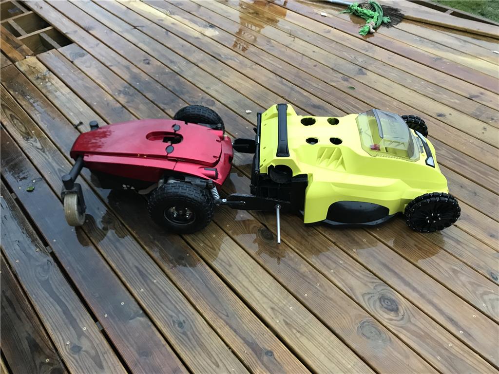
Ok so I am going to run over the general idea. I have been researching getting a robot mower and the options are sickly. They simply don't offer a full size electric robot mower for a reasonable price, at least for my pockets. :)
Welcome back. We missed your creativity!
Alan
Dito on what Alan just said. Welcome back. Your a creative genius and we need that around here.
Your back just in time for the new web site to launch in a few weeks and the new EZB release! These are happening times around here. Have you been peeking in and staying up to date or totally off in the real world this past year?
Good luck on the new project. Sounds very interesting. Are you building the platform from scratch or using your last Power Wheels car project to build this from?
Hey Guys ! I missed you! Yes I have been totally gone off the face of the earth lol. Once I started the new job it took some months to get oriented and settled in. It was basically like full time school. Anyways I haven't heard about the new ezb, and I haven't broken in my V4! wow. I applaud progress though!
So As far as chassis , I am considering using some parts from the truck project, but they may be too big. I will use different wheels likely for more grip , caster wheels in the front, and a chain drive to turn the wheels. I want to do that so I can keep the height adjustment. It would be awesome if I could put a servo or something on the height adjustment as well , how cool would it be to have those stripes like on a gold course! :)
Yes, You Have Been Missed ! Welcome back. Looking forward to you new endeavor.
Your project will cause much interest at my house. My 1/2 acre would be just the right size test site for this project.
Ron R
About time that you've returned :)
This is going to be a fun build to watch
Ok so here's the items I have on the way as we speak that will arrive either Monday or Tuesday.
Ok so list of stuff on the way so far..
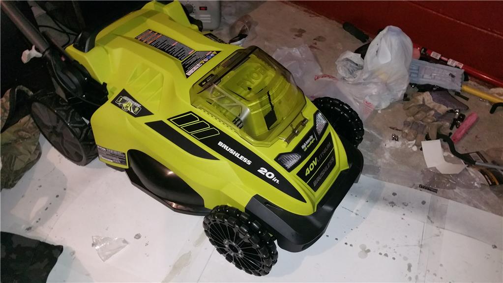
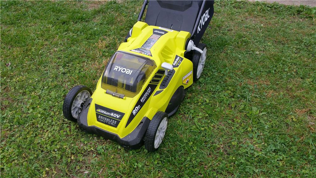
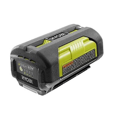
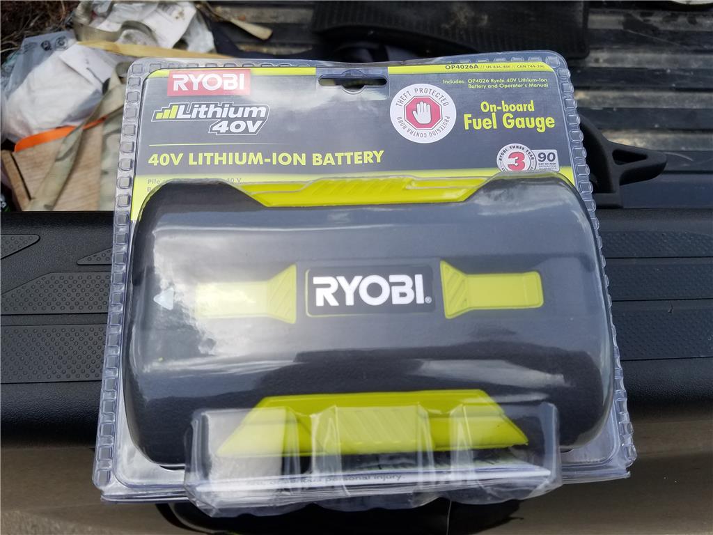
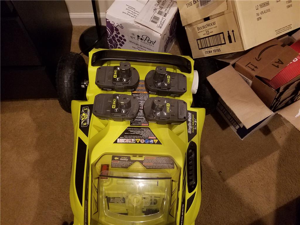
Ryobi 40v brushless lipo 2016 model mower $279.99 , batteries not included
Ryobi 40v lipo batteries x 2 $99.99 retail but both came with the trimmers at no additional cost
Ryobi 40v lipo string trimmer x 2 $149.99 retail amazon.com had it for $129.99 with a battery
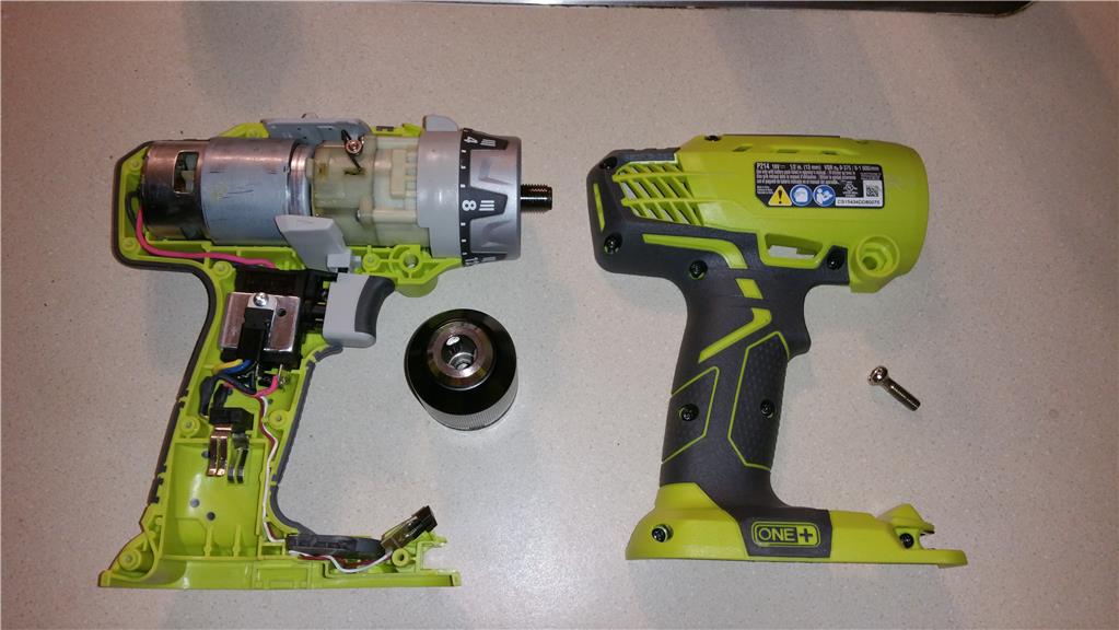
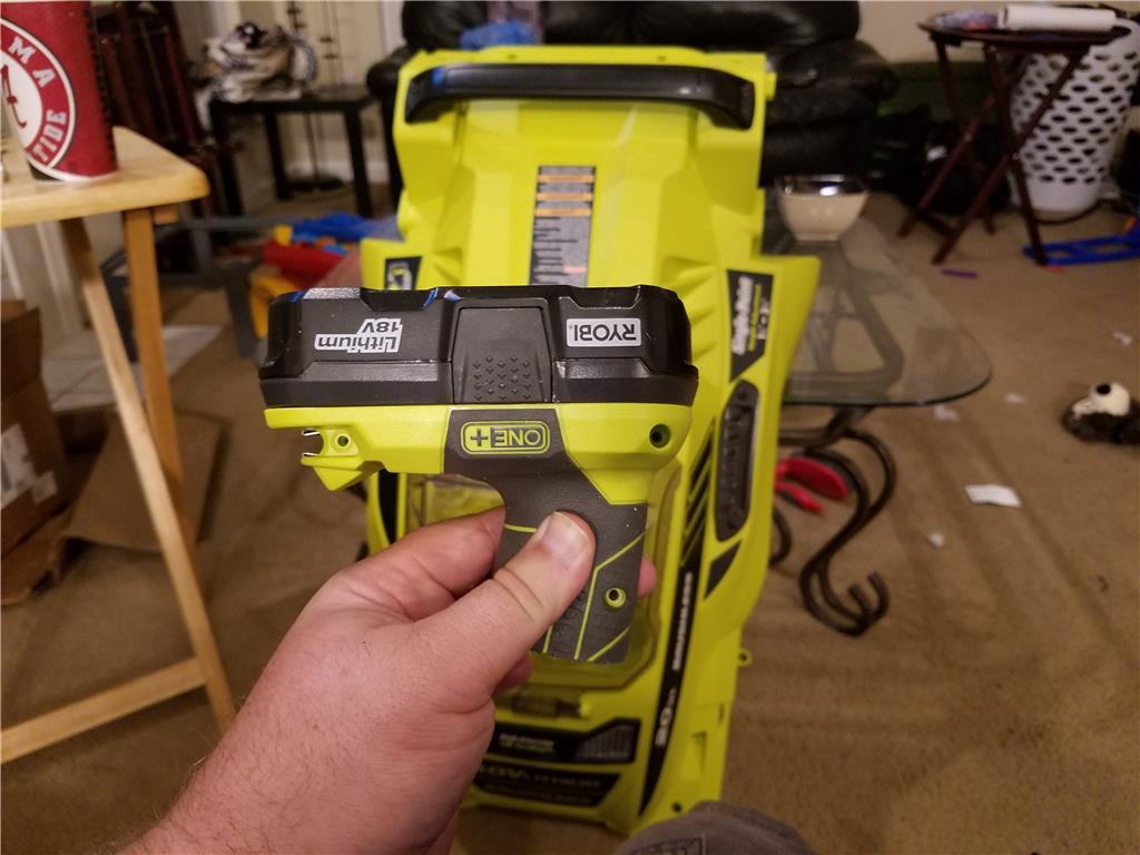
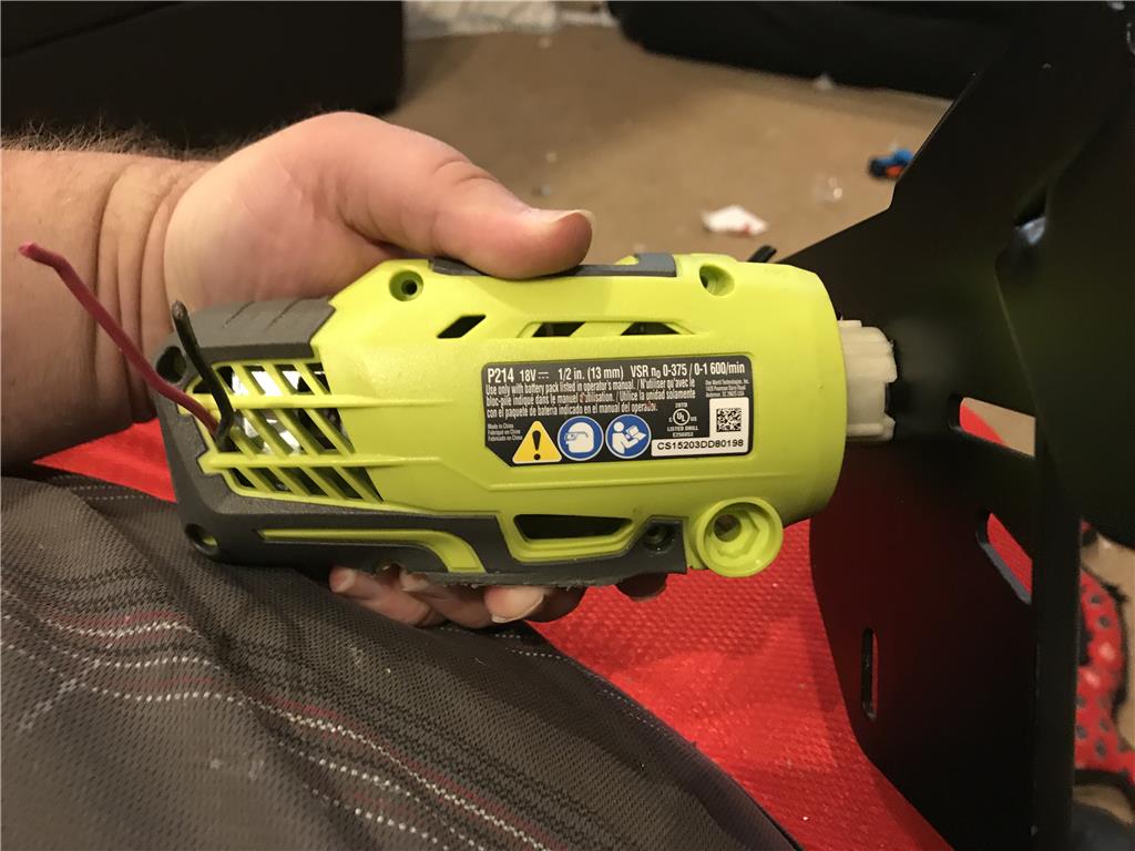
Ryobi 18v One + lipo electric drill x 2 99.99 retail, amazon.com $48 each
Zotac Pico mini PC usb powered 179.99
These are all on the way. I will list my other items as I either rob them from another project or order them. :)
This project is screaming for Robotzone servo Power Gearboxes!
HAHA, I already have two of them chilling somewhere I can use. I believe I have the 5 to 1 gear ratio , servo gearbox with 3 inch aluminum arms.
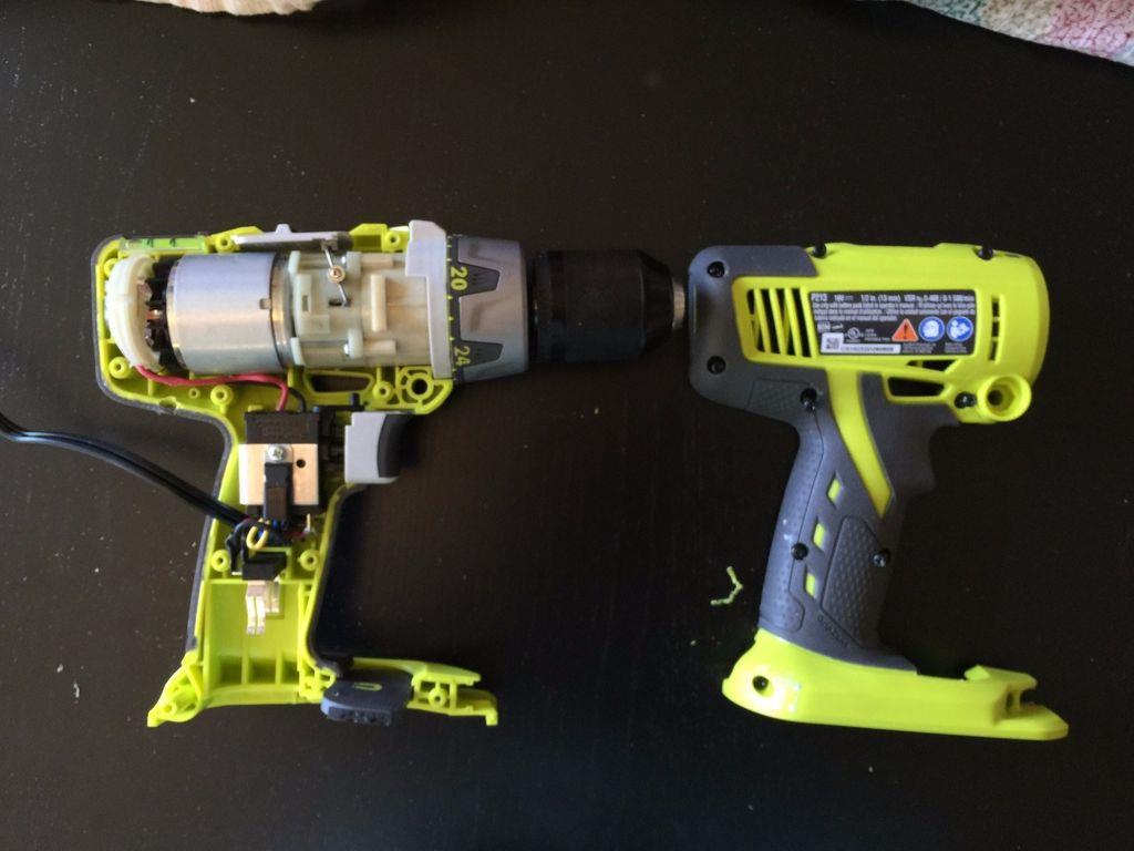
OK so I need a drive train. I am considering using the trucks power wheels gearboxes and then the hubs already connected to the wheel, I will just need to see how that fits. My second option which I believe is stronger and more reliable are two Ryobi Drill motors and gear boxes. I can connect a sprocket to the chuck and a sprocket to the wheel as a drive mechanism for each side.
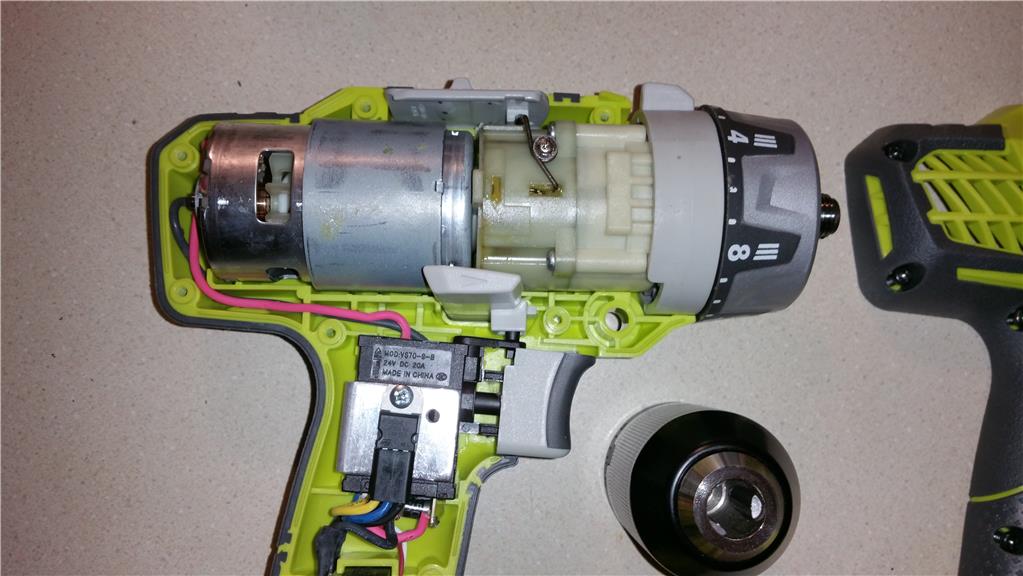
Inside this drill
Useing the drill motors is a fascinating idea. Cant wait to see how you work them into the drive train. Thous little motors sure are powerful. What voltage are the motors and what are you planning to supply to them? I imagine if they are 18v drills and you supply 12 that wouldn't hurt the motors, just slow them down a little.
Edit: Looking back at your shopping list I see you have 40v batteries and the drill motors are 18v. OK, then you can step down the 40v to 18. Any thoughts on what you plan to use to do that?
I have a couple options when it comes to lowering the input to voltage to the drill motors. First is using a voltage step down or buck converter. Second option - I am already going to need a motor controller (unless I used relays) , I can use PWM to lower the input voltage. The lower the PWM signal / duty cycle , the lower the effective voltage applied to the motors. I would clearly not have a PWM that allowed the voltage to go above what it was designed for. Most likely I would reduce voltage a couple volts to keep heat down.
Ok this step down converter with a claimed rating of 350 watts is on the way. Of course I probably wouldn't trust it past 200 watts. I have two on order that will be here in 7-10 days.
Module properties: non-isolated Adjustable Auto Buck Boost Converter(non-synchronous rectification) Input Voltage: DC10-50VOutput Voltage: DC10-50V(default 19V shipmet,adjust the blue adjustable resistance to change output voltage)Output Current:Max 20A(Because of the limitation of Max output power,the output current Max 20A)Output power: 350W Max Output voltage current LED meter display: Double four digital 0.28" tubeOutput voltage meter:Blue LED display 0-100VOutput current meter:Red LED display 0-20A Fan:DC 12V Double Ball Bearing Fan(The fan Automatic Control for Thermostat,Automatic start or stop)Operating temp:-40 ¡ãc +85 ¡ãc Input anti-reverse protection:Yes (can be long time to reverse,do not burn module)Output over voltage protection:No(output voltage exceeds 50V)Over temperature protection:YesDimensions:length 113mm x wide 78mm x high 56mm including the fan
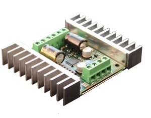
OK here is the proposed controller to run the two drill motors. I have one already on hand. If anyone has objections let me know. Thanks!
The Sabertooth 2X12 is one of the most versatile, efficient and easy to use dual motor drivers on the market. It is suitable for medium powered robots - up to 30lbs in combat or 100lbs for general purpose robotics.
Out of the box, the Sabertooth can supply two DC brushed motors with up to 12A each. Peak currents of 25A are achievable for a few seconds.
Overcurrent and thermal protection means you'll never have to worry about killing the driver with accidental stalls or by hooking up too big a motor.
Sabertooth allows you to control two motors with: analog voltage, radio control, serial and packetized serial. You can build many different robots of increasing complexity for years to come with a Sabertooth. Sabertooth has independent and speed+direction operating modes, making it the ideal driver for differential drive (tank style) robots and more.
The operating mode is set with the onboard DIP switches so there are no jumpers to lose. Sabertooth features screw terminal connectors - making it possible for you to build a robot without even soldering.
Sabertooth is the first synchronous regenerative motor driver in its class. The regenerative topology means that your batteries get recharged whenever you command your robot to slow down or reverse. Sabertooth also allows you to make very fast stops and reverses - giving your robot a quick and nimble edge.
Sabertooth has a built in 1A Switching 5V BEC that can provide power to a microcontroller or R/C receiver and a couple of servos. This built in BEC is almost identical in performance to our ParkBEC. The lithium cutoff mode allows Sabertooth to operate safely with lithium ion and lithium polymer battery packs - the highest energy density batteries available.
Sabertooth's transistors are switched at ultrasonic speeds (32kHz) for silent operation.
Solid choices. Hey, I have 4 or 5 (or more. I have to check) brand new Sabertooth 2x12 units. Two are slightly used. I switched all my Tooth's over to the 2x32 because I'm running my B9 off a power supply and they let me clamp the regeneration voltage instead of needing a voltage dump battery. If interested I'm willing to sell one or more to you for $60 USD each, plus postage. If you buy them all I'll ship free.
Let me know if you are interested. If not I'm putting them on ebay (someday,lol). :)
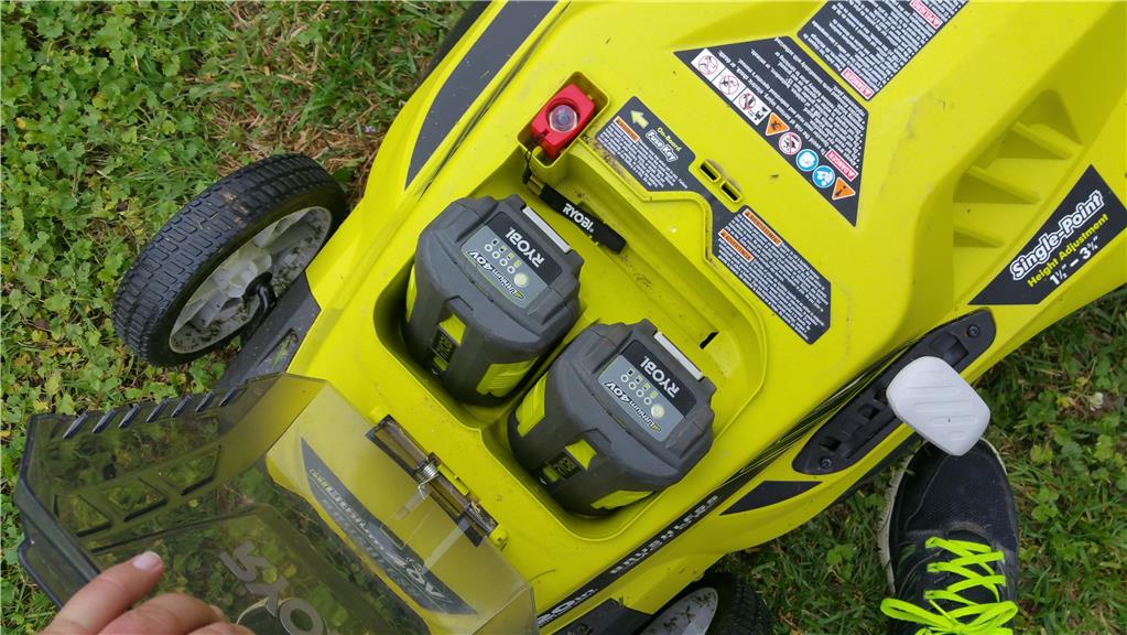
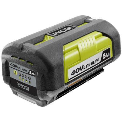
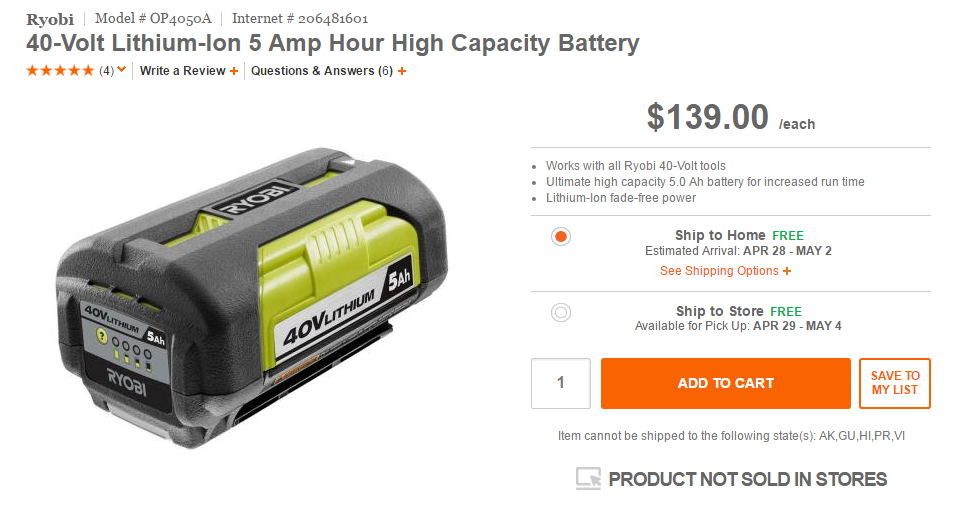
I realized the batteries that come with the weed trimmers are the "slim" batteries which are 1 ah @40v, These will be fine for testing during the build, but horrible for actual use. So instead I am going to search for the 5 AH version for a cheaper price on ebay but if I cannot get one for less than 60 or 70 I will just buy it new because they come with a automatic 5 yr warranty against charge fade from Ryobi and Home Depot.
I cant afford to buy a couple now but maybe next month after the bills are clear. I probably wont be ready for actual usage by then so that's OK.
Hey Dave , I would love to get some from you. That's a good price and would help the project.
Cool, just let me know how many you want. I just checked and I have only four available. Thought I had more. Please contact me off the forum at dschulpius at gmail dot com and we'll work out the details. Thanks! :)
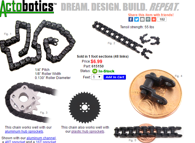
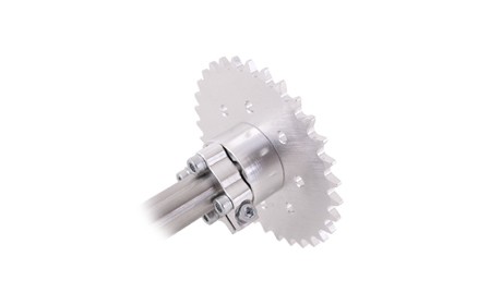
Servo City order, I plan to use sprockets and chain to transfer torque from the drill gearbox to the hub of the rear drive wheels. They are good for 55 pound working load in either direction according to servo city. I chose these over the metal because they are easier to adjust and disassemble and this robot will only weight 60-80 pounds.
2 (RHS-250-16) 16 Tooth Hub Mount $5.64 $11.28 Sprocket (.250 inch) * Weight: 0.01 lbs. each
2 (RHS-250-48) 48 Tooth Hub Mount $8.20 $16.40 Sprocket (.250 inch) * Weight: 0.01 lbs. each
6 (615150) 0.250 inch Plastic Chain (48 $6.99 $41.94 Links/package) * Weight: 0.02 lbs. each
My order is on the way and will be received in 3-4 days by USPS
I love Servocity! They have such cool and imaginative stuff.
Yes they are a great supplier! They are not cheap but are not out of this world on pricing either. They have a happy medium.
I think I have bought 4 gearboxes from them and other misc stuff that was useful.
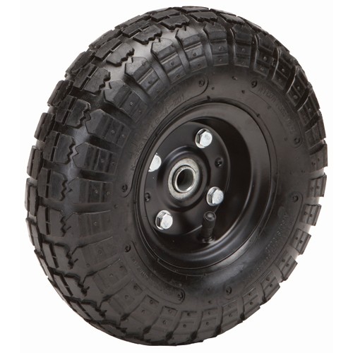
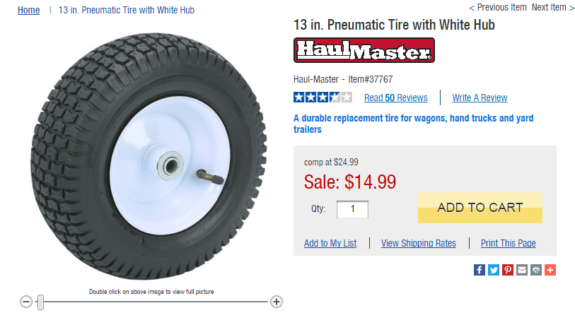
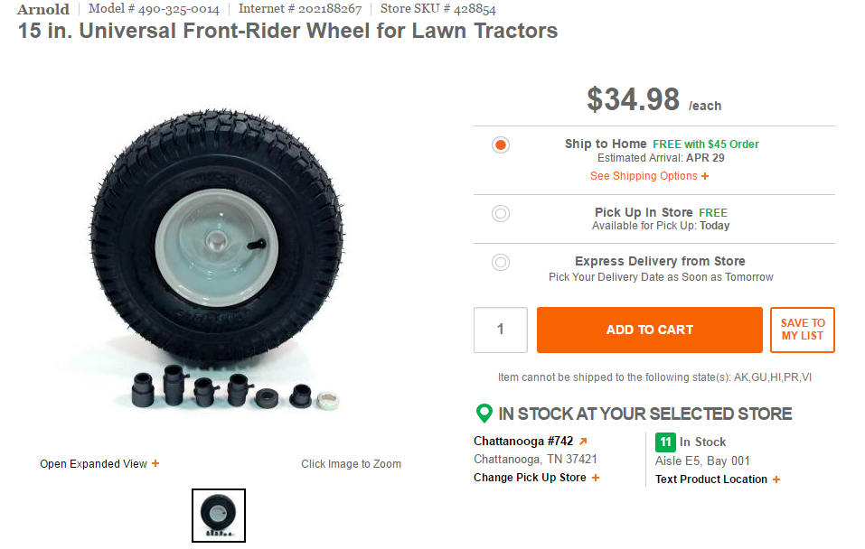
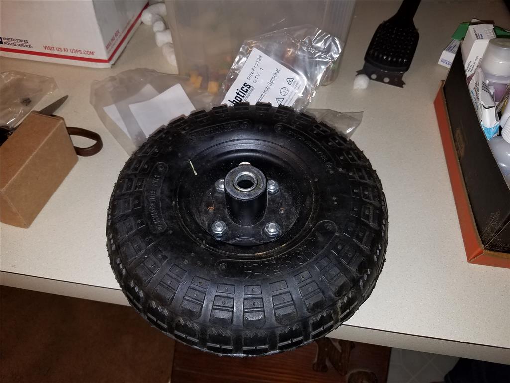
OK I already have some 15 x 6 in Arnold Turf saver lawn tires but I am concerned they are too big to fit. So I took advantage of a sale at Harbor freight and picked up 13 in x 5 Haulmaster tires. I got them for 12.99 and an additional 20 percent off with a coupon. If they fit the mower well then I will drill holes and put on some kind of home made adapter to mount the chain sprocket to.
I have 4 of these Arnold tires. They have the same tread pattern but the tread is deeper and this wheel is 1 inch wider that the cheaper wheel. Also the Arnold ( Carlisle rubber) is a smooth grease bearing only which is messy. The Haulmaster has a cheap ball bearing, but ball bearing non the less so I wont need to lube it.
Though the Arnold certainly would offer a bit more grip I am leaning towards the smaller wheel. Any input guys? thanks
Good luck with your lawn mower project. I built an EZBv4 version about a year ago. synthiam.com/Community/Questions/8102
For safety reasons I chose to use trimmer heads rather than a steel blade. Chain and sprockets work well, but tend to get clogged with grass clippings. Instead I opted for sealed planetary transmissions. I've since upgraded mine to four wheel drive with 8" diameter pneumatic tires for better performance. I have some other improvements planned when I can find the time. I'll be following your progress.
Jim
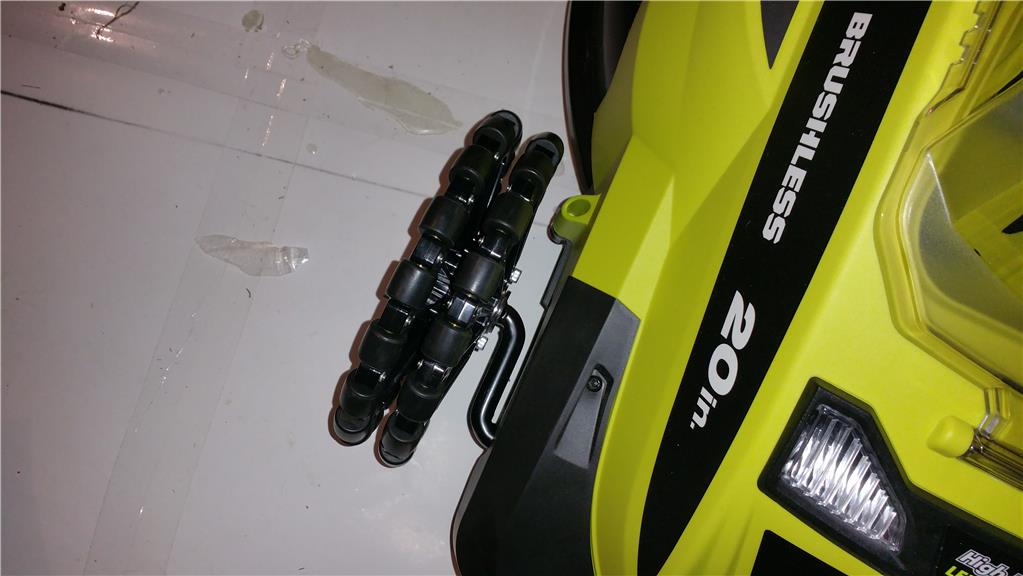
Thank you for the suggestions. I also plan to use trimmer heads to " precut" the higher grass and I believe I will mount them on the front corners so they act like roomba whiskers trimming close to objects.
The chains are only for driving the rear wheels and motors will be mounted above the rear wheels at the highest point away from the ground to try and avoid sucking in grass or whatever since they are air cooled. The trimmer motors and main mower head is the normal one that comes with the donor mower I am using to start with.
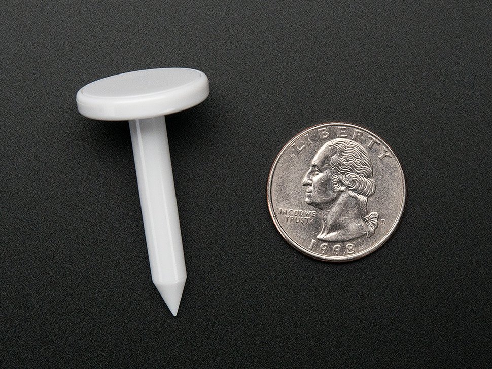
So I an brainstorming options for yard location orientation. I am considering using RFID stakes in the soil with a antenna pointed at the ground to read them. This way not only can I create a invisible border around my property but I can also mark areas like a charger station , flower bed or anything else needing to be marked.
$2.36 each for 100
https://www.adafruit.com/products/1483
Please share your opinions and suggestions, it helps the creative process.
OK tiny update, the mower arrived last night but I have not unpacked it yet because there is no battery to test it with. I will have the small 1 ah batteries that will come with the weed eaters tomorrow, but I really need a couple ( if not 4) batteries with balls. I ordered one 40v 5ah capacity Ryobi for 139.99 with free shipping. I would have built my own packs but they would have been just as much ( realistically more) to build than buy this part, so I went OEM. plus I get a automatic 5 yr warranty and an additional 3 if I register them online. I could only swing 1 battery this week but in a couple weeks I can grab another and I will update everyone on the collection of equipment as this moves forward.
Tiny update on shipments: The 40v weed trimmers and the standard sized 40v batteries have arrived. I haven't unboxed everything yet but I will take some snapshots when I do. Also the servo city order arrived for the sprockets and chains to connect the drive motors ( gears) to the hub of the wheels. As for the 5ah extended capacity 40v battery I ordered, it does not show shipped yet, but I look forward to having it by Tuesday next week.
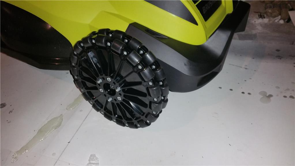
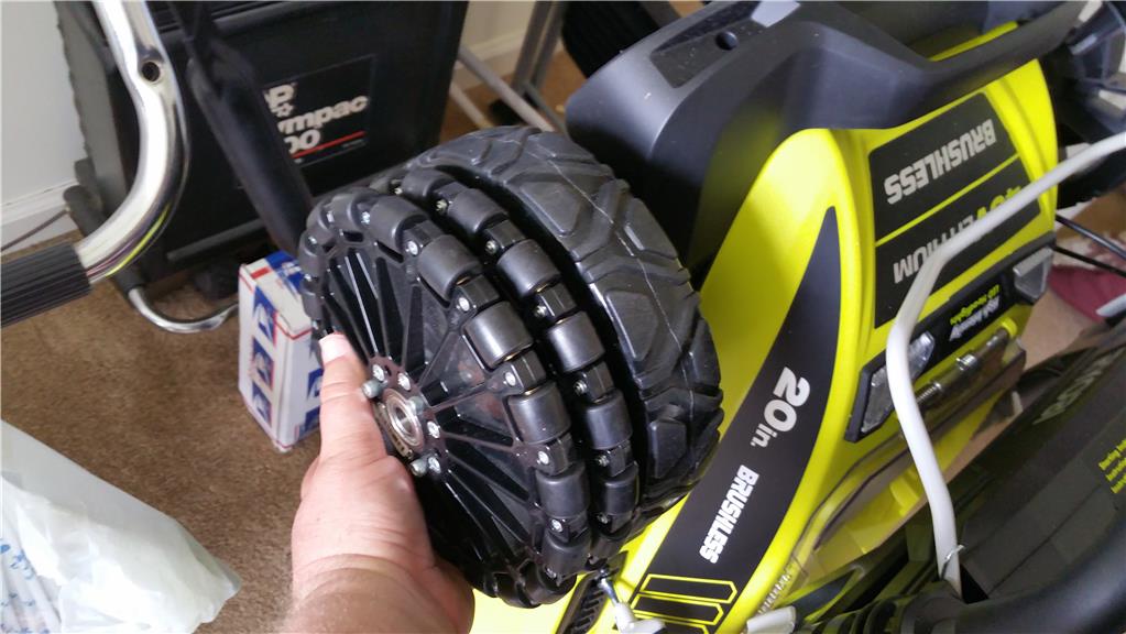
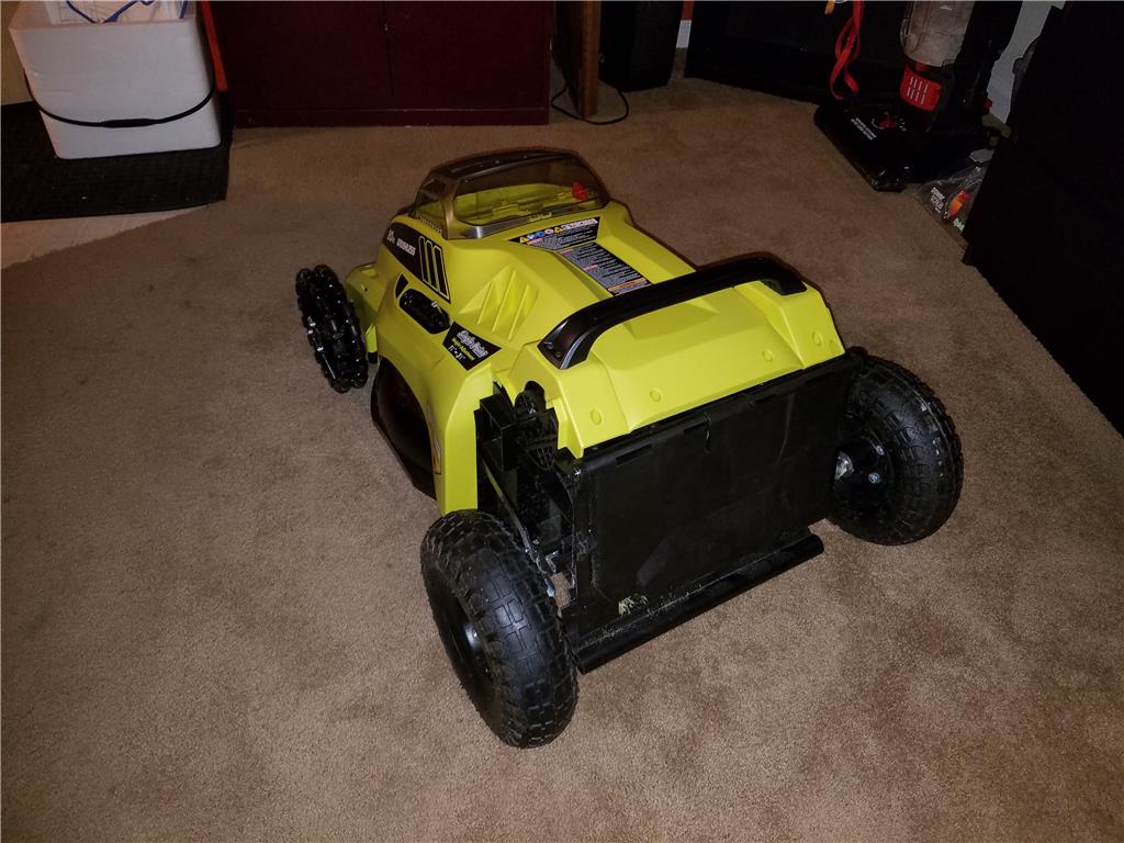
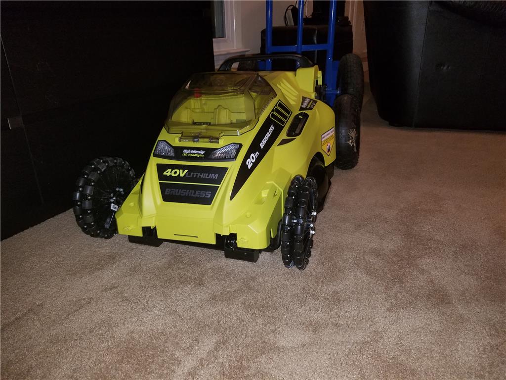
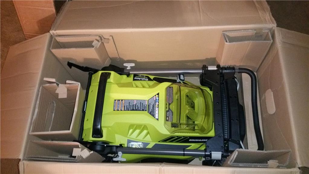
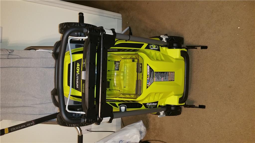
Ok so I unboxed the lawn mower which is beautiful by the way. Now that I am looking at the mechanisms for height adjustment I would really like to keep it. It's just so easy to use ! So that means casters for the front are probably out. The next solution is to replace the front wheel with a 8 inch diameter omniwheel. I would print this but that is bigger that my print bed. Unless I can chop up a file. I also realized I bought a couple gears I potentially could have printed... shrug.. these are solid so that's a plus.
I particularly like this stand up feature , I will see if this is something I can keep when I disect the handles and frame away from the mower body.
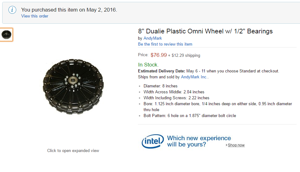
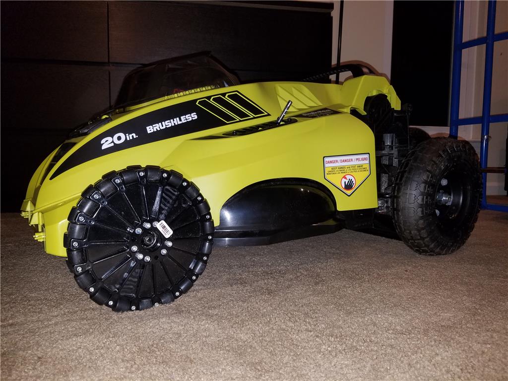
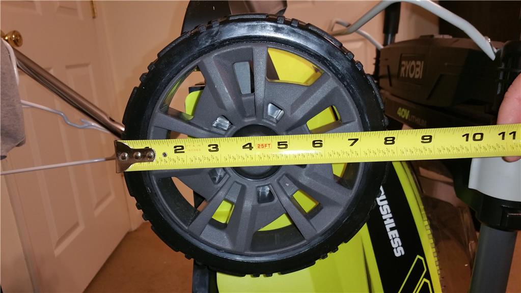
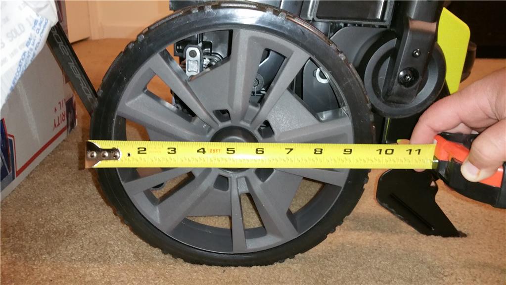
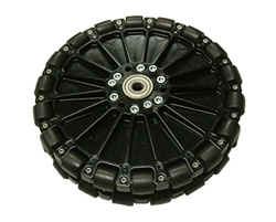
I measured out the wheels. Like I thought they are not the sizes that the website says. They are off by an inch. So I need two things. First is a set of rear wheels with enough grip to drive the mower and front wheels that can roll side to side. That means I need an 8 inch set of omniwheel to let this guys front end slide left to right for east turning.
8" Dualie Plastic Omni Wheel
Specifications: Diameter: 8 inches Width Across Middle: 2.04 inches Width Including Screws: 2.22 inches Bore: 1.125 inch diameter bore, 1/4 inches deep on either side, 0.95 inch diameter thru hole Bolt Pattern: 6 hole on a 1.875" diameter bolt circle Body Material: Black Polycarbonate Load Capacity: 120 pounds (rollers don't spin pas this weight) Weight:2.2 pounds Number of Rollers: 36 Roller Material: Black SBR Rubber Roller Durometer: 80A Roller Bearing Material: Brass Roller Axle: Steel Dowel Pin Roller Diameter: 3/4 inch Repairable by removing interior #10-32 screws and perimeter M3 screws Included Hardware: Four - 8" Plastic Omni Wheel Webs Thirty-Six - Black SBR Rollers Thirty-Six - 1x1/8 Steel Dowel Pins Sixty-Four - Omni-roller Sleeves Nine - Individual M5x0.8 x 20mm SHCS Twelve - Individual M5 Nylock Nuts Three - Individual #10-32 x 2-1/4" SHCS Thirty-Six - Individual M3 Nylock Nuts Thirty-Six - Individual M3 x 10mm SHCS Three - 1614ZZ 3/8" id Bearings
$74 plus shipping
Here is an 8 inch omniwheel from andymark.com , does anyone know of a better price from another dealer?
Ok I ordered two Dualie 8 inch omniwheel for the front of the mower. They should be here from the 3rd to the 5th.
Vex Robotics makes some nice dual omni wheels.
www.vexrobotics.com/vexpro/motion/wheels-and-hubs/omni-wheels.html
JIm
Oh wow , thanks Jim , I will take a look for sure.
Ok Andymark Inc was super cooperative in getting these large 8 inch omniwheels to me quickly. They also got me a better deal than the wheels I bought on Amazon to begin with and saved 20-30 dollars and also pressed in 1/2" ball bearings as well. Originally only the single 8 inch wheel was avail through amazon so they really did me a solid.
TINY update , so after some measuring I am leaning towards "whiskers" being a different robot all together to keep things from getting too big. To get the trimmers on the mower I would need to lose the height adjustment as well as I would need to keep the height about 3 inches for the trimmer heads to clear the ground. So between those two I chose to make the trimmer bot the second chapter of the build and the mower is the first. KISS method , they say. Keep it simple stupid...
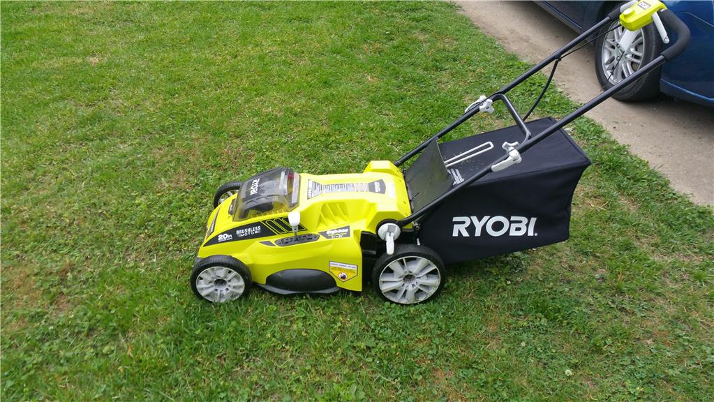
That being said I went to return my junk electric mower because it was within the return period. And exchanged it for another ryobi mower very similar to the first one I bought and managed to get two 40v batteries and an additional 40v charger too! All for 149.99. Online that's a 499 bundle just to clarify. So I will use this used mower as the chassis for the second bot... the trimmer that follows the edges of the lawn.
OK here is the very similar used mower I picked up from homedepot. I used it to mow the front and sides of my lawn. It's last year's model vs this years. Very minor changes but a great deal for a robot chassis complete with batteries and charger.
Wow! Where are you finding these for that price? I would get one just as a mower let alone as a robot. In fact, I think the batteries are more than that retail.
Alan
I order then online , I just returned a accidental double order. The 16 inch version is 149. The batteries can be bought for 57 dollars each on ebay as reconditioned from product returns. I have 4 , 40v batteries.
It is good to see you building again my friend.... I will be following this one closely.
Thanks Rgordon!
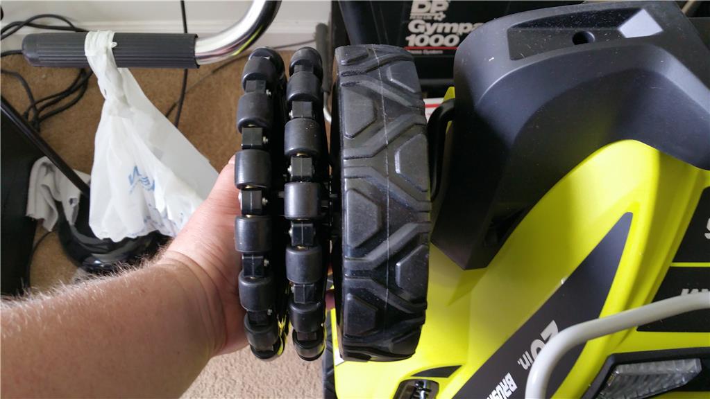
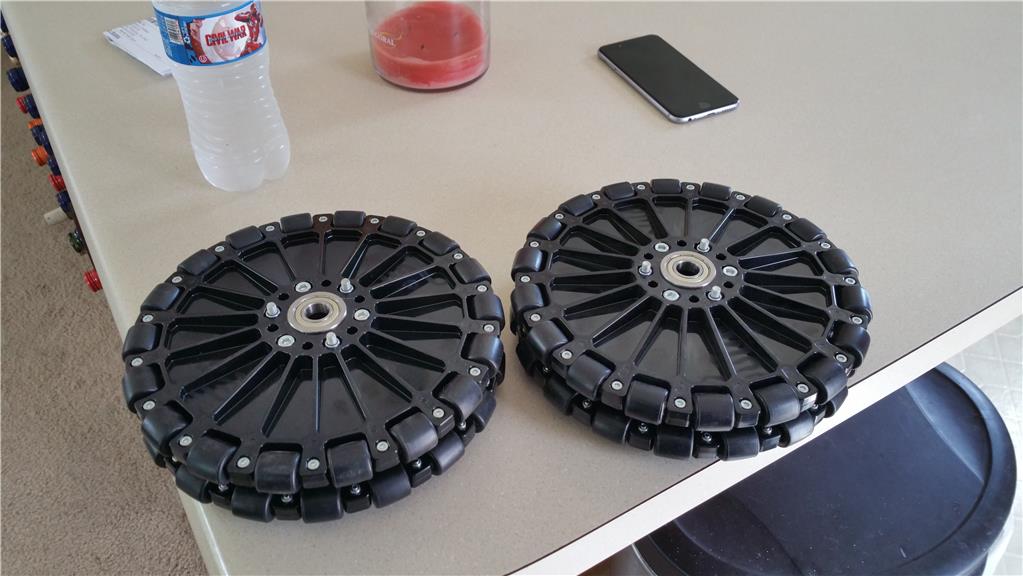
Ok as promised Andymark wheels arrived very quick. I was eager to unpack them and compare the to the wheels they intend on replacing on the robot mower. Spot on !
My only concern is the thickness of the bearing. We will see if I need to modify anything to get it to fit snug without wobble as this has ball bearings.
Ok I've been working on making a really big back deck , so now that rain is moving in I will move back to robots. I tried slipping the bearings onto the axle shafts and they do not fit I believe that the powder coating of the axle has made the thickness a little more that 1/2" thick. I will probably pull out a sander and remove the coating so I can get these wheels on tonight.
I am curious about how the Omni wheels will work on the lawn. Even though I have some concerns, it is a great idea. It is great to follow your projects again. Your neat ideas have been missed.
Thanks for sharing,
Ron
Thanks Andy! I see many other robot mowers not even bother with changing the front wheels. They just let them drag like a skid steer system. Though mine isn't much different I would feel it is a sin to drag things around lol. Anyways after minimal modification of the powder coating on the axles , the ball bearing sets I ordered now fit. I sanded the shaft down with a electric palm sander (ryobi ofcourse) with a 60 grit pad. I may try a retrofit onto the back wheels as well since these are so nice. I only had room for 3 of the 4 sets of bearings. I had to pop the outer bearing out. They are on snug ,but spin freely without any side to side wobble on the shaft.
Just in case anyone is just now tuning in , I used the original axles because they have a mechanism I can utilize to adjust the height and keep the mower level at the same time. It could all be done with one servo or linear actuator.
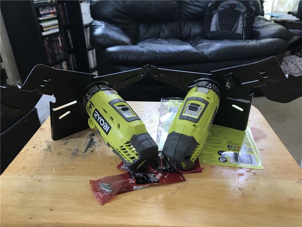
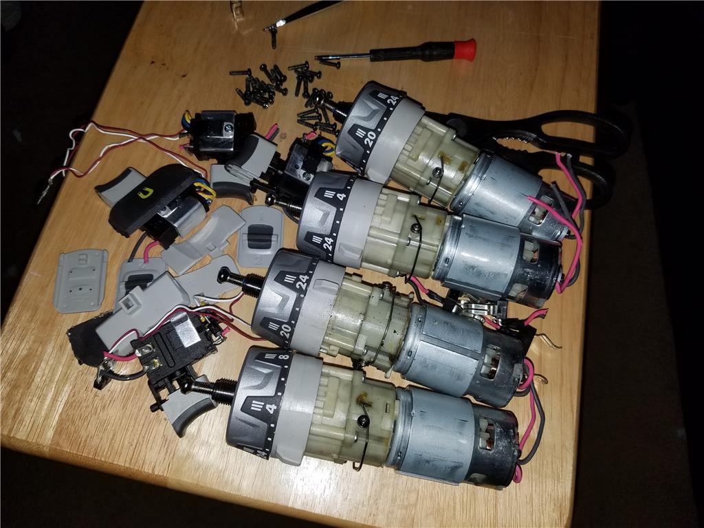
Ok tiny update , the new set of 600 Oz in Hammer drills arrived. I think I bought this set through Amazon for 42 dollars each. Great price for a brand new motor and gearbox. If you keep the clutch you can prevent stalling if you exceed the torque rating too.
Ok so I was thinking about batteries and such. If I have drill batteries to power most the robot except the main drive motor then I will need a way to disconnect and swap them easily. The batteries come with a 5 year warranty if you register them so that's a thing. I did find out for other robots in the future that Rigid has a lifetime warrange on batteries. So if you ever need a battery for a project you can replace forever.... that's an option.
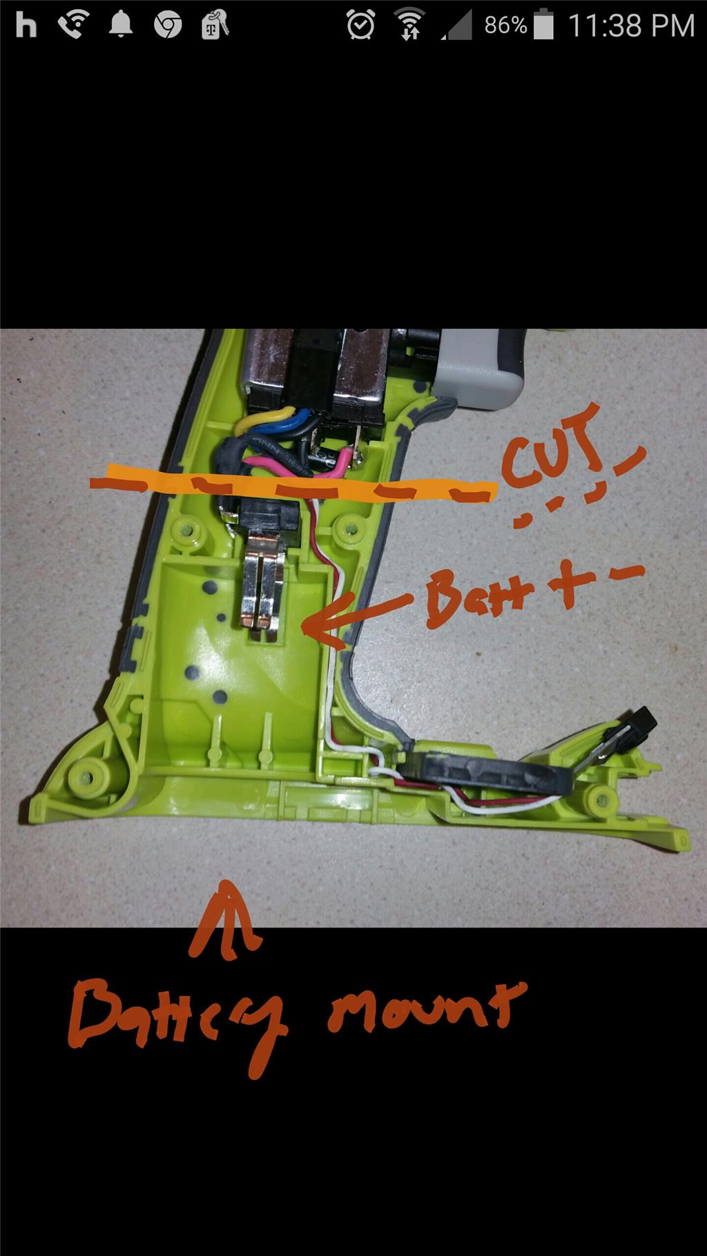
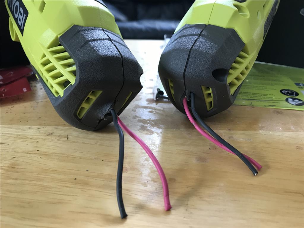
The case for this drill will not be wasted. The top half I can utilize as a sort of mount and the bottom half of the handle I will cut off just above the screws so that I can make battery mounts for them on the robot. I'm still contemplating where they will go. First place that comes to mind is the top of the robot facing down the next is to try and hide them under the shell somehow with a pigtail for charging until I get this thing a dock.
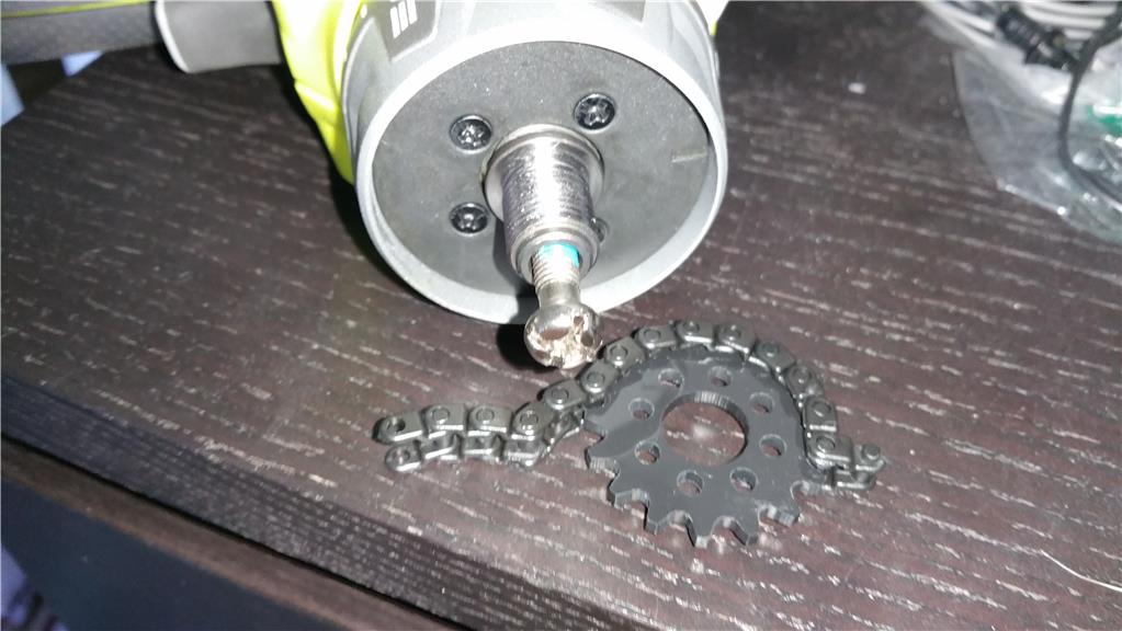
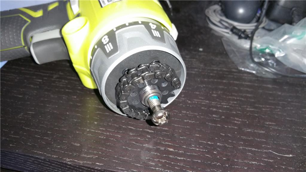
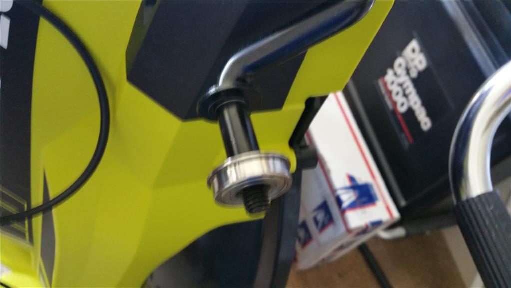
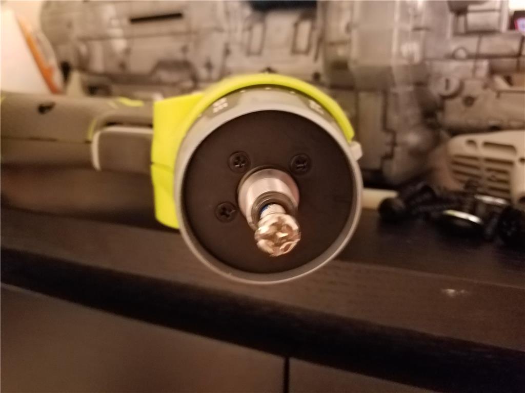
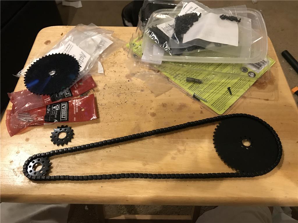
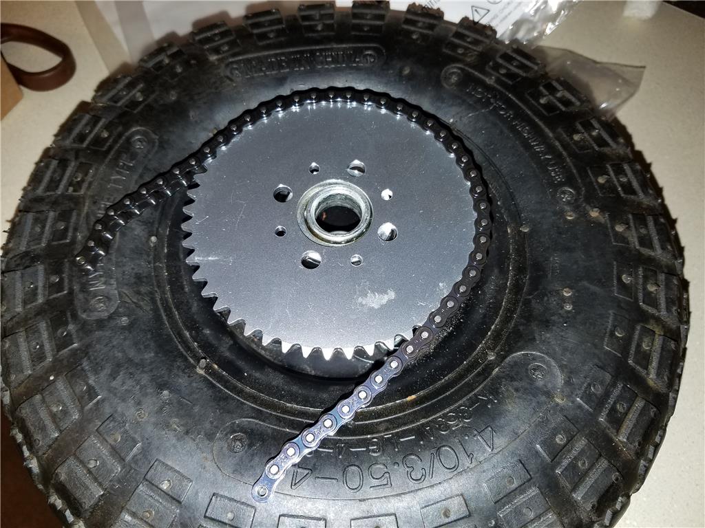
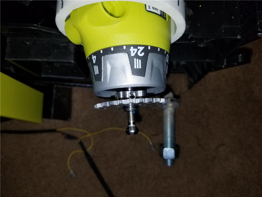
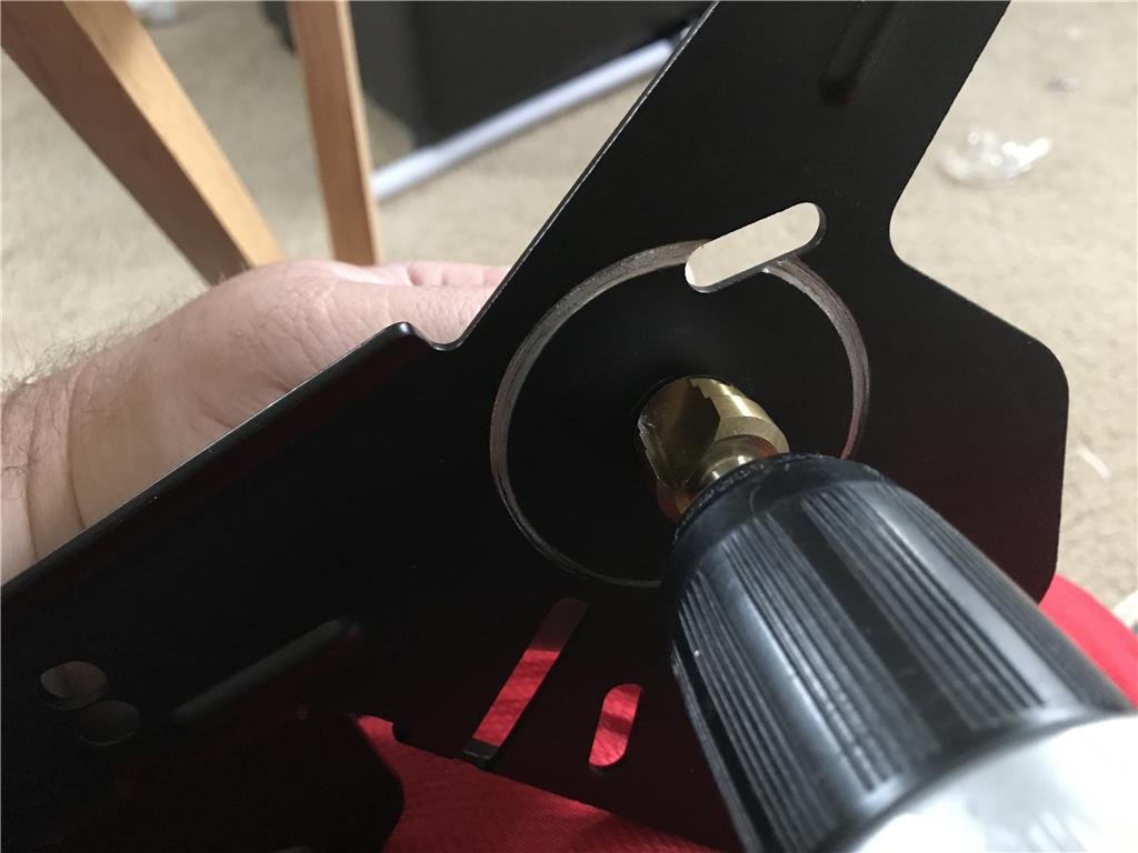
Here is the plastic chain cable with the plastic sprocket. I may upgrade to aluminum sprocket and and metal chain if this is not strong enough. Breaking strength of the plastic is 50 pounds. Looks like all I need is a couple washers , lock nut and regular nut to lock the pocket onto the motor shaft of the drill.
Today I had the chance to try out the mower on grass with the omniwheels on the front. I had some level of concerns that the wheels may somehow snag on uneven ground. They performed far beyond my expectation to the point I feel all lawn mowers should have omniwheels on the front ! I need to market these things! lol. Anyways the next step is to swap the read wheels out and set bearings. The hurdle here is that the shaft is only 1/2 inch but I an supposed to use 5/8 " bearings in diameter with the tires I bought.
I'm enjoying your project. Coming along nicely. I was also wondering how the Omniwheel would work on grass. Glad it worked.
Do you think you'll have it ready before the end of the grass growing session?
I also don't have anything to add other than - way to go! This is fun to watch
Hello all , yes I believe I can have something rolling around soon. It was mostly a matter of buying all the parts and now I can disassemble the mower and see what position I want to mount the motors in so the chain can wrap around a sprocket to turn the wheel.
Hello @jstarne1,
Excitement is growing. I am looking forward to see how the drive system ends up. I am sure the motor mounting and sprockets is a challenge. It will be doing a lot of work and needs to be strong. Looking forward to seeing your next post.
Ron
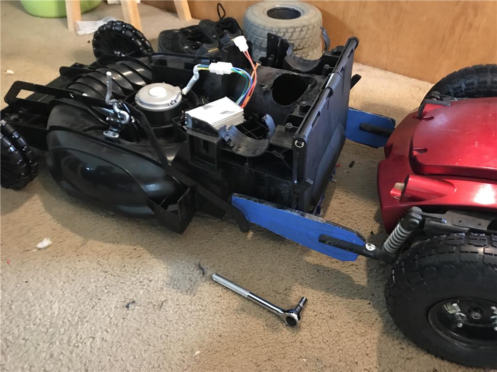
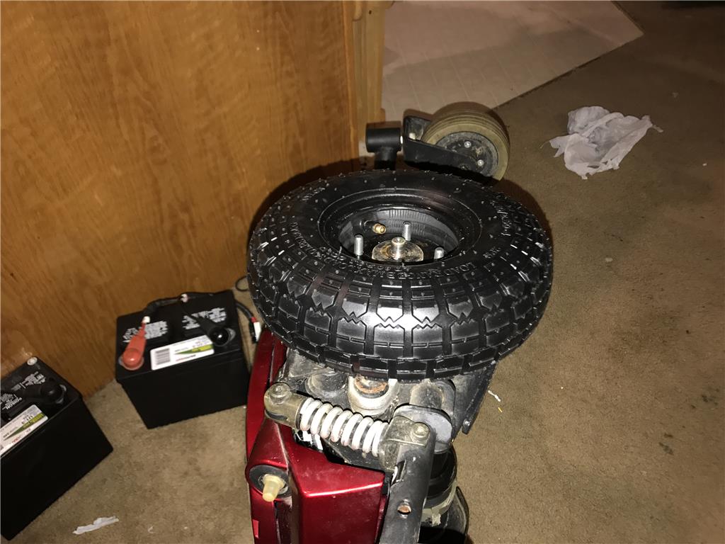
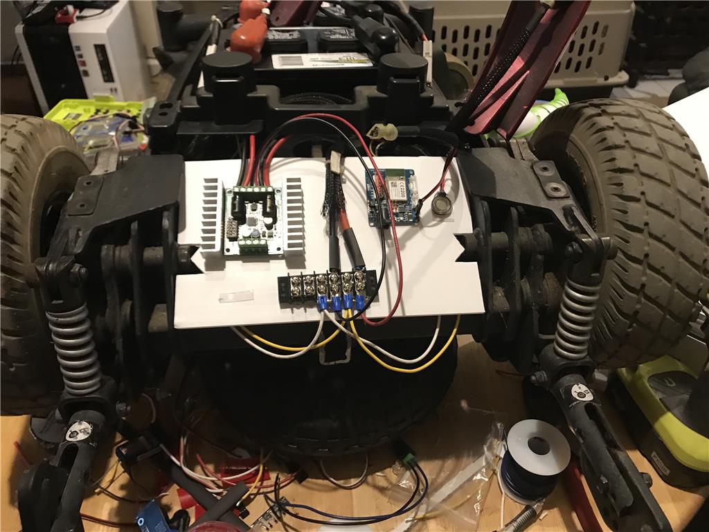
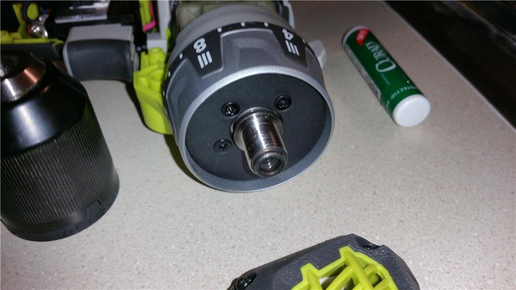
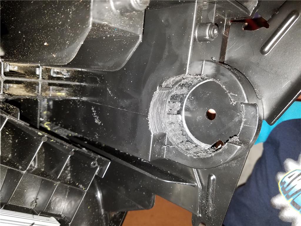
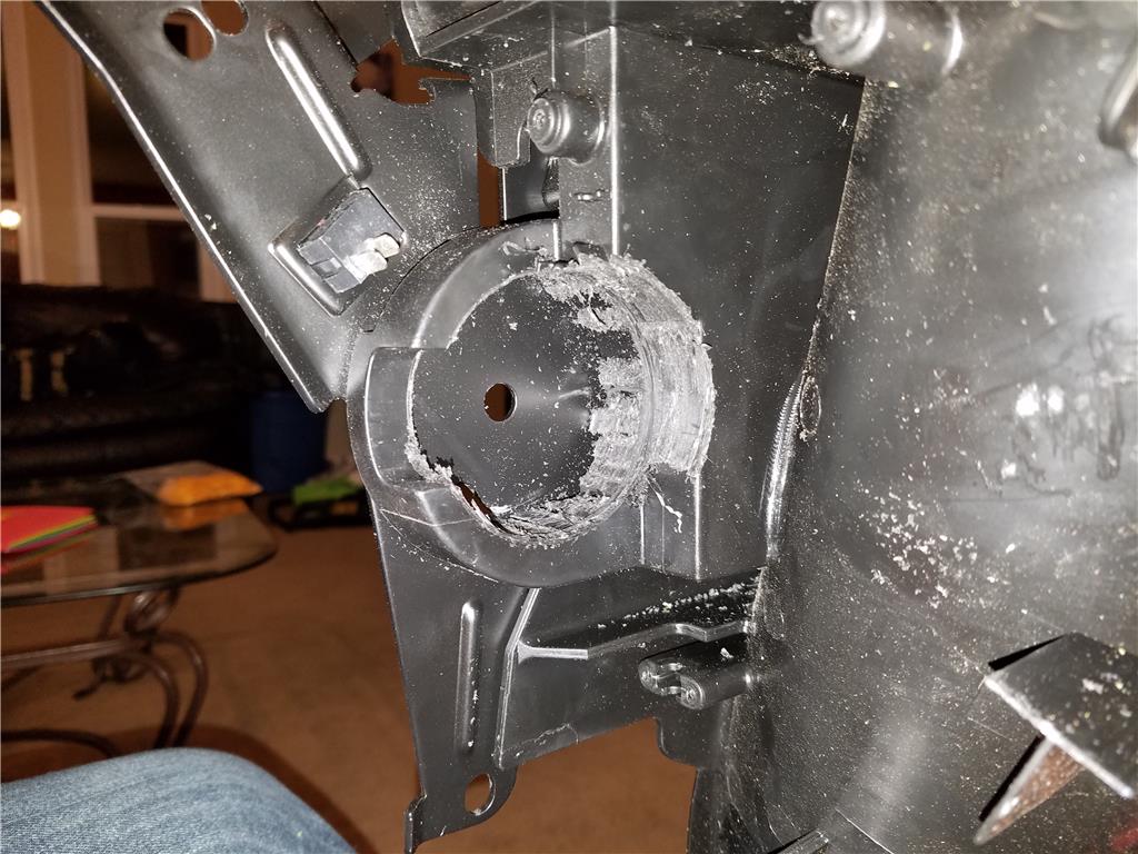
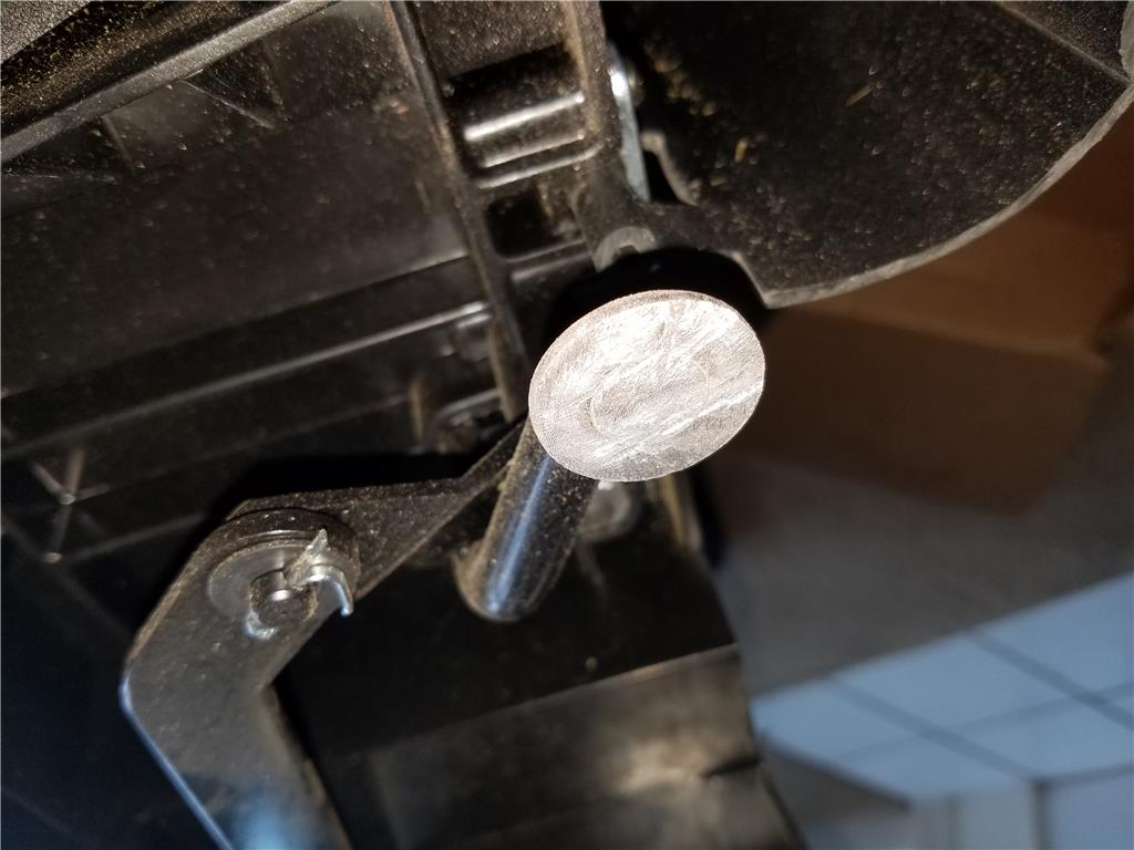
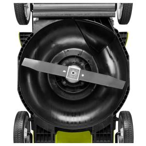
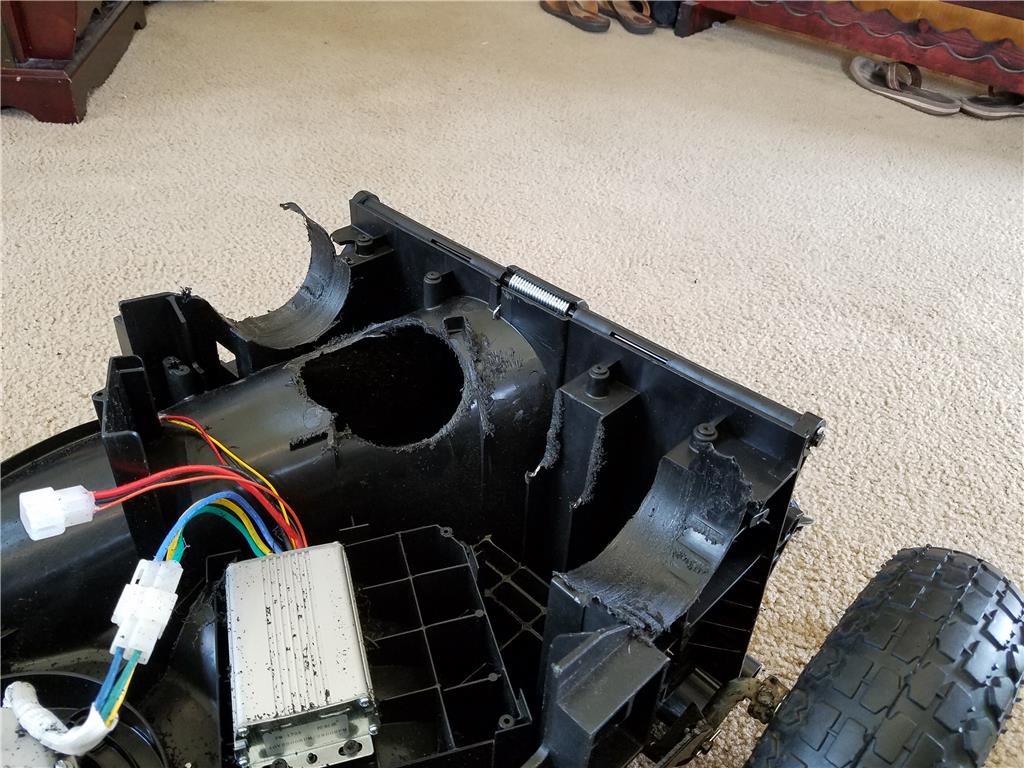
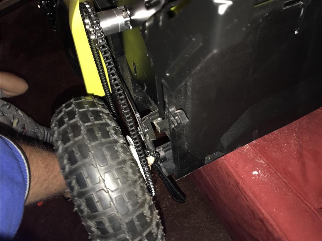
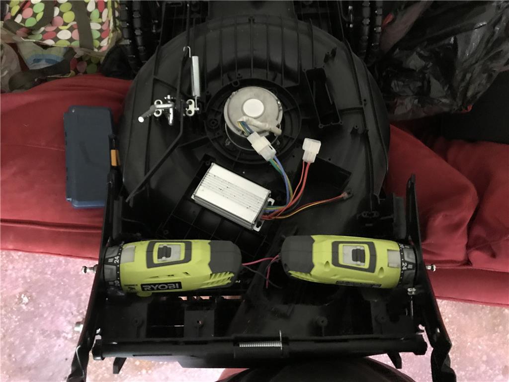
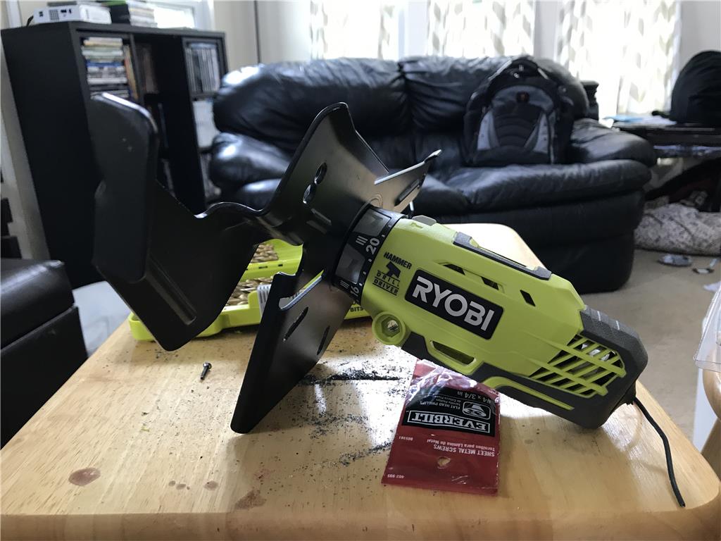
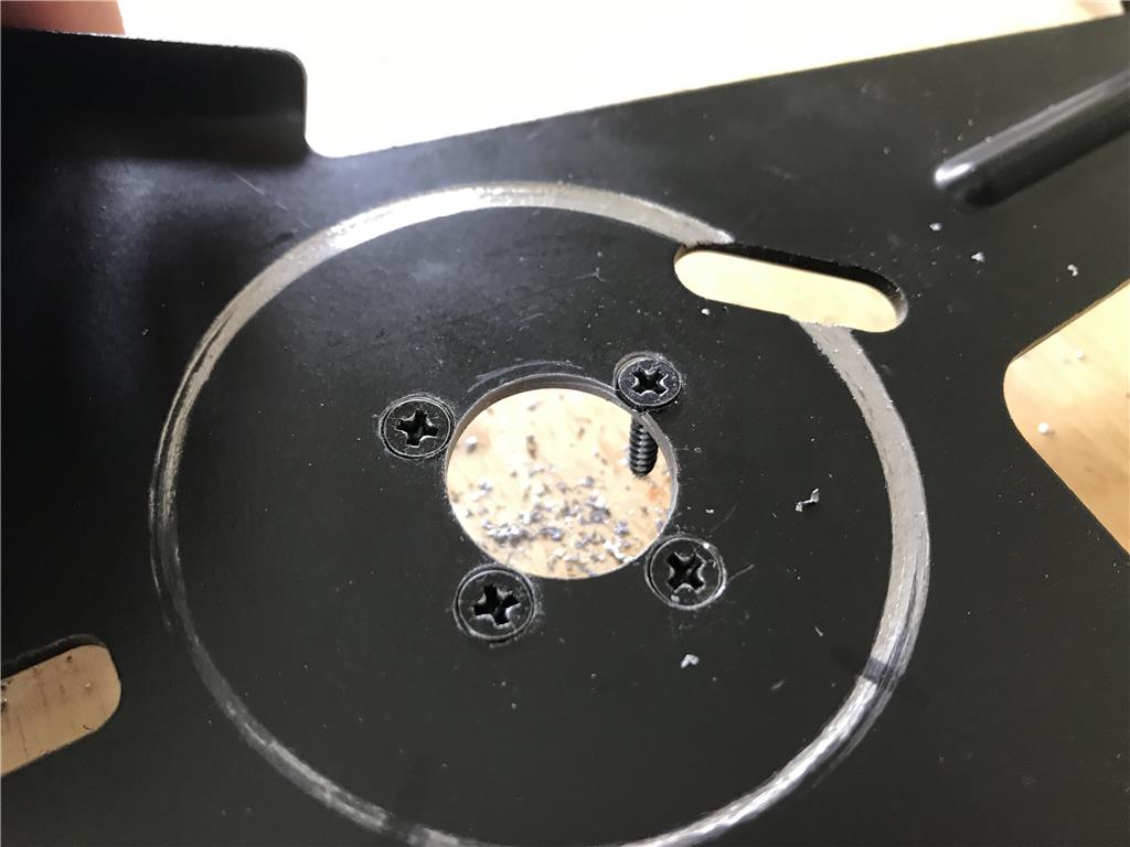
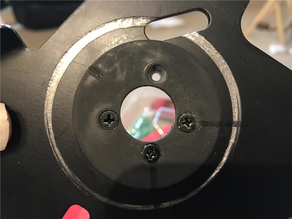
Ok I managed to get an off day tomorrow so I am not concerned about waking up too early. I started taking the mower apart. Considering it is 80 percent plastic there are many metal brackets and large solid bolts holding this together. The good news however is that these large metal brackets give me the opportunity to mount the drive motors to a particularly sturdy part of the frame. Here is a pic for reference. I may just lock the clutch with set screws and use the 4 screws in the end as a mounting point.
Hope you get some sleep in the morning.
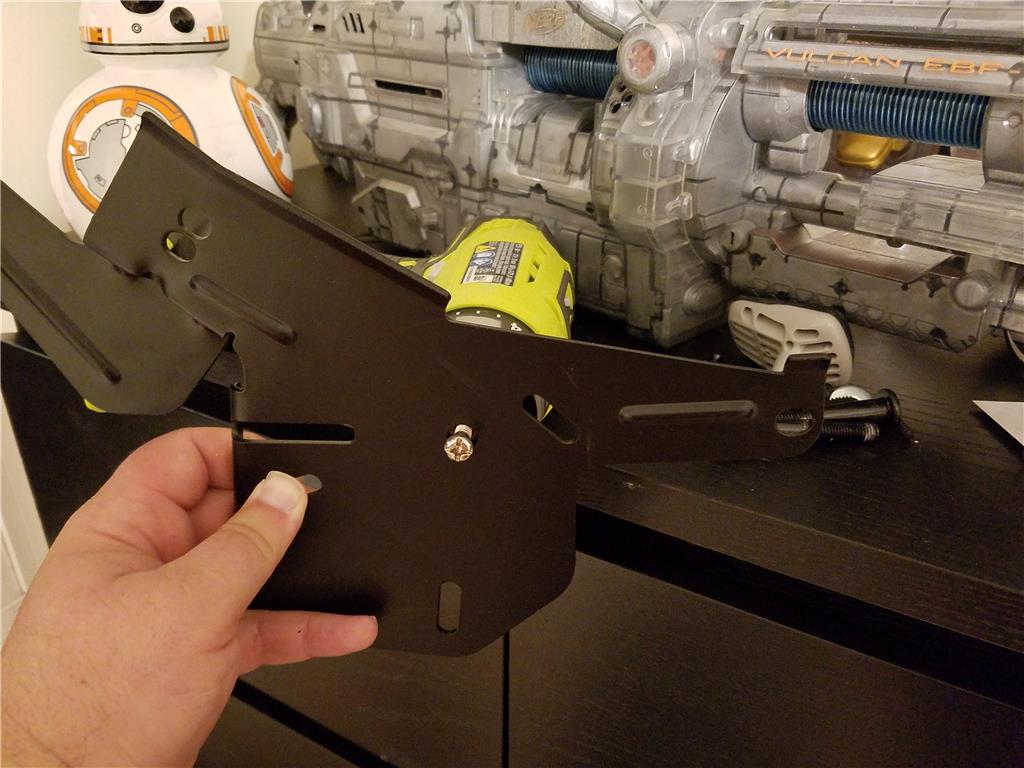
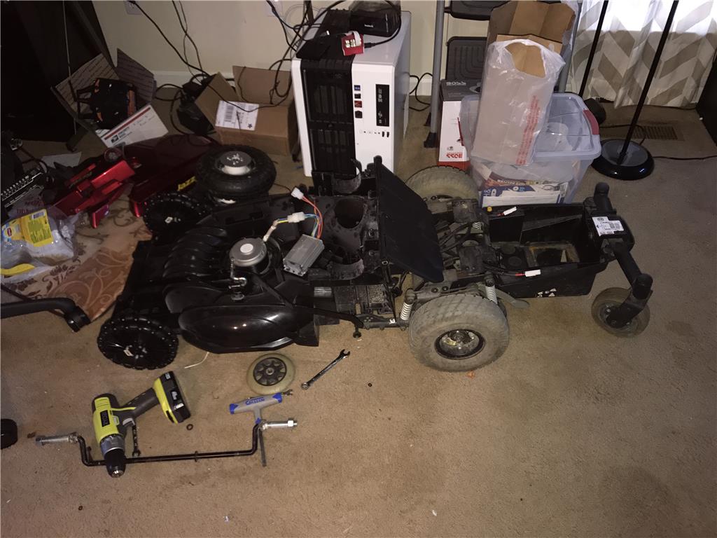
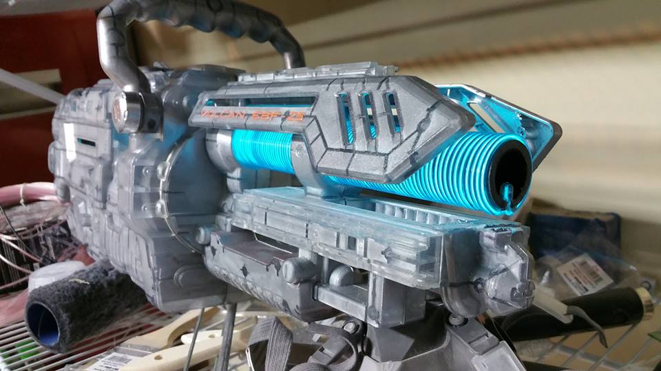
Dude, is that a modified nerf rifle in the background? Bad to the bone. cool
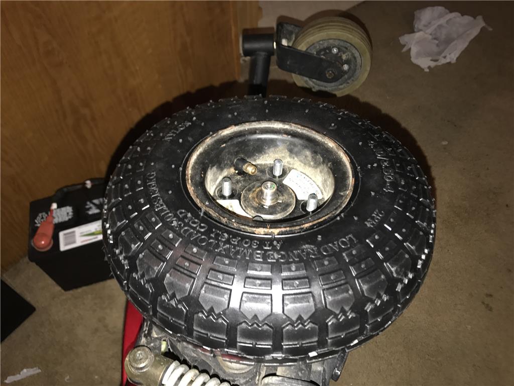
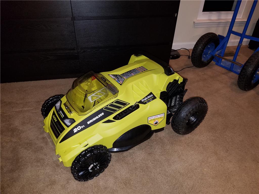
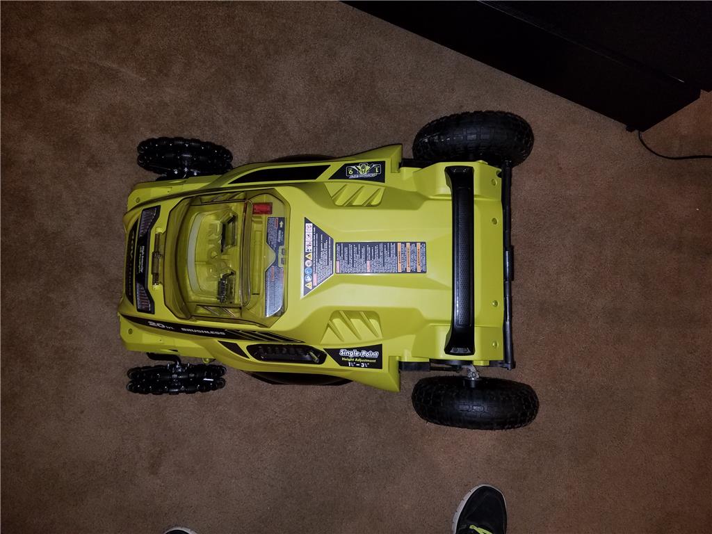
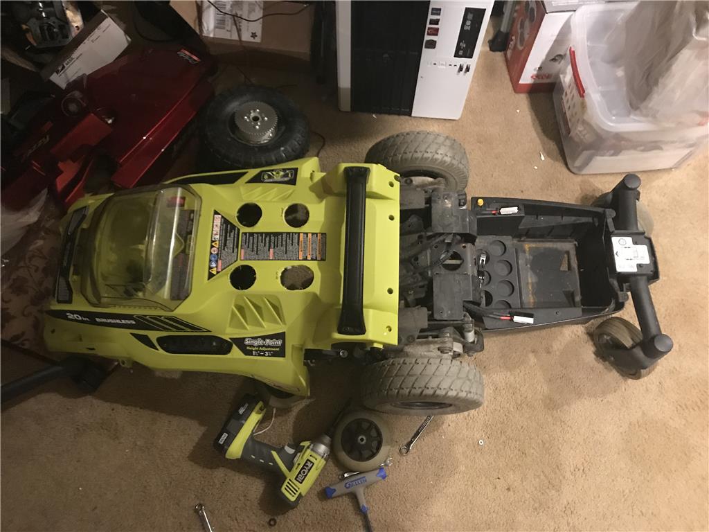
Haha , yes a heavily modified nerf vulcan cannon. I'll take a pic of it tommorow. Anyways I tore down the mower to inspect the frame , wiring and general room for equipment. I mocked up the 10 inch harbor freight wheels and tires on the mower. If this thing was blacked out it would look like the batmobile! Not even kidding.
A NINJA MOWER ..... Killer of Dandy Lions. Silent but Deadly !
Just think if it had 4WD it would make a killer monster truck.
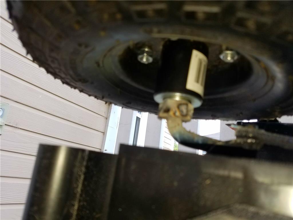
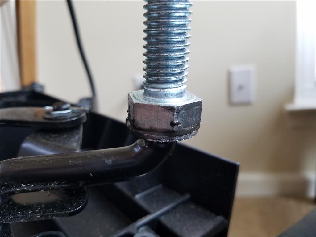
Ok so I'm fitting the mower with 5/8" wide by 3 inches long zinc coated bolts as rear wheel axles. I used a saw to cut the original 1/2 " axle down to the flat spot that the original bearing was pressed against.
Here is the first zinc steel bolt being fitted onto the bung where the original 1/2" axle was tack welded on. It has a 3 inch shafts. I used JB weld Knicks for the flat surface to flat surface weld and next I will sand the edges that squished out and apply another 1/8" layer all the way around of high strength jb weld. Once it sets I will sand that and apply a third and final layer. The goal is to basically use a whole tube on each axle to handle about 30 pounds of weight on each wheel.
To prep both the bolt head and the axle face I sanded off all powder coat with 60 grit sand paper. I will update on the next layers and test fit tonight.
The next prepped face
Ok so I discovered that the JB epoxy weld cannot live up to this job , so I will move on to welding tommorow. I think the axle and the bung are both some kind of steel so I should be able to use my 90 amp might Welder on them. Sadly it's been many years since I have welded anything so I will practice of a scrap piece so I do not totally bugger it up.
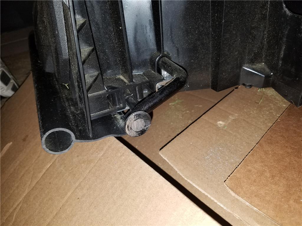
First axle tacked on in 2 or 3 places. It feels solid enough. I will wait till later once the motor is mounted to make a bead. I need to make sure everything lines up well.
Ok second axle tacked on. Here are pics with wheels on and different height settings.
Man, That's a cool machine. cool Can't wait to see it eating some grass!
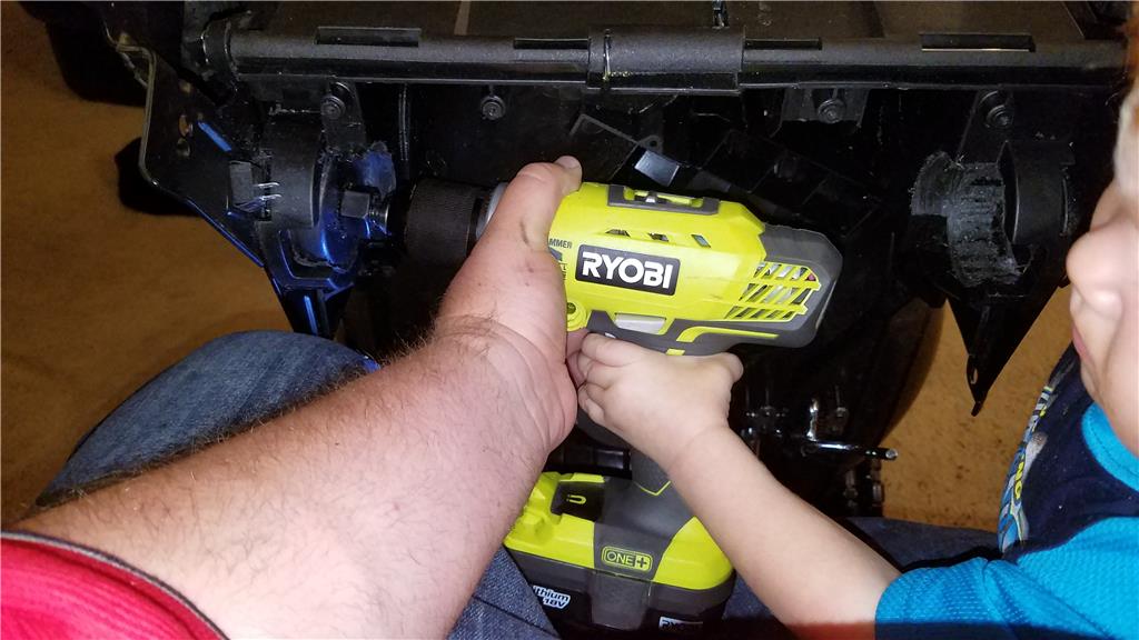
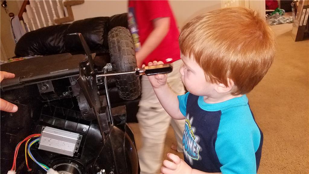
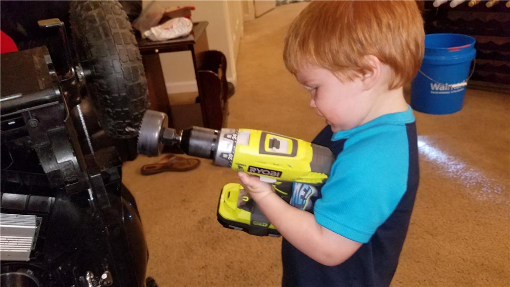
My girlfriends kids look over building , they are so interested! Especially the 2 yr old
Yes he totally drilled a hole! , with me starting it and holding the drill ofcourse as he pulled the trigger ;)
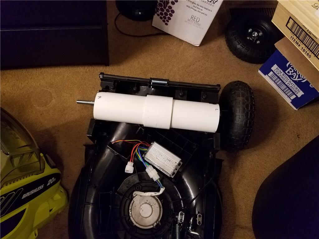
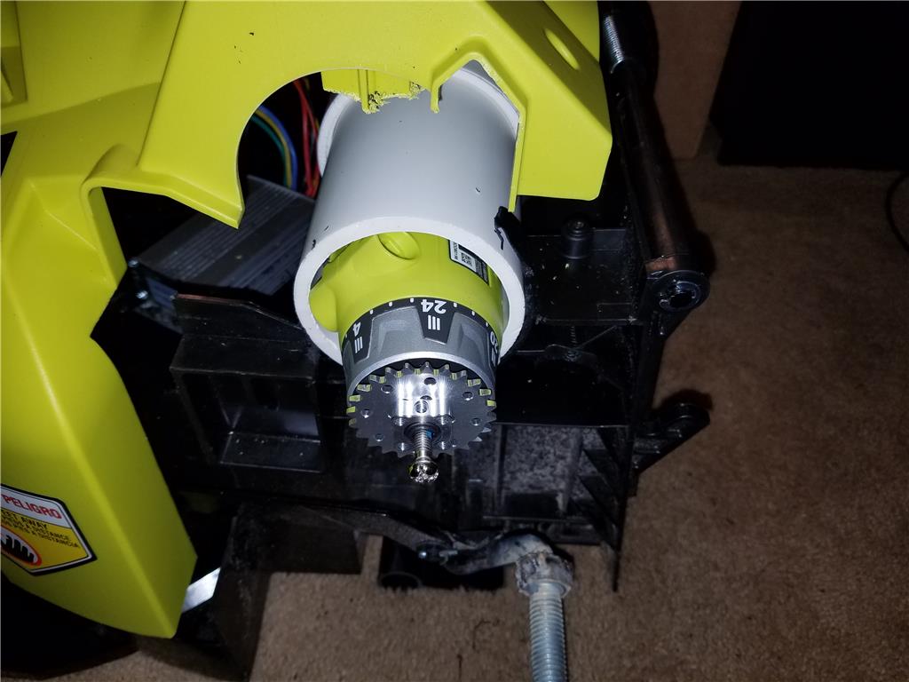
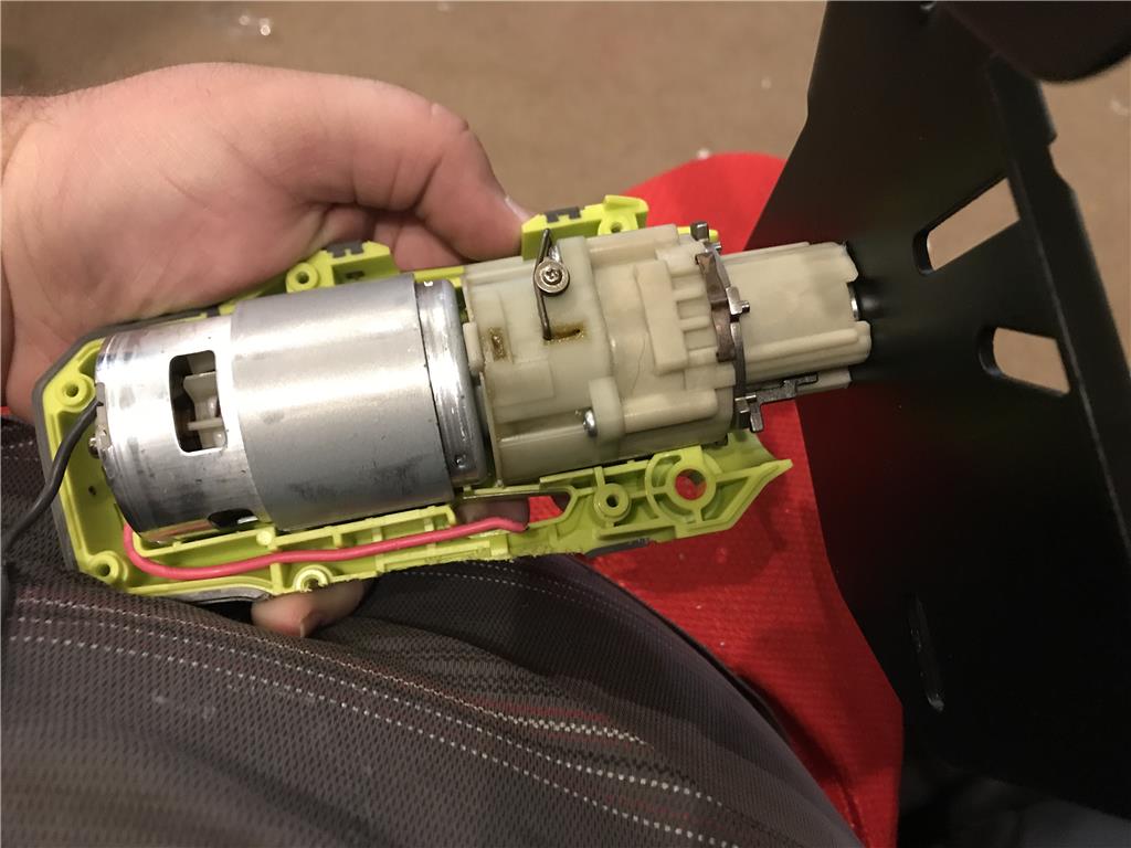
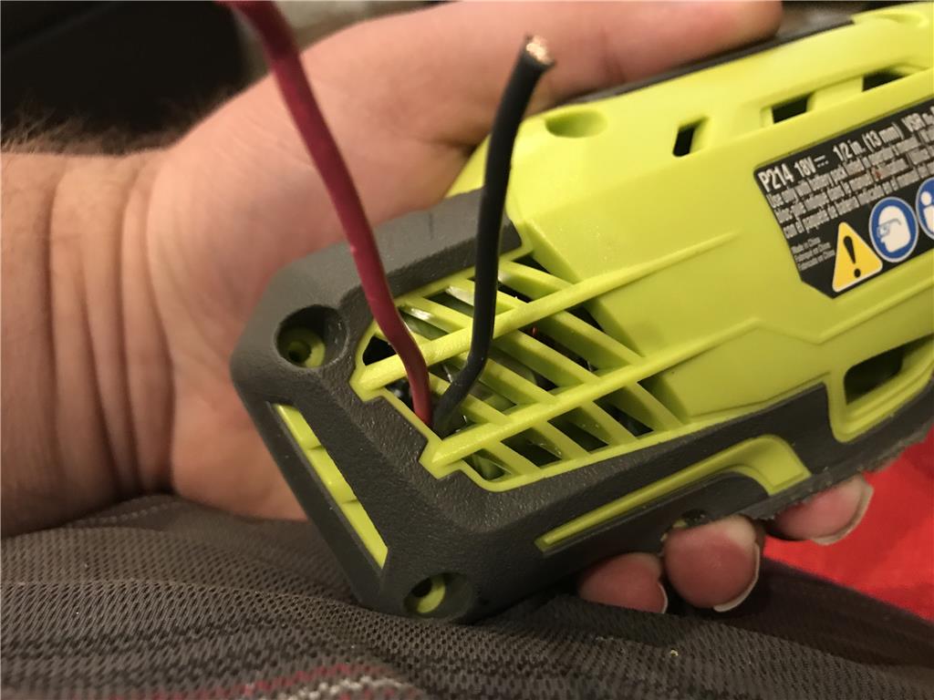
I decided the first half of the motor mounts could be bored through the frame , then run a large bolt through the drills motor casing that was originally intended to be the mount for the second handle grip. I believe I will improvise with pvc pipe to make a sort of cradle for the other half. I can use instamorph to make a glove molded fit to the motor and cut a couple slots to feed soothing like a hose clamp through that can be tightened down.
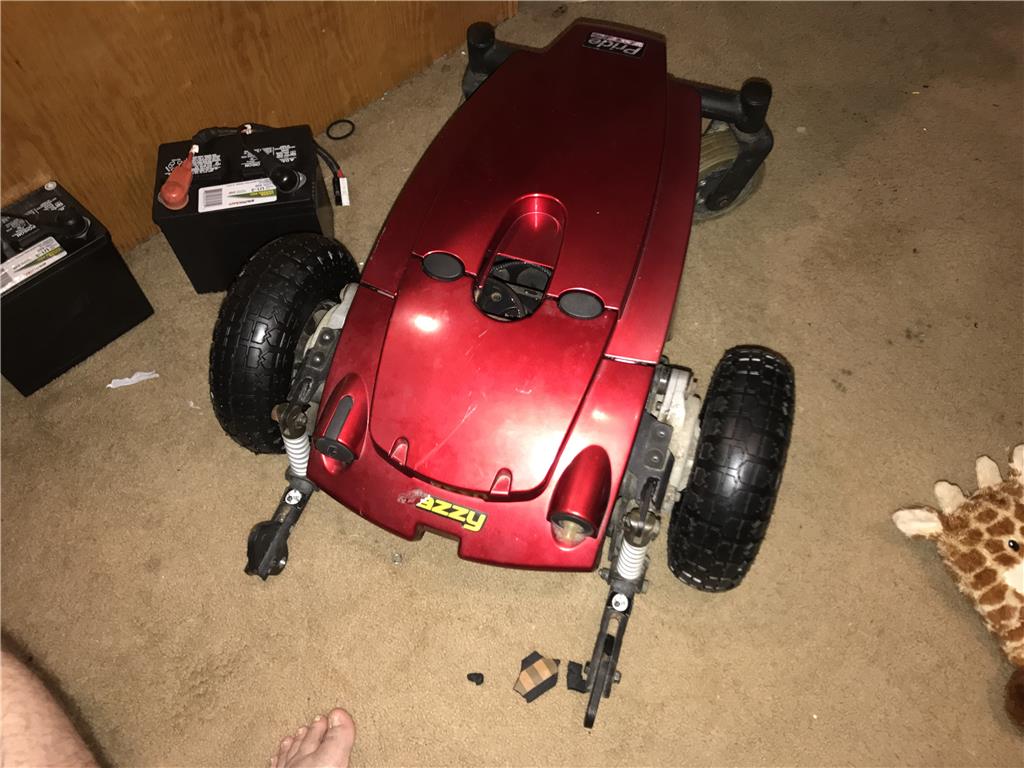
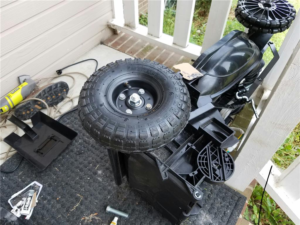
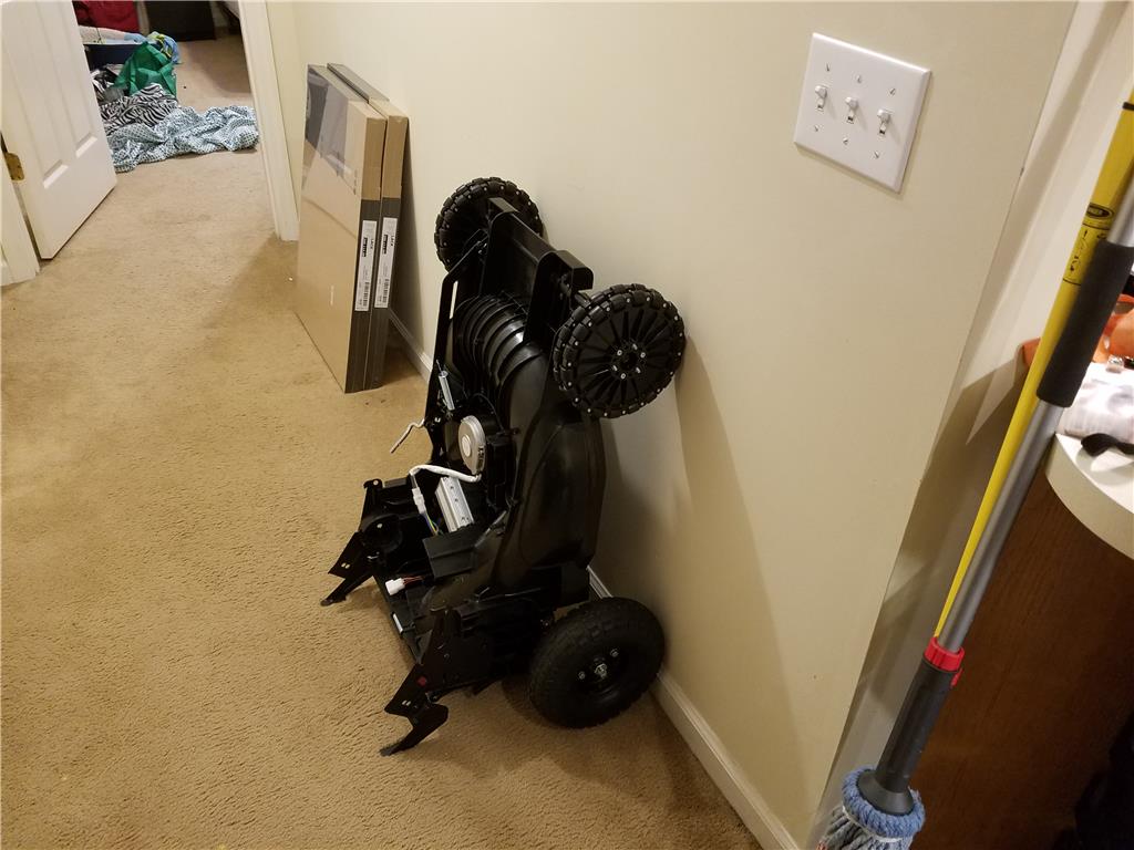
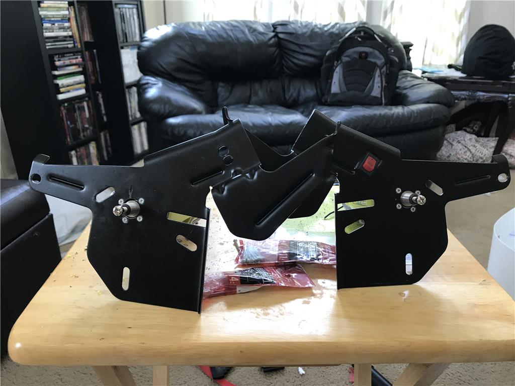
I believe I have decided on keeping the original handle mounts for the mower since they are all steel and have feet that make storing this project easier by standing it up on end like so...
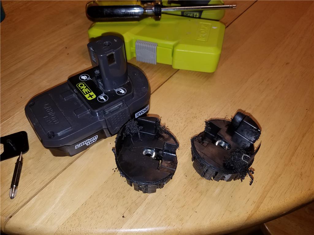
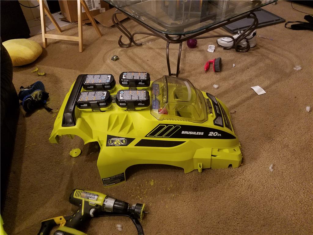
I am honestly still trying to figure out where I will mount the 1 or 2 18 volt drill battery connectors. There simply is not enough room in the battery area unless I compromise on having one 40 volt 5 amp hr battery instead of two , and also compromising on having only one 18 volt battery as well which the largest I can buy is 4AH.
Here are the two cut outs I just removed and a example battery pack. These are only 1.5 AH 18v , the 4AH is more than twice as thick, but the same footprint.
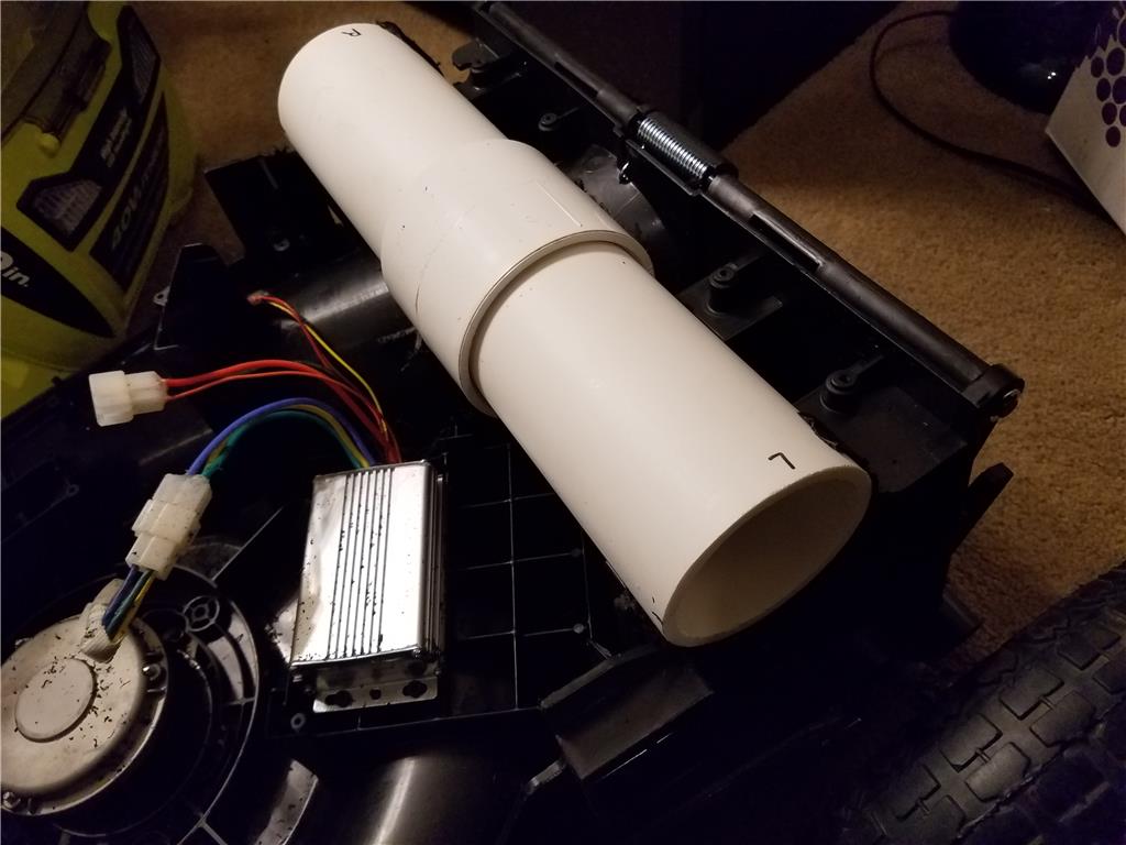
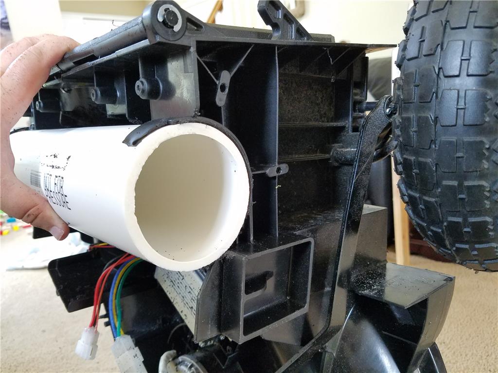
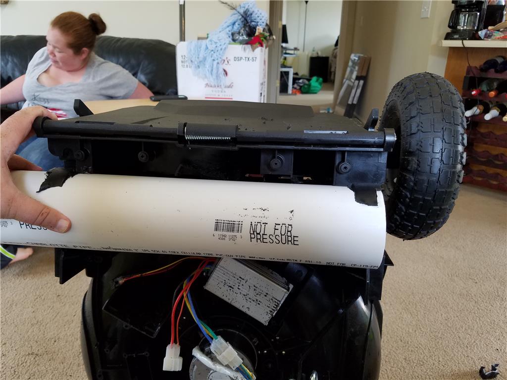
Ok so I started using pvc as a base for mounting the drill motors. I must use the casing because it holds the transmission and motor together. First I carefully cut out a 3 inch hole through the frame from one side to the other. Then I trimmed the grass outlet chute to clear the pvc pipe straight across. This way I really only need to mount each end of the tube.
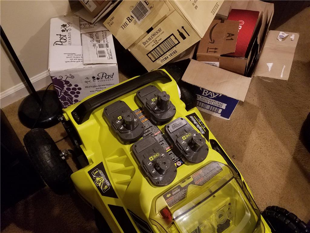
Ok , I am taking a liking to the inline arrangement of the drill lithium ion batteries. , what do you guys think?
Right now the drill mounts are just sitting in the holes in drilled out for them , next I will likely use some instamorph to make them fit tighter and then screw them in.
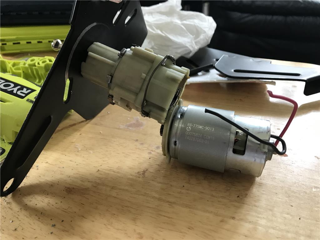
These are the motors and gearboxes I pulled out of the drills while harvesting them.
Pickup up another extended capacity battery to be the second battery that will be wired in parallel with the first for double run time. 40 volts at 4.2 ah. I do have the option to double this at any time with 40v 5ah extended run time batteries which would give a total 10 ah of runtime. This is believe will be what I move to so that the robot can make it through the entire yard without stopping.
I picked up this battery for free from Home Depot today by taking one of the problematic reconditioned batteries back in.
Great work, can't wait to see this in action!
Just thought I'll mention, in your postings you keep referring to the Batteries as 'Lipo batteries' and I believe there lithium-ion batteries. Lipo ( Lithium-polymer ) are a completely different beast to lithium-ion. Lipo's should never be put in parallel as they need to be balanced.
Chris.
Clever and good looking. I'm enjoying your work. Don't stop posting. ;)
Thank you for your order!
Below is a copy of the information you have submitted. You will also receive a copy of this information via e-mail. When your order ships, you will receive a separate shipment notification.
Your invoice number is -----------
Qty Description Unit Amount
2 (545560) 1/2 inch Bore Set Screw Hub $4.99 $9.98 (0.770 inch) * Weight: 0.02 lbs. each
2 (615126) 48T Aluminum Hub Sprocket $7.19 $14.38 (0.250 in) * Weight: 0.11 lbs. each
2 (615106) 24T Aluminum Hub Sprocket $4.79 $9.58 (0.250 in) * Weight: 0.04 lbs. each
6 (C250) .250 inch Metal Chain (12 inch) $8.99 $53.94 and 1 connecting link * Weight: 0.09 lbs. each
1 (CHB475) .250 inch Chain Breaker $12.95 $12.95 * Weight: 0.12 lbs. each
6 (6261K108) .250inch Connecting Link $2.95 $17.70 * Weight: 0.01 lbs. each
8 (91251A151) 6-32x3/4 inch Socket Head $0.35 $2.80 Machine Cap Screw * Weight: 0.01 lbs. each
8 (91251A153) 6-32x1 inch Socket Head $0.35 $2.80 Machine Cap Screw * Weight: 0.01 lbs. each
Order placed at: Fri Jul 15 12:51:17 2016
Ship/Deliver To: Josh Starnes
OK so here is my ServoCIty order, Originally I ordered plastic chain and sprockets but I am concerned I will probably break them with the torque of these drill motors which ryobi claims is around 600 oz in of torque and max 400 rpm on low drive mode. So metal chain is probably the way to go to longevity reasons. Hopefully I will get my order by Tues so I can start installing it since that's my next off day.
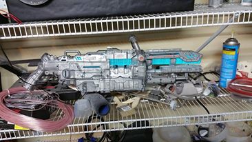
Just to throw this out there , this is the dragon con costume. I am thinking I will control all the lighting and vapor effects with a Web and phone on the chest.
LOL! "Luke, I am your father"! :P
Looks cool but..... Your a more dedicated fan then I would be. I couldn't keep that rig on my face while I'm walking around a convention.
That gun is sick! (sick in a good way). ;)
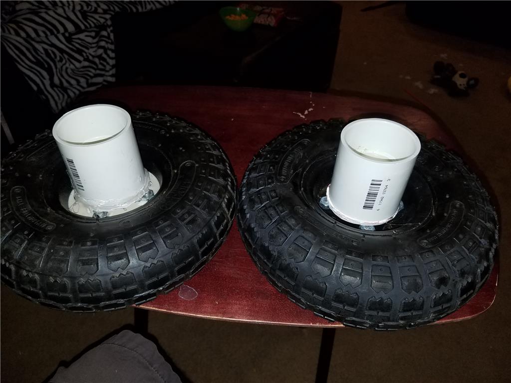
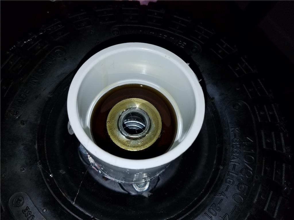
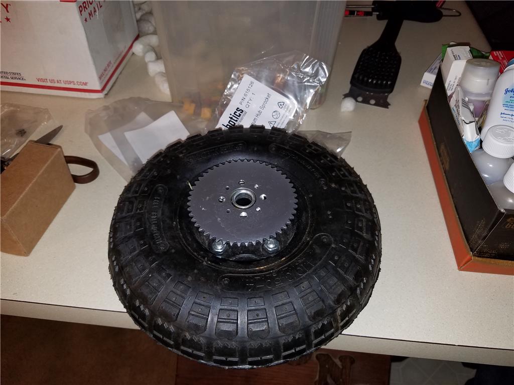
Ok so I am trying to get clever with mounting the aluminum sprockets to the wheels. I need a surface wide enough to accommodate the pre drilled mounting holes. I need at least 4 but I will probably use all eight to relieve general stress.
I purchased 2.5 inch pvc couplers and hit glued them into place with a foam board backer to hold the liquid plastic in while it cures.
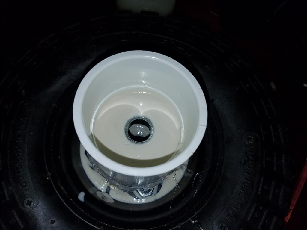
Liquid in place...
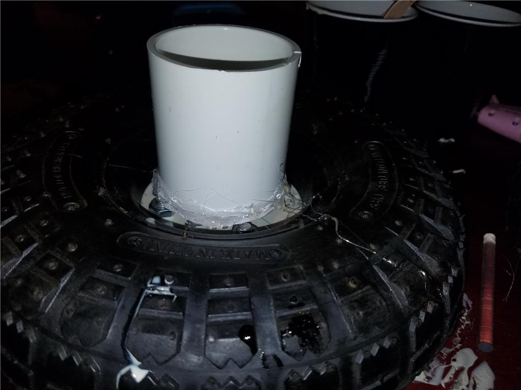
Polyurethane resin cured , 80 shore
Both are curing overnight and then I can cut the pvc couplers down to the level of the plastic surface I just made.
Looking good Josh! I wish I had time to work on bots. Can't wait to see this in action.
Where do you get your liquid plastic?
This plastic I picked up from hobby lobby. It was alumilite plastic resin. It's tough stuff not not brittle. Reminds me of abs. Also no funny smell when it cures! They have a fast cure version , 5 min but It gets very hot when curing.
Hello all, this thread was on life support , but I am bringing it back.... CLEAR! Booosh zzzt!
So I have been distracted with home improvements and car projects. I just finished the custom wheels for the Rav4 I bought a month ago.... I am a big fan of red.
So a big incentive is the 2017 Ryobi nation contests, they have monthly and yearly as well. Up to 2500 for first place, so why not submit a robot that is 95 percent Ryobi products ! Muahaha
Think I could win?
OK so back where we left off I was battling with how to handle the drill motors being mounted and the sprockets. The motor is not affixed to the gearbox so somthing has to hold them together. I was thinking of using the original casing of the drill ( and that is still possible) however I really need these things to breath so they do not get too hot. I am after all going to run them on constantly and probably half or more of their rated load. I imagine they would get toasty without air.
maybe one if these 550 RS motor heat sinks on each motor will do the job? we will see later. I might order a couple and see if they fit.
I believe I will just expose the whole motor as it will give me more direct mounting to the PVC pipe and more air. The motor has vents but they will not do much good unless they can breath.
OK so for mounting I will use a combination of instamorph and and worm gear radiator hose clamps. The instamorph I can use to make an impression to tightly fit the bottom of the motors and ALSO help keep the gearbox and motor closely meshed.
If needed I could swap the poly morph for epoxy putty if heat softens the plastic instamorph. I just need to test that it can securely hold the motor and gearbox close together.
@jstarne1, glad to see you're back at your project been waiting to see your final product.
I am pretty sure the instamorph will soften or melt when in use. (the reusable on the label is the big hint). I know of some builders who have had their stuff start to melt on a hot day in a window, so next to a spinning motor on a hot day when you are mowing the grass would be a bad time for it to start to fail.
Alan
Hey thanks man! It would be nice to have now that grass is growing practically an inch a day.
So I think I have most everything to get the ball rolling minus some misc like certain screws and such.
To DO
Cut out the pvc pipe to get the motors in
Use the instamorph to connect gearbox and motor then strap down with 2-3 inch hose clamps. 2-4 on each motor/ gearbox
Solder up the xt60 connectors to all the battery connectors and motors
Mount up sprockets to the wheel hubs and the shaft on the motors and make a custom chain to fit them.
I will need misc stuff like screws for example and more solder but this is a start.
@thetechguru , you are probably right, but I don't want my first try to not allow any for adjustments. I am considering epoxy putty for that so I can put it just where I need it.
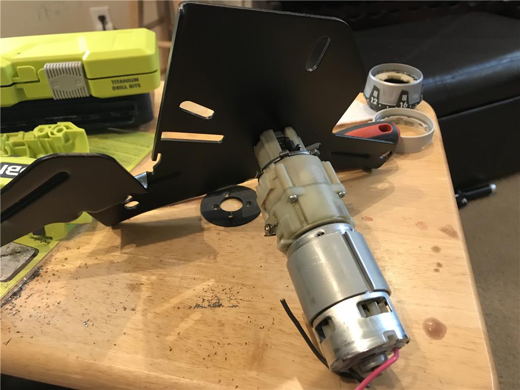
I went back and looked and I still have the steel end plate mounts so I can maybe drill 4 additional holes to mount the edge of the gearbox.
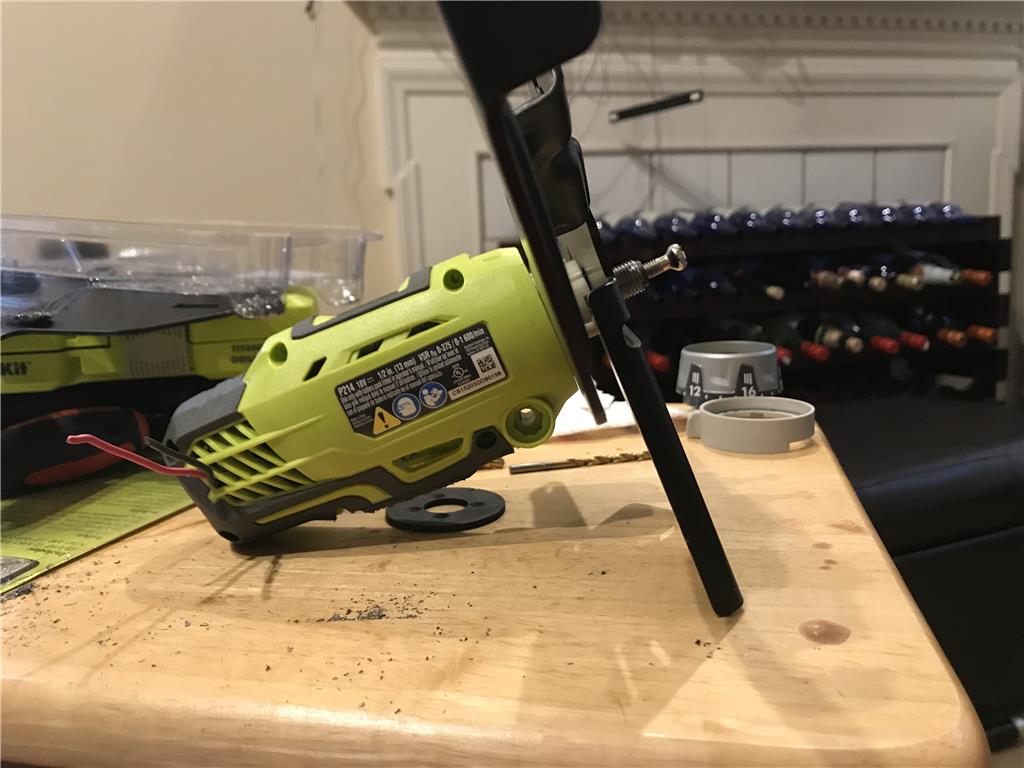
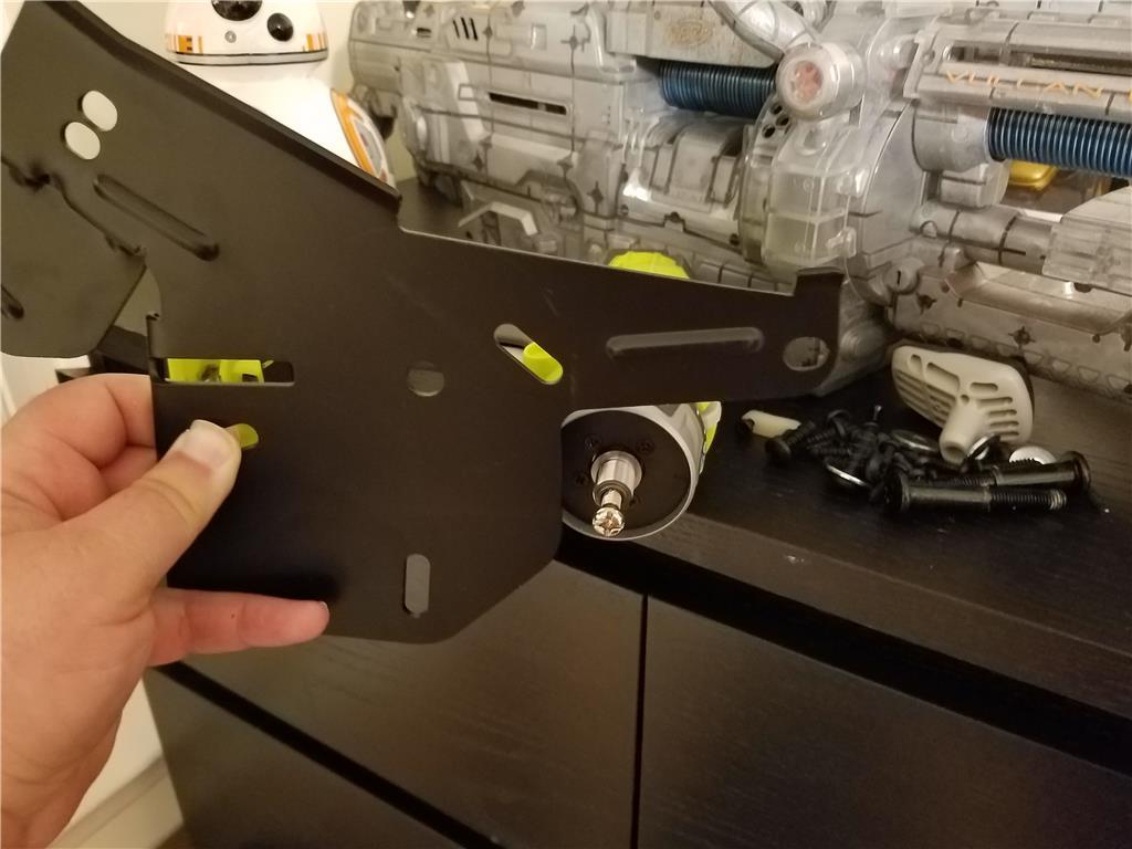
Here is that steel plate that also acts as a stand I was referring to.
Only two of the mounting points that connect to the frame of the mower, but I think that can work. I need to pickup some diamond tip bits and longer screws to drill the 4 additional holes to mount up the gearbox.
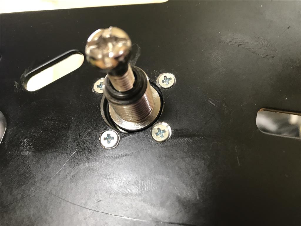
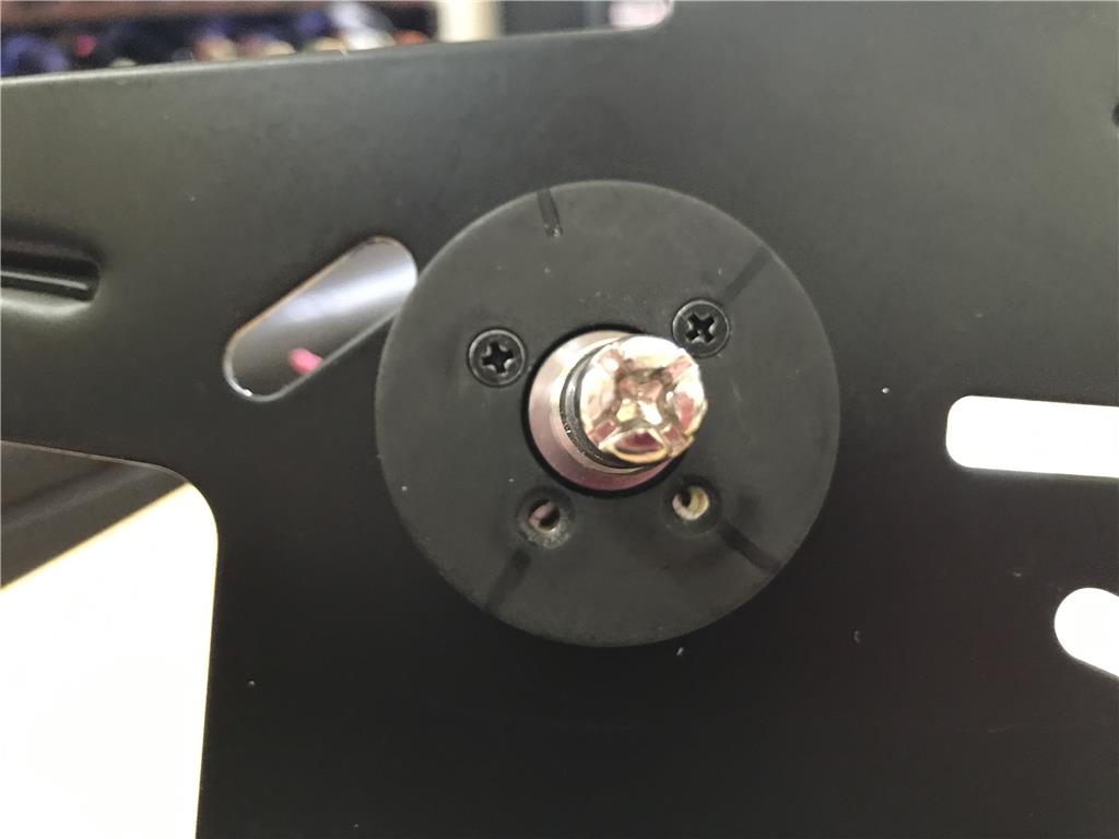
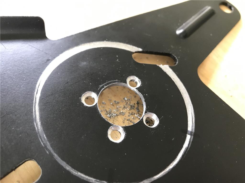
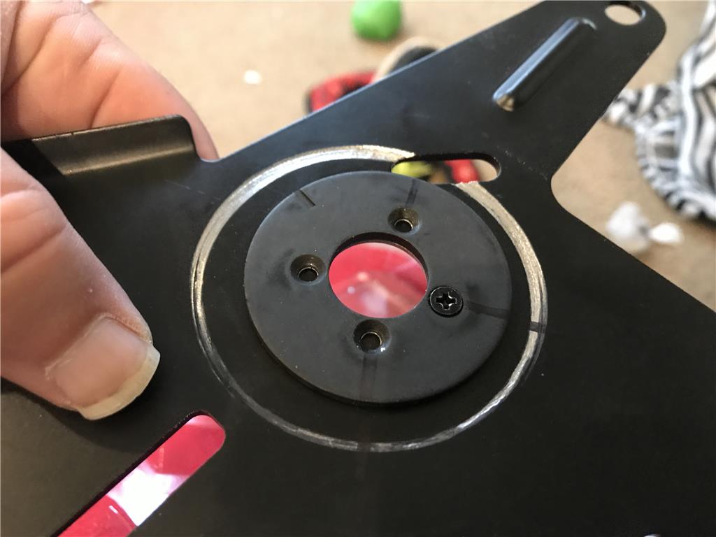
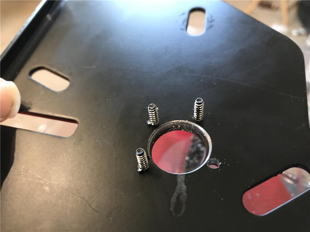
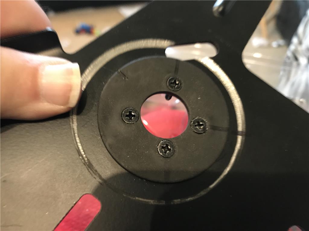
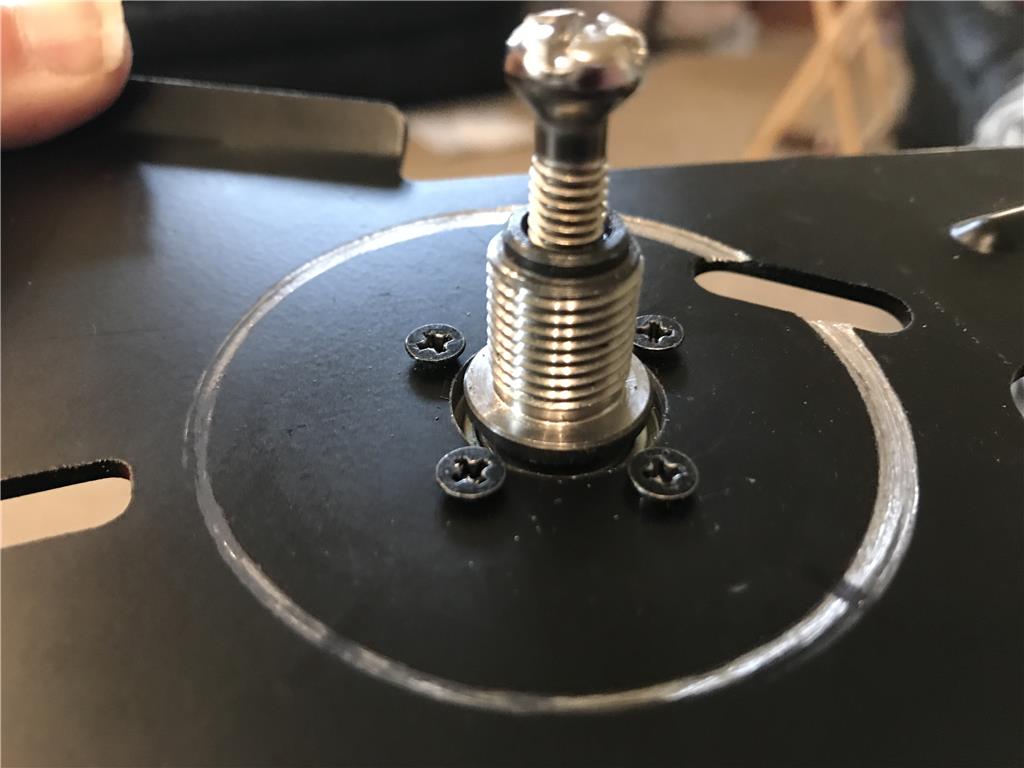
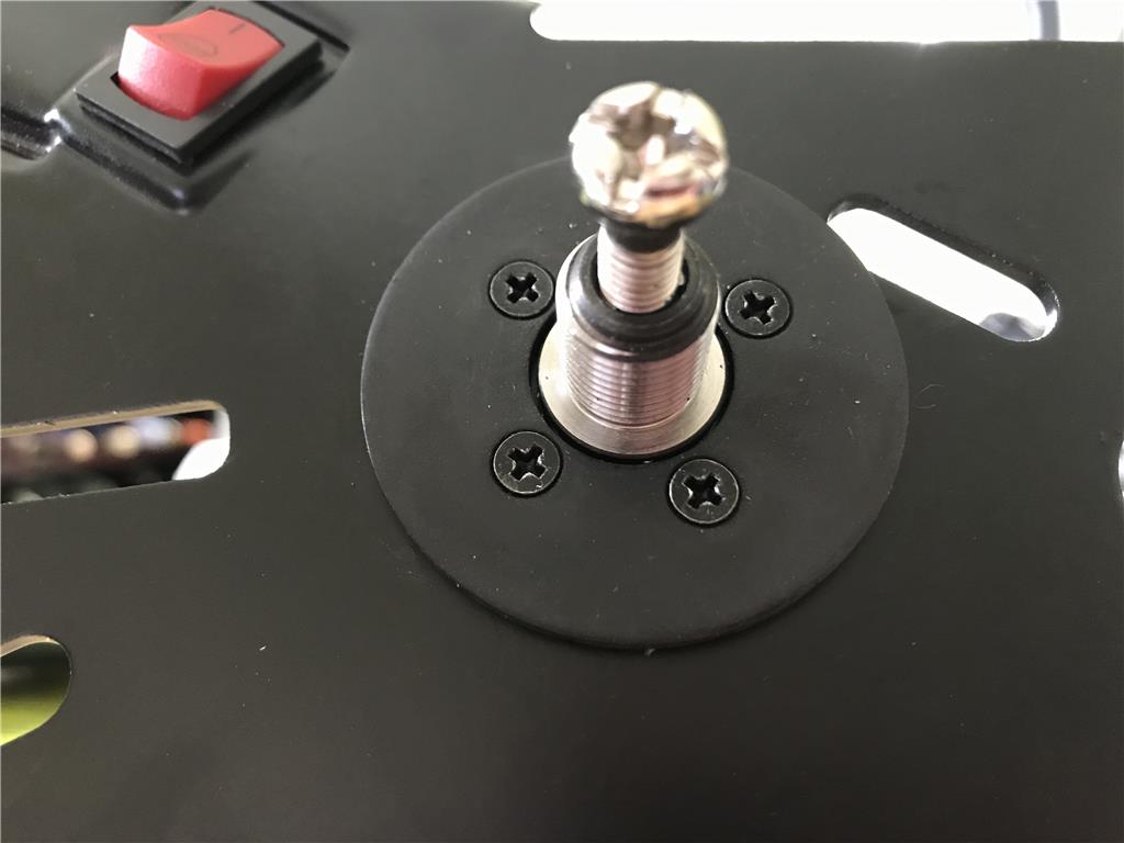
Ok so I picked up titanium coated bits so I can drill through this 1/8th inch steel. Just so happens the outside plate of the gearbox is also 1/8 inch steel. I thought to myself that I could likely use the same screws to mount the play to the gearbox. I used the largest bit I had and I still need to widen the hole more for the bearing at the base of the shaft.
Shaft through the hole . I need to widen it out another quarter inch I think and I will try getting longer screws tomorrow.
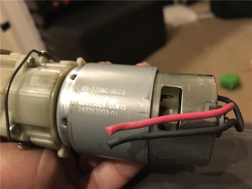
Found the motor markings , RS775WC-9013
6-18 volts , so it says it is 153 amps drawn at stall and 20 amps nominal torque
This little motor is a beast!
Just take one of your Laser guns and trim it out !
I never realized those motors were so mean. What controller were you going to use?
I don't have a laser but boy do I want one ! It's on the project list!
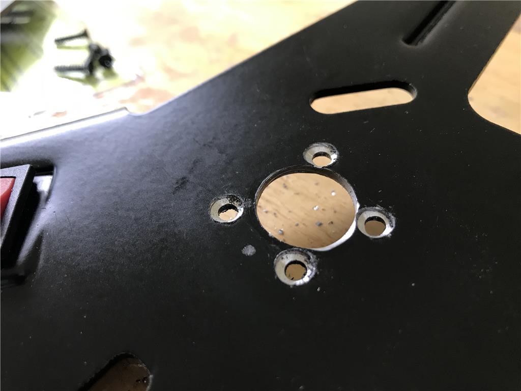
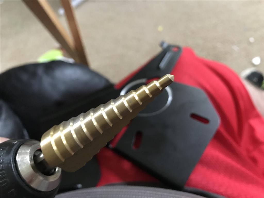
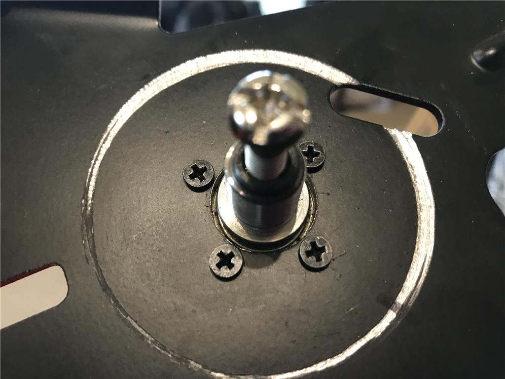
Anyways I ran to harbor freight to get a titanium stepper but to carefully widen the area around the shaft to clear for the main bearing. The mounting holes were spot on except the last one was about one mm off , so I screwed down the plate and drilled out the last one as a correction.
I have a sabertooth 2 x 12 but I think I may play it safe and go with a different configuration. I have two h bridges off Ebay I picked up. I was thinking of running both L and R on the h bridge paralleled to one motor which should share the load and run cooler. When I saw the nominal 20 amp at max torque I was worried I might over heat the sabertooth. I will try the 2 x12 sabertooth first if I can find it in my electronics bins.
Just for today I am working to get motors mounted and connectors soldered onto the motors and I can go from there.
Ok round 2 , I need to do the other side and I will takes pics step by step in case anyone ever needs to surface mount a motor.
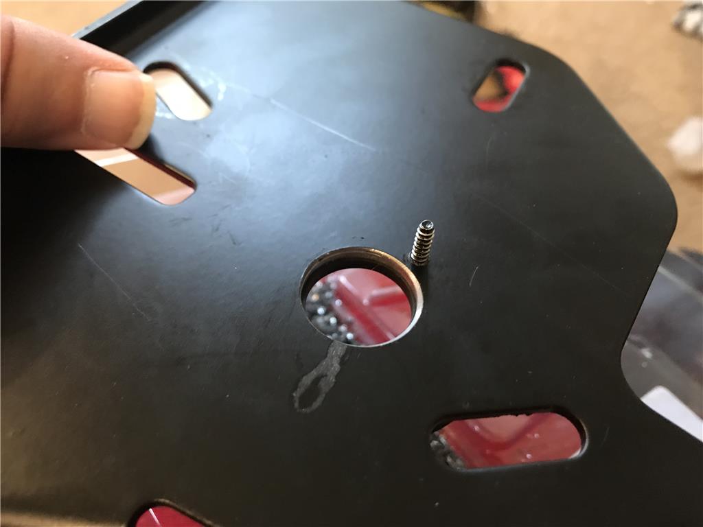
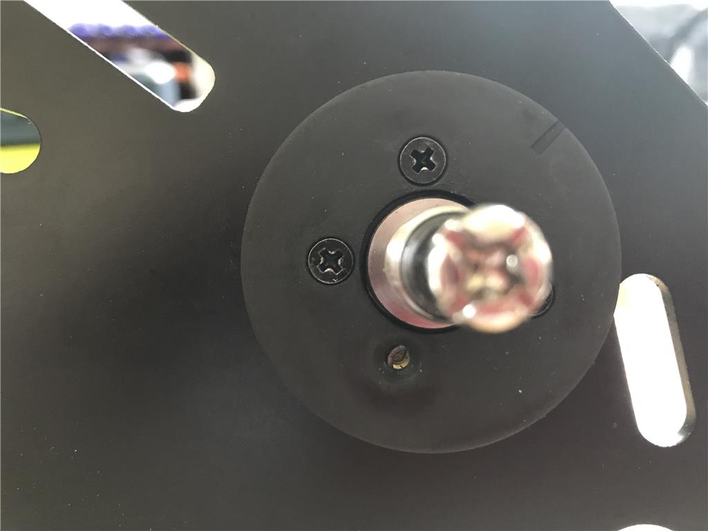
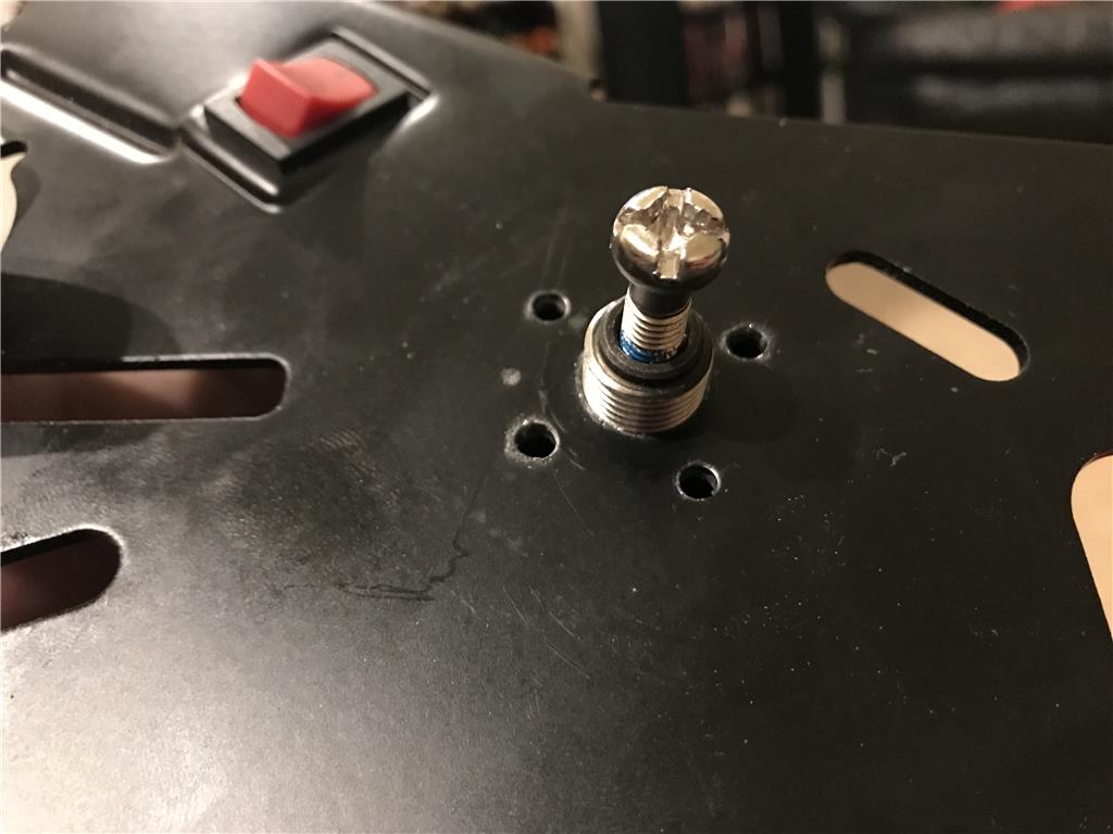
The screws are aligned with the gearbox holes but these screws require a counter sink to screw all the way in. I will use the tip of the stepper /uni-bit to make a counter sink.
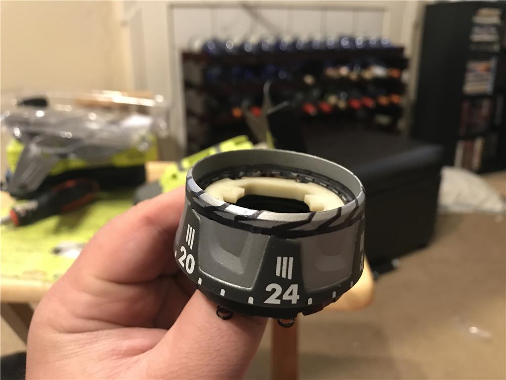
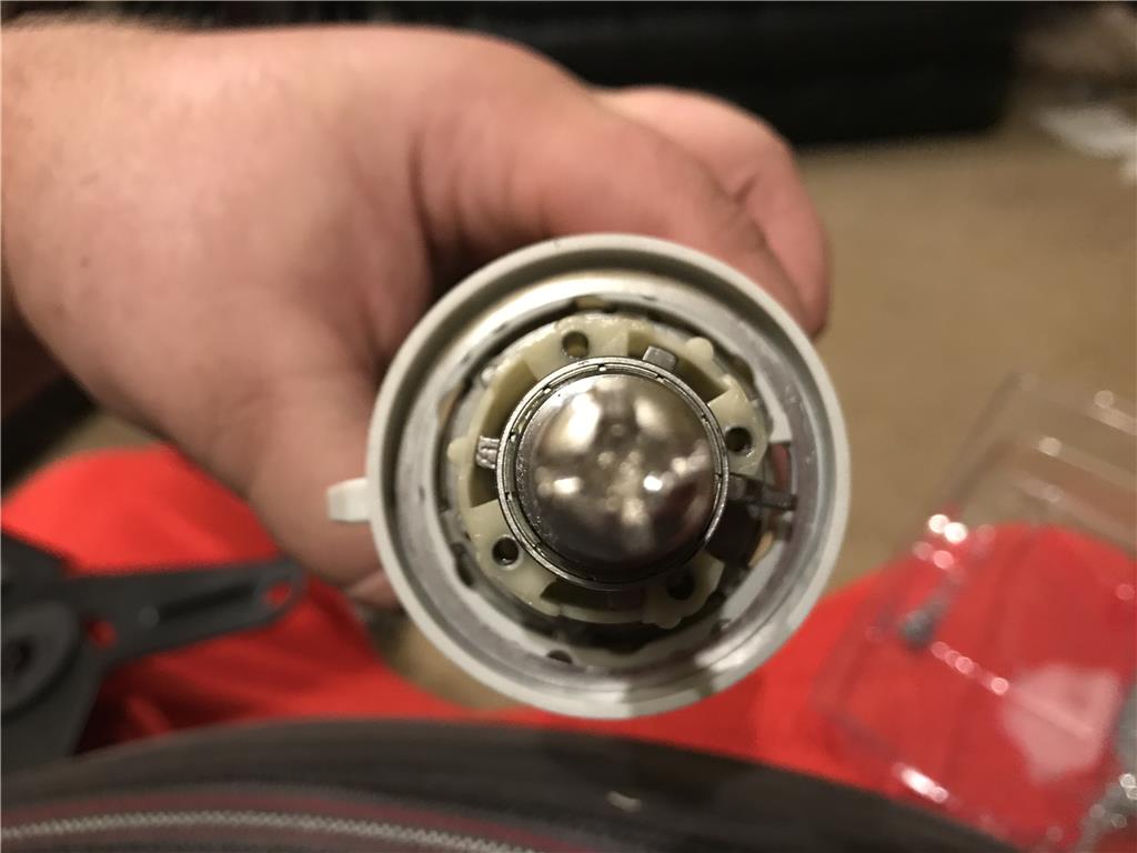
The motor unhooks from the gearbox with a simple 1/8 twist. I believe I will use a portion of the original casing to keep them mated together.
I will add a large hole at the end for the power wires to feed through
After measuring I found that there is too much plastic lip on the clutch sleeve. I will need to find the dremel and trim down the clutch so that I can fit it behind the metal plate and still be able to screw it all the way down to the face of the gearbox.
On a side note I am going to go find those nail clippers! Those are scary.
Those nails will work well for stripping wire.....
Project is going well. Looking forward to more.
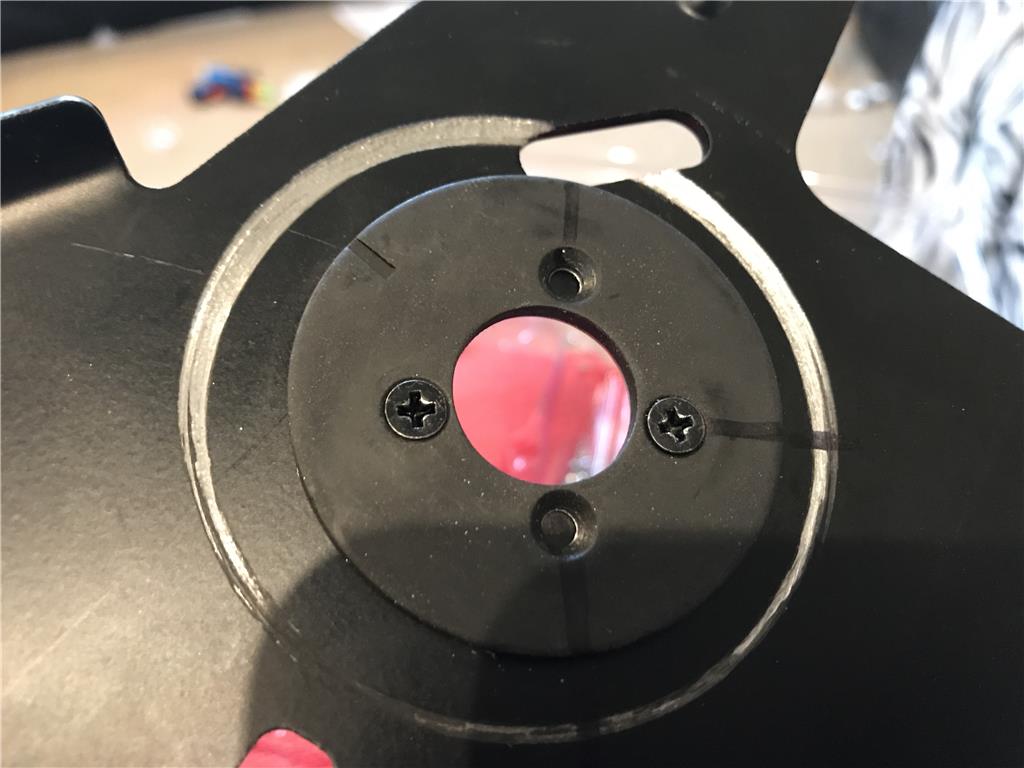
Ok so I used a larger bit and slowly machined out the holes to countersink the screws.
They sink in well now
Ok so you are going to laugh but I drilled the pattern from the WRONG side on the left bracet. At first I thought it would be ok till I found the holes are not symmetrical. So I had to make some adjustments. Ugh
You can see they are a couple mm off, it is fixable but I am still grumpy
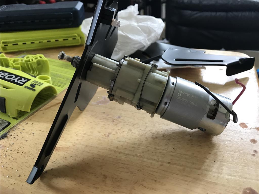
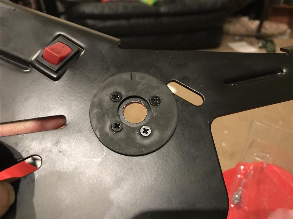
The left motor is mounted to the steel plate. I reassembled the casing to mate the motor to the gearbox. I may drill a couple 1 inch holes to act as additional vents to cool the motor.
I made a hole on the ends of the casing to feed the power wires through.
Josh, I am not laughing, that is easy to do. Looking forward to your updates on your project. Steve S
A quick test for shows I need to do some trimming of the case or the plastic on the frame to line up with the bracket mounting holes. I will do this and go from there.
Oh and thanks Steve , I appreciate the support.
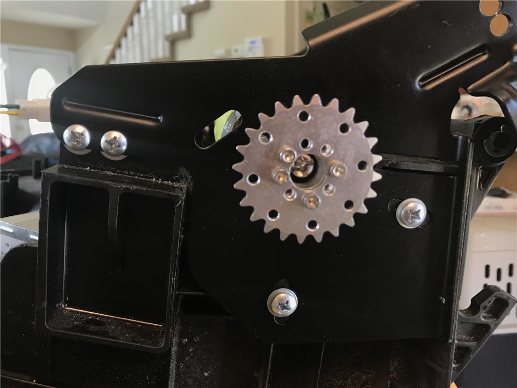
Ok so I dug out the plastic sprockets and chain, I really intended on using the metal chain but the location eludes me. So I will use the plastic chain as a place setter till I find the stronger metal counterpart.
The chain came in a baggy of individual links so I had the pleasure of painstakingly twisting and pushing these links till they snapped together. Poor fingertips :(
I know have 6 feet of this stuff I believe.
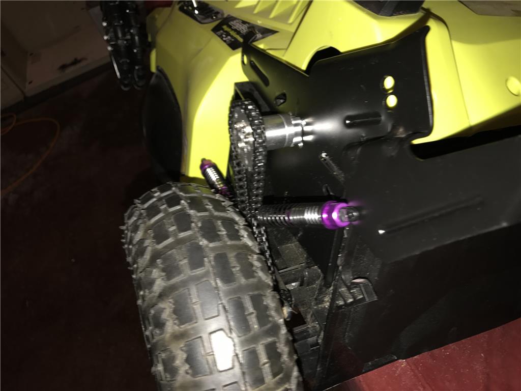
Ok yet another hurdle , once the motors are in I can see the drills output shaft lacks about an inch and a half longer to align with a drive sprocket. Maybe I could weld on an extension?
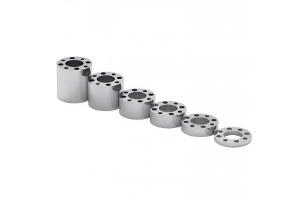
Good news , servo city machines aluminum hub spacers I can use to extend the shaft long enough to align with the wheel hub sprocket.
So now I wait will I get the parts to do this. In the mean time I can start wiring and finding ways to mount the motor controller and the EZ-B as well.
Does anyone know which gets better wifi range , The tiny or the v4 with original wifi shield?
Ok, so I received the spacer kit and I am now waiting to find the aluminum sprockets and metal #25 chain. If I cannot find it before Monday I will place another order.
Until I have metal versions these plastic ones should allow me to start fitting the pieces together. I will need to get matching screws at the hardware store to put it all together.
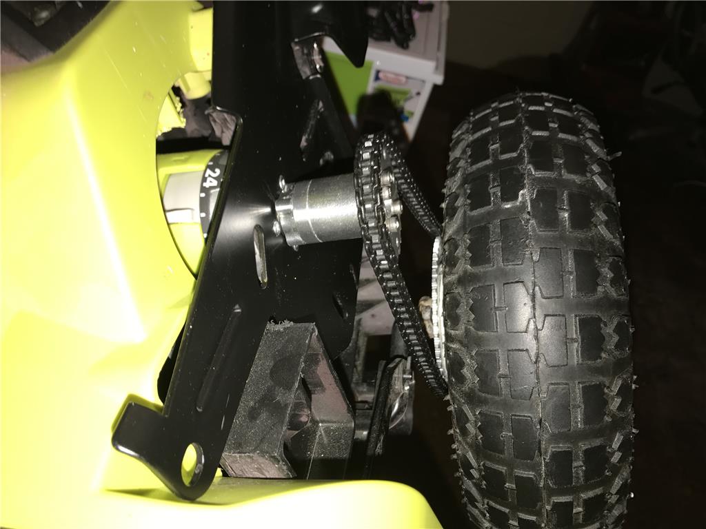
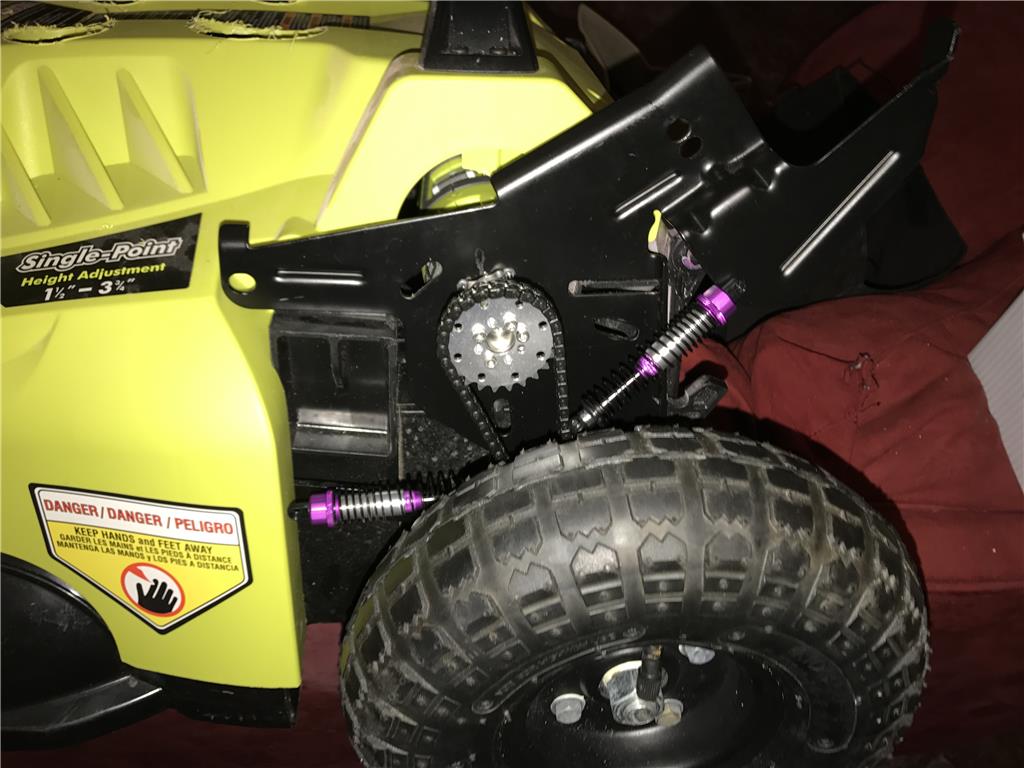
Ok I shortened the chain to test the rolling movement of the sprockets, looks like they are good to go even without an idler
https://www.youtube.com/watch?v=EHsbR9g0kb4
Video showing setup so far and ideas for the next steps.
Looking good and I love the two little shocks absorbers! :)
Chris.
Ha ha, thanks. I have a few sets. Amazing what you can buy direct from china for a few dollars.
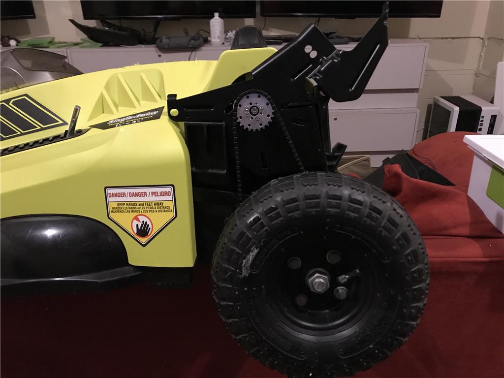
Update:
The plastic on the top of the mower needs to be cut back so I can get it all the way down on top of the motors.
The metal brackets need to be shorten about 1 inch to make the mower top easier to add and remove.
The plastic chain should work for now , but once I can get the mounts fully on the motors I will use the 1 ft links to make a metal .25" chain.
Coming together nicely. Your work is so clean and impressive. I'm looking forward to seeing this run around your yard!
Have you considered that only having one rear wheel drive would possibly cause the mower to angle slightly to one side as it pushes and drives the unit forward? You would have to keep correcting the steering to keep it driving in a stright line. Dual rear drive would keep this from happening (or move the drive to the front). Hope I'm wrong. ;)
Hey Dave , I plan of both right and left motors driving forward at the same time. I imagine without him both it may have issues on uneven grass or mole hills.
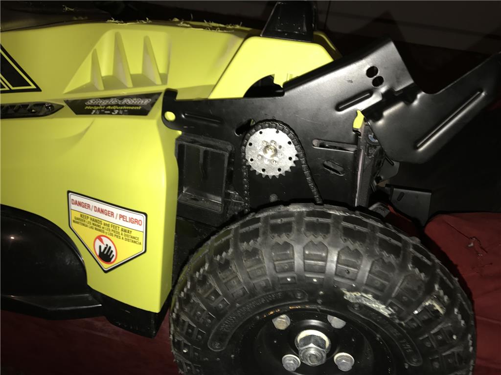
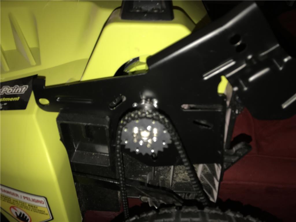
Ok so the smaller screws I picked up never drove down tight so I installed bigger ones and also added two more points of attachment that I could drive down tight on the frame as well. Now there are 4 mounting points for the drive motor and I am satisfied it will hold the drill motors in place. I can easily add two more by filling voids between supports with the liquid plastic and driving directly into those as well, but this looks sturdy.
OK so I have found a fatal flaw in how this is setup, I SHOULD HAVE< done a direct to gearbox wheel mount. The chain drive derails often because variation of the movement of the suspension. It is not the first time I made a big "OOPS". In this case I am going to connect the drive of a small jazzy wheelchair and test it out and it this is smooth I may permanently meld them together.
eek stress Condolences. I feel your pain.
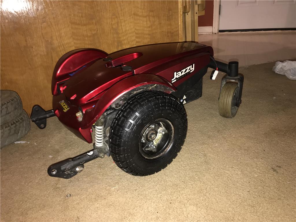
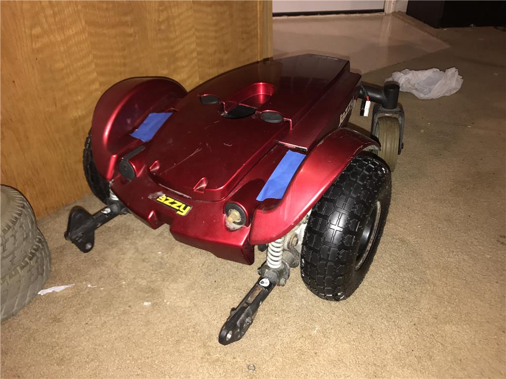
Thankyou for your sympathy ! I was really sad when the tests didn't work out. Such as any experimental project we find kinks. I am going to see if I can just mount the jazzy motors directly into the mower, but first i will test it out with the mower connected to the front of the jazzy
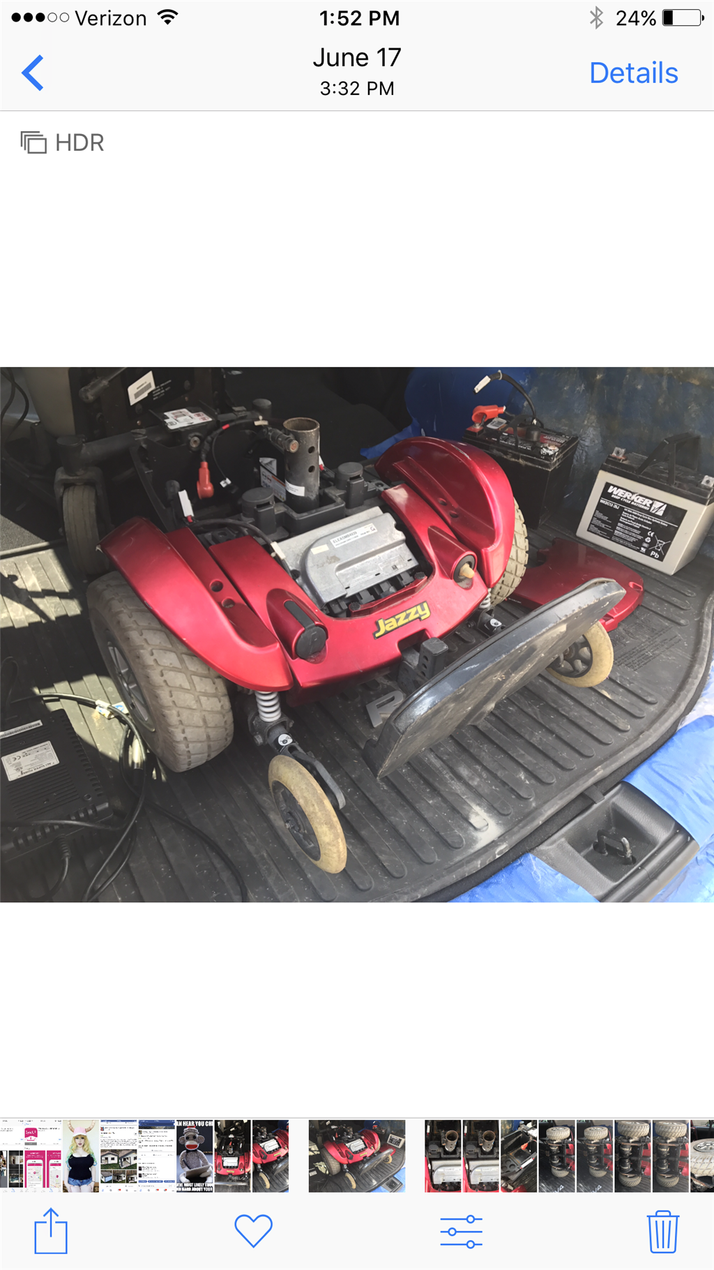
Not pictured but I already picked up 2 U1-3 lawn and garden batteries that pit inside. I may upgrade later to AGM lead acid but not until I see if I really need them for the project.
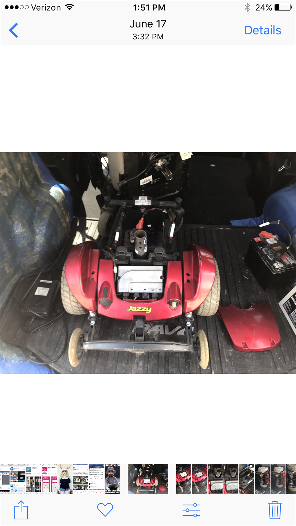
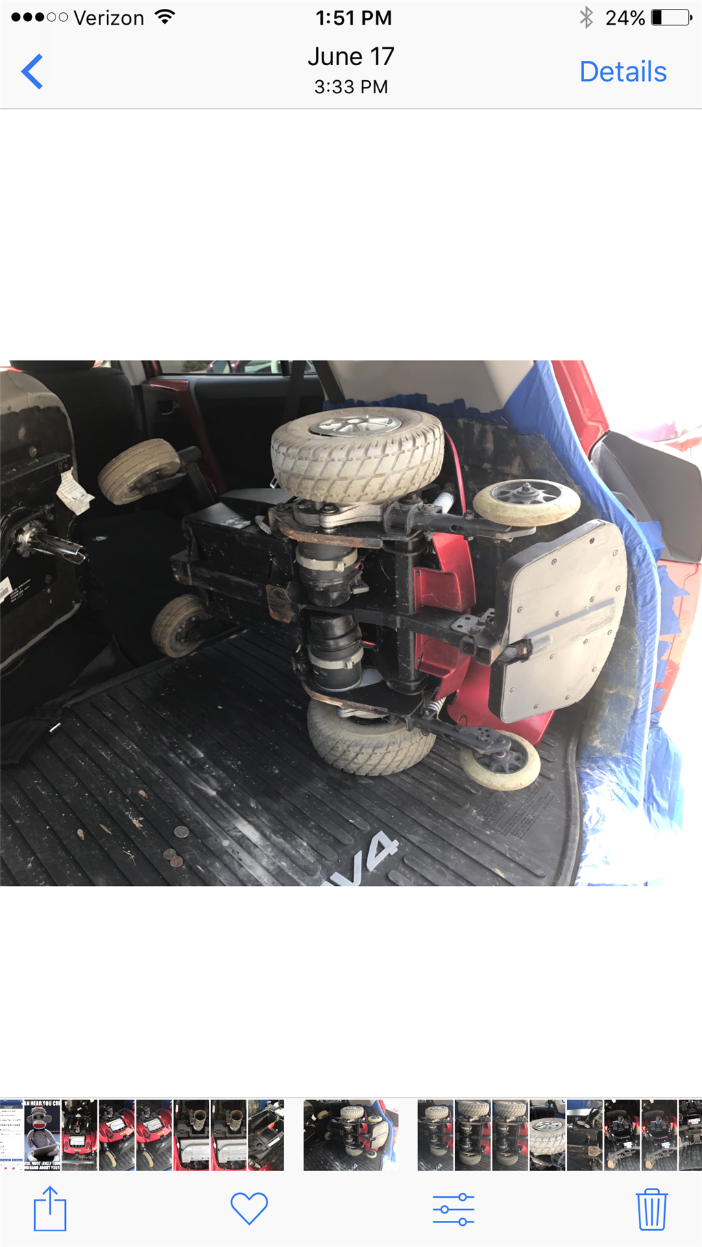
I got this Jazzy Select chair for 110 dollars working at the time but bad batteries.
Ok there might be one or two fixes for the chain issue. First is that I need to remove this adjustable axle because it flexes too much and put in a solid or tube axle that will be in a fixed position. The wheels will need to be able to slide over it, I may try using the same chain and go from there.
As a temporary measure though I could attach it to the jazzy and run it around. I am just so anxious to get something moving! So close
If I do this I am also considering upgrading to number 40 chain which is overkill as far as strength but is much more stable in this short distance that the small chain.
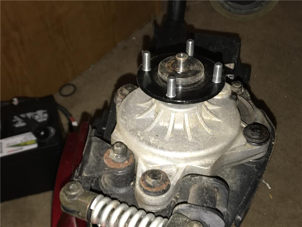
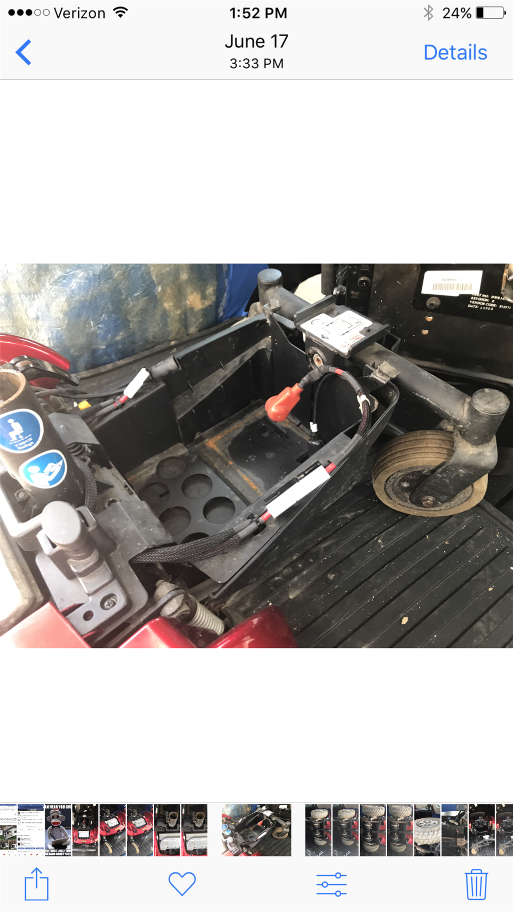
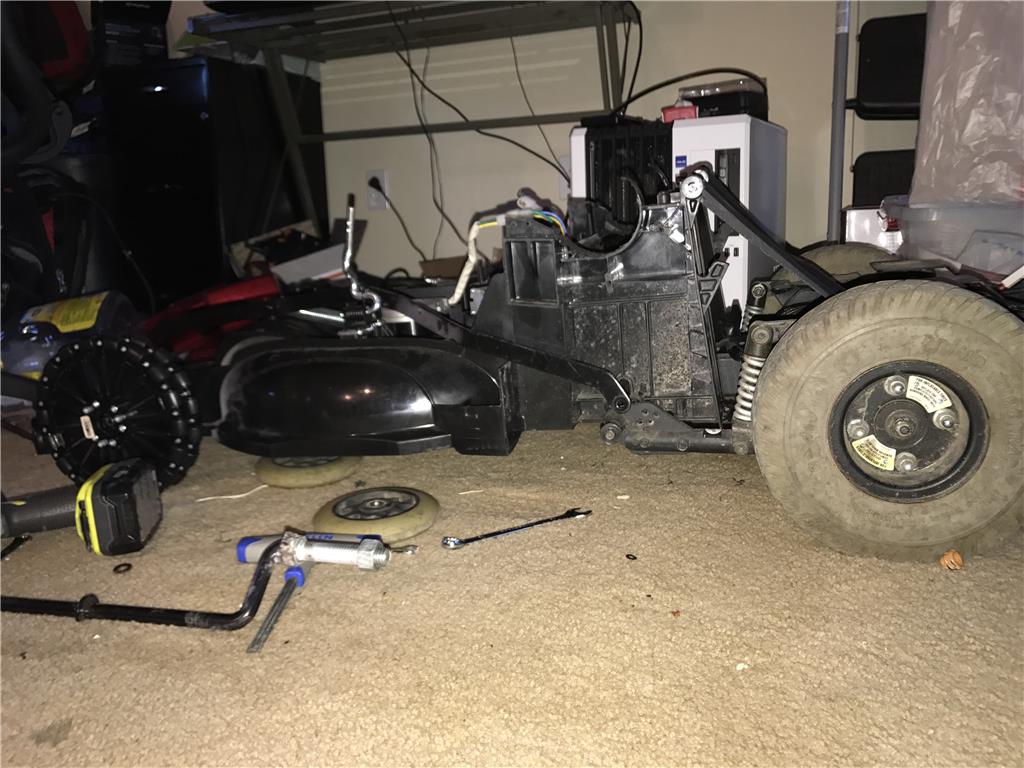
I started stripping down the jazzy and removing brackets , wires and controller that will not be used, it has a circuit breaker set for 30 amps , hmm I wonder if I will leave it in, 15 amps max per battery is not a very high ceiling.
Anyways as always feedback is welcome
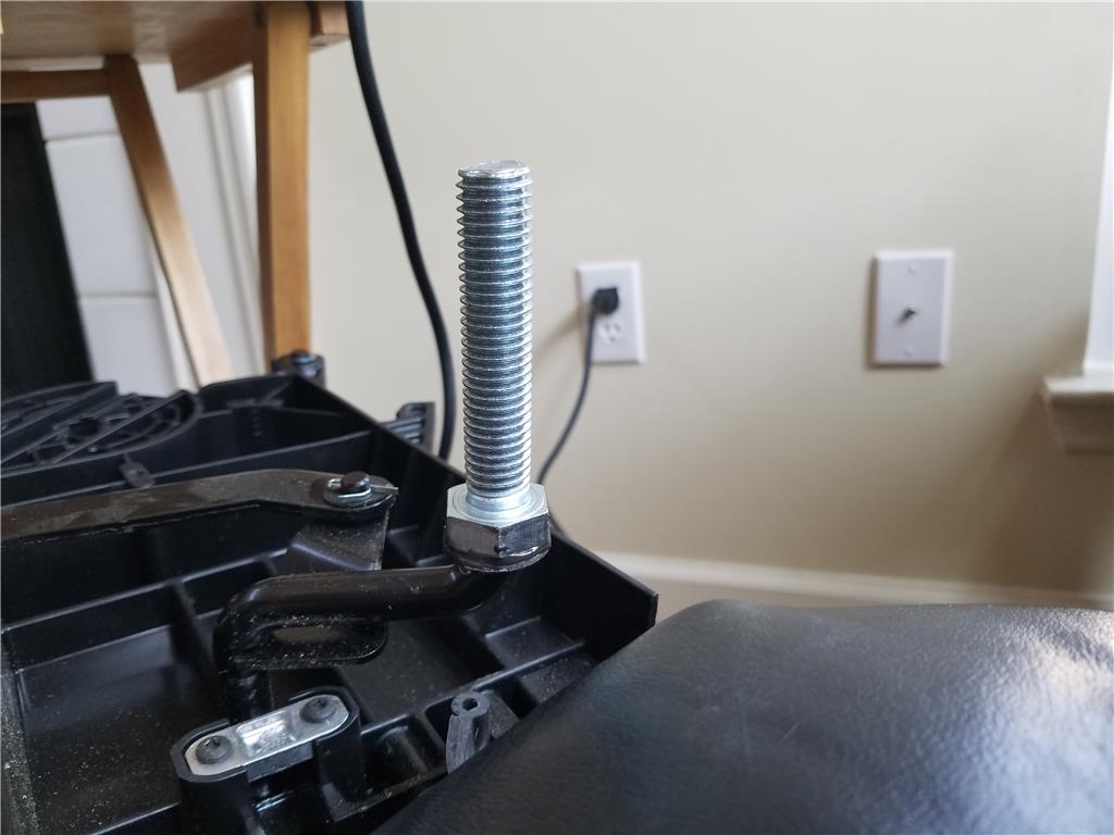
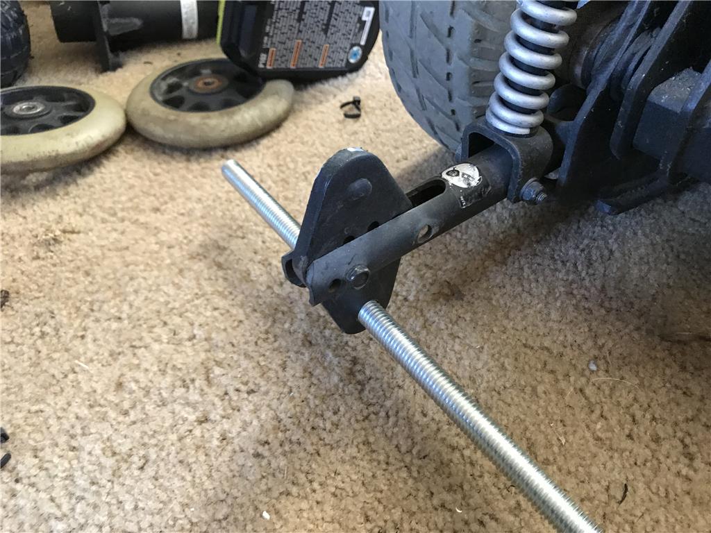
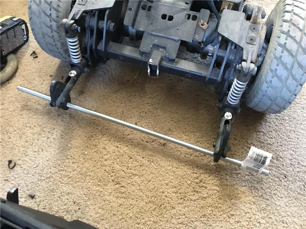
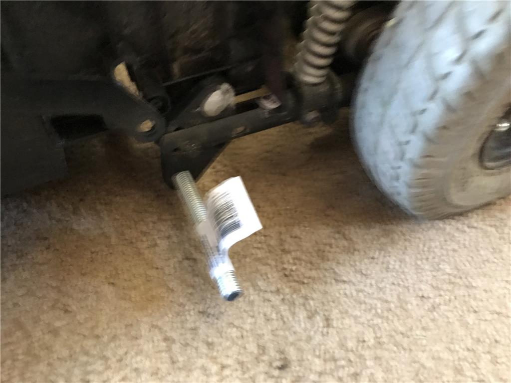
Ok so I picked up some hardware. 1/2" steel zinc threaded rod , nuts, wing nuts and lock nuts. Should be able to basically slide the shaft in or out by unscrewing a wing nut when done. I removed the original axle and it appears to fit in fine.
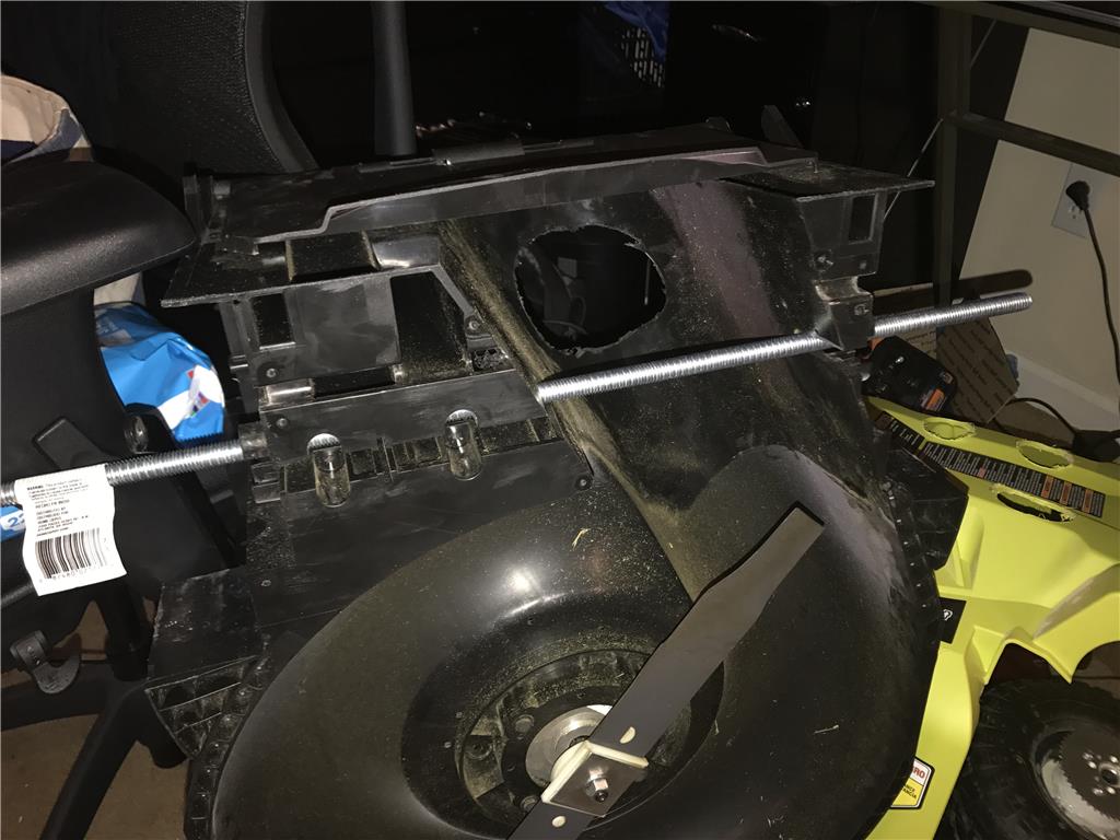
Next I need to pull out the grinder and cut away the center post that is in the way and drill out all the holes the shaft will slide through to 1/2"
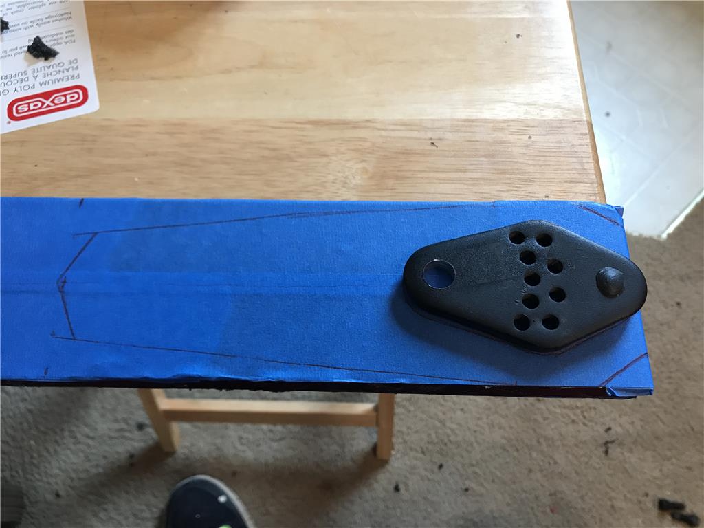
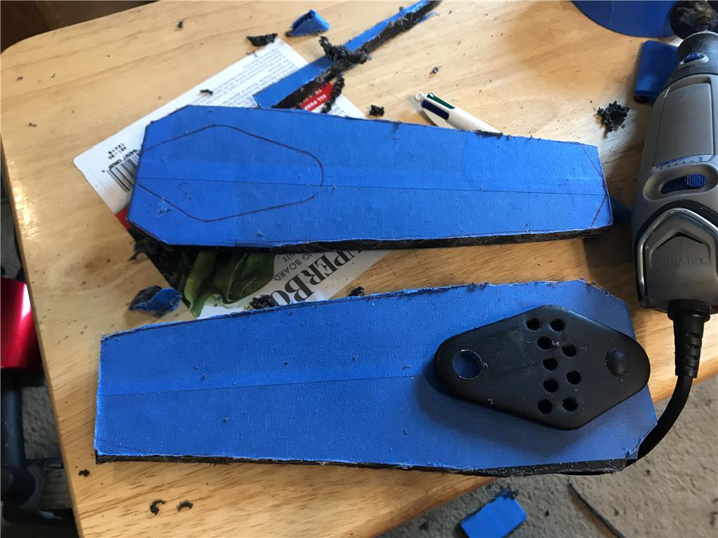
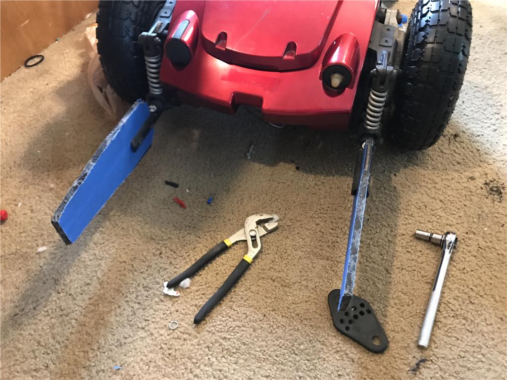
Using the brackets originally for anti tip wheels , I fashioned an adjustable mounting mechanism for the rear of the mower to rest on. The mount can adjust up or down about 2 inches in each direction. This will allow for adjustment of the cutting height on the rear.
I had to use a grinder to remove the studs and the center beam that had the foot rest mount.
Can't wait to see your final creation.
Thanks merne! It has been a learning experience, there were a lot of first for me in this project. I had never used a chain drive before and that was a challenge. Things are more difficult that they look on paper with all the moving parts. I still have about 4 months left of the year grass will grow heavily so I think I will have plenty of opportunities to use it before the end of the year.
Features: Large heat sink design. Supports a wide input voltage 12-60V, 12- 83V wide adjustable output voltage, low dropout voltage.
Specification: Input voltage: 8-60V Input current: 20A Quiescent current: 15mA(12V liter 20V, the output voltage, the higher the current will increase too quiet) Output voltage: 12-80V continuously adjustable Output current: 20A MAX over 15A, please enhance heat dissipation(input, output pressure related, the greater the pressure the smaller the output current) Constant Range: 0.5-20A Operating frequency: 150KHZ Conversion efficiency: up to 95% Product size: approx. 130 x 52 x 49mm/5.11 x 2.04 x 1.92''
OK the above unit I purchased on ebay and hopefully will do what i WANT. I can eliminate multiple batteries by running 24 volts from the wheelchair base batteries and boosting it to 40 volts for the mower blade mower. It uses 6-8 amps according to the specs. This unit is capable of 15 amps and 20 amps if a fan is actively cooling the heatsink.
If this doesnt work I will just use the lithium ion 2.6 amp hour batteries that are made for the mower.
This absolutely must be a labor of love. How much $ do you figure you are into on this project so far?
Hmm well
100 wheelchair base 149 for mower and batteries 40 x 2 for those drills Sabertooth 80 Two new U1 batteries 90 Misc wire 40 8 inch omniwheels 80 each
Yeah it is some money but my goal was the have a better robo mower that the 1000 dollar Worx Landroid for the same or less money.
I didn't mean anything negative. I was just curious, given all the odds and ends purchases what you thought you had in it. Building something like this myself has always been an interest. A lot of DIY remote control examples can be found around but not many robotic / autonomous ones.
Oh no , I dont take it negative. It is a learning process. Learning costs money !
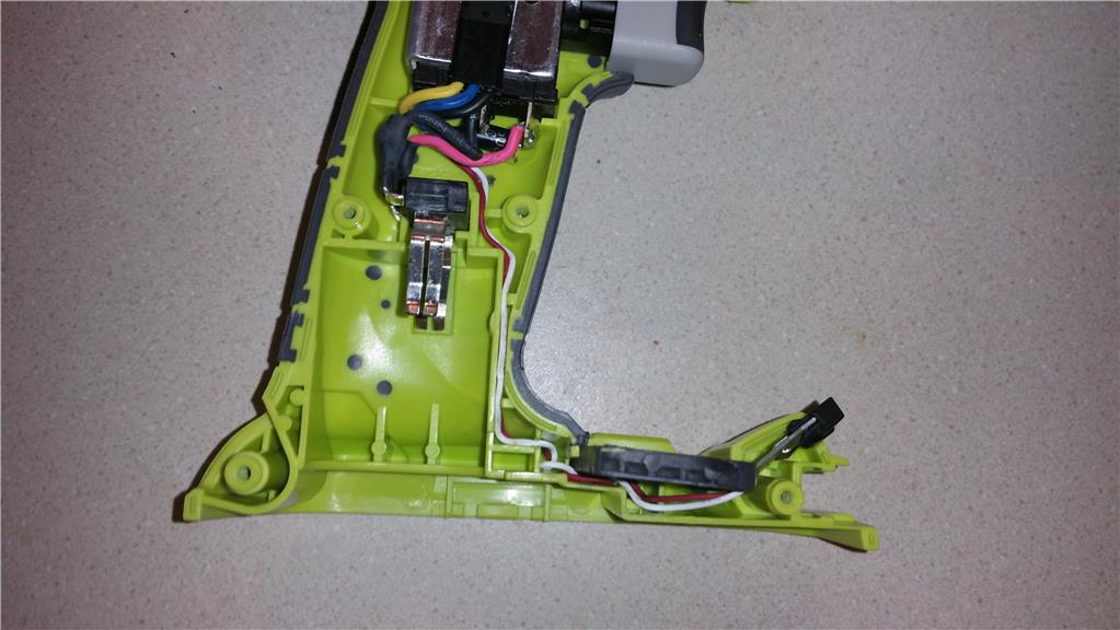
Ok so I stripped down the frame , cut off the footrest and removed the seat mount. I am using corrugated plastic to insulate the electronics from the frame. I wired the motor breaks to release on power up which means they will lock if I lose power.
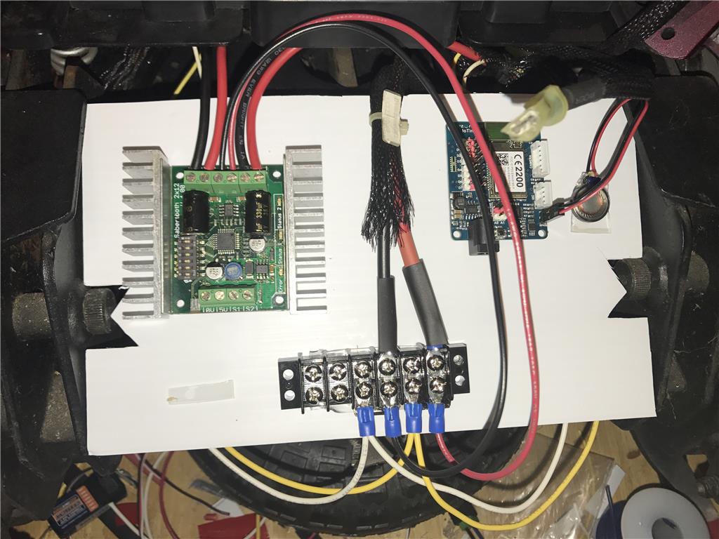
Update, Grr upset at the sabertooth.
I have been trying to use the Sabertooth 2 x 12 simplified serial mode with Ezb tiny and keep having an issue. For example I can click the forward arrow and the wheels roll forward. Great! check. Then click reverse and one wheel turns forward.... what the heck? Similar strange issue when left or right. There are only 4 terminals, so there are 16 possible combinations. So I swapped them around and wrote down the configuration as I go to make sure I had no repeats. I just got more crazyness. So I went back to the original wiring that worked on the forward command and swapped the EZB for a RC Reciever and swapped from Serial 9600 to RC servo input mode and it worked great. To be specific is was mixed control where one servo control is forward/reverse and the other left/right turning. So the only think I can think of is to do a Movement Panel with servos. For now this will allow me to work out physical build.
Any help is great! I need a Movement Panel working with the RC mode since serial is giving me an issue, or if you can think of what the heck is going on with serial.
I don't know if this will help but.......
Are you using one sabertooth for both wheels, one motor for each wheel and attached to a different channel on this sabertooth? Looks like this from your picture. I have this setup for the DC elbow motors of my B9 robot's arms. However I'm not using a Movement Panel but using EZ scripting to send simple serial commands to each channel to move the motors independently. I found that if I send the two serial movement commands for each channel to the sabertooth to fast that the second command to engage the second motor on the second channel won't run. I found that placing a short sleep command between the two serial movement commands helped the second serial movement command to get through. Hope that makes since.
Also (I haven't tried or confirmed this), but if you have two sabertooth's try moving the second motor to the other sabertooth. I have a feeling that one single sabertooth can't process the the serial commands as fast at the EZB can send them and causes the second command to get flooded out. If you split the motors to two different sabertooths then each one can process the command on it's own and as quickly as it's received. :)
Hope this all makes sense and helps.
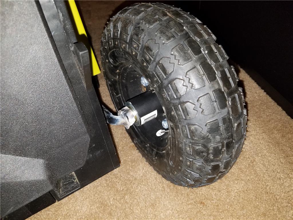
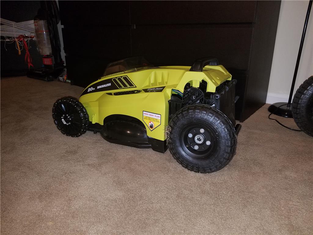
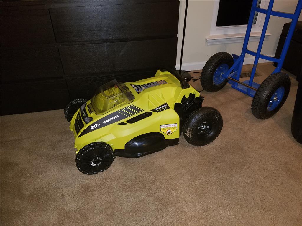
So for 5.99 I picked up outdoor tires with a slightly more aggressive tread. The rim is exactly the same in size. I was able to swap them easily. The only thing that I am concerned of is that the original tires were solid rubber which didn't have much grip. This frame has a couple spots under the motors that are only about a inch or less from the ground. I am considering making cuts to raise the clearance tommorow.
Ok after mounting the tires I took them to the gas station to air them up to 30 psi. They are nice and firm now and I believe these will perform better outside than the solid rubber tire.
Enjoying the updates!
Thanks DJ ! Oh FYI shortly after this project is running I am submitting it to The Home Depot/ Ryobi DIY competition, 2500 grand prize
So I want some more wiggle room between the front of the Jazzy and the back of the mower. This is to allow room for shifting with terrain.
This is thick plastic , .25 inch I believe. It is he same thickness at the steel that was there for the anti tip wheels. I made them extra thick to compensate for being a plastic replacement over steel. I cannot flex this by hand. After dinner I will drill the holes and start bolting things together for an initial test in the driveway.
Ok it has been pouring ran from the tropical storm rolling through so I will do a quick test out on the back porch which is wet and slippery.
Video of first movement tests!
https://m.youtube.com/watch?v=qnpVartMoXc
How did you fix your steering problem?
I switched the Sabertooth to RC mode , mixed servo input. So one servo signal controls forward and back and the second controls left and right. These are mixed by the Sabertooth microcontroller.
https://www.youtube.com/watch?v=bfao-qDu7fU
Youtube video of the first attempt mowing with the bot
Points of interest
-I am still using the 40 v battery packs but the step up converter is going to be installed to boost the voltage from the 24 volts to 40 volts for the mower motor. This will lighten the assembly and also consolidate batteries. two car batteries last a lot longer than a 5 ah battery.
the rear of the mower is sliding accross the grass, I still need to make knotches in the mounts to adjust the height of the mower deck.
I was using this in RC mode and trying to record as well.
the grass was about 8-10 inches tall being cut down to 1.5 inches so the mower could not mow as fast as a normal pass would be.
First person cam will be added so I can mow from inside the house.
Comments and suggestions welcome ! thanks
Lol, nice video. I like the fish tails it gets going so fast. What is your fail safe going that fast and not stoping in time for the cars going by?
Way cool mower. Thanks for sharing.
I have a remote with a dead man switch , if i let go it should stop and apply the brakes, but if that fails I get to figure out what kind of ticket they give a lawn mower robot for failure to yield, LOL
Check this Mower out.
Click To Watch Video
toadi