-635396617587023892.jpg)
In the land of the iRobot Roomba, if you want to turn it on there are presently two ways to do so.
The first way is just a simple button press of the Clean button. Or, one could use a IR remote control to also accomplish the same task. Neither choice is needed when using an EZB controller and three of its Digital ports.
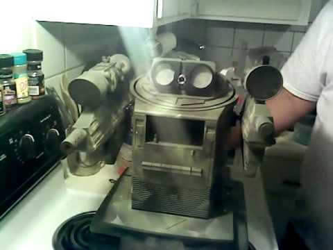
In order to perform the EZB controller option a little pre-design work is required. It involves using some 26 guage wire, a soldering iron and three neat little 5 volt powered relays. The electrial wiring connection is done by soldering a pair of wires across the Clean button contacts located on the printed circuit assembly inside the Roomba that are then connected to the Normally open contacts of the 5 volt relay. Then all you do is wire the signal (White) wire from the digital port of the EZB controller to the activate port (CH1) of the relay. The relay can be turned on by a high (3.3vdc) or low (Gnd) pulse provided by the digital port of the EZB. The voltage reference (3.3vdc, or Gnd) lead is wired to the CH1 port and that will activate the relay. In the example presented in this description a high pulse that lasts for 1 second will accomplish the Clean button press to turn on the Roomba. Now, all the preceding verbiage was needed so that the Roomba is powered on and the Serial Command Interface (SCI) is able to receive serial commands from the EZB controller.
Here is a start up script that will turn on your 500, 600, 700, or 800 model Roomba.
set(d1,off) # start in the off condition set(d1,on) # This will operate the relay and turn on Roomba sleep(1000) # replicate a 1 second Clean button press set(d1,off) # release relay
Now the Roomba is ready to receive serial commands.
Additional electrical connections were also made to the Spot button as well as the Dock button. With the proper sequence of button presses the Roomba can be placed into the Built in Test program and all of its sensors can be accessed and tested for proper operation.
DJ added the UART Serial terminal to the ARC GUI that can be used to actually monitor the individual diagnostic test results on all the internal Roomba sensors.
-635396587467336392.jpg)
-635396587892023892.jpg)
Other robots from Synthiam community
Jstarne1's Meet Rc-Xd Airsoft Droid Dual Wield Gunner...
Hoolagen1's Pics Of Progress.......

Awesome Doc, good to know when I start messing with later versions of the Roomba... The 400 series Create is much simpler....In a much more basic way, I am able to remotely turn my Create on and off via pin 3 of the 25 pin connection port on the Create... I just toggle a digital port connected to pin 3 of the create and presto, I can remotely turn the create on and off at will...
Richard R, you can also put your Create into the Built in Test mode and check its sensors and motors for proper operation. There is a lot of ASCII text output from the SCI port that will give you great detail about the diagnostic test results. After exiting the test program the same SCI port will output the charging report once per second when the Create is connected to a home base or power supply. All of those reports can be captured using the UART Terminal in ARC.
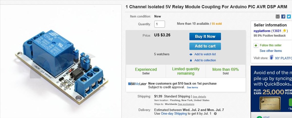
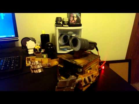
here is a picture showing the 3 relays used to control the Roomba using script commands via the mounted EZB(4) along with the 5 volt regulator and LI-ion power.
That's cool Robot-Doc, I may eventually have a use for relays. Do you have a link? Thanks, Steve S
Very impressive. I can see how this will help lots of people.
Steve S, here is the URL Link
This is a good design since it is Optically isolated from the EZB controller.