


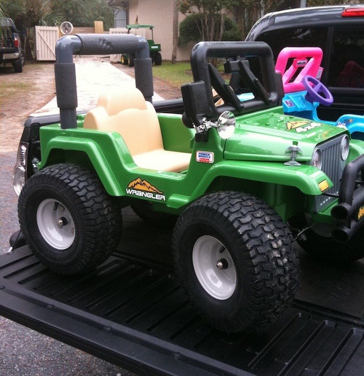


Hey Community , i really don't do enough fun projects. As you may notice many of my projects have a utility function. Squeegee mops, jarvis vacuums, smart marine fish tank is... well smart lol. So this is just for fun and I hope others enjoy it. I have already contemplated using it as a demonstration tool to get kids interested in technology. . Dang it! This is just for fun , ok I'll try not to get to serious with this. My friend Marty was talking about being able to drive the power wheels around while his kid was in it around the neighborhood. Or if his kid was driving and got to far he's just a button click away from stopping it. We found a free power wheels that had seen some rough years and we gave it a complete makeover. It looks better than new, new Gel cells from power sonic , smart charging and more. I gave it a cool high grass stripe camo.pattern and gave it to his son for his birthday. I'll post a couple pics. He's on the fence about doing the further mods so i searched craigslist.org for another power wheels that had been loved a little too hard. Searching for something with space and power I wanted I set my heart on a f150 , Toyota 4x or jeep 4x4. I didn't find a 4x4 model but f150 was the next best as it had dual gearboxes with rs585 motors. Also a good gel battery and charger was included. Here come some pics...
Other robots from Synthiam community

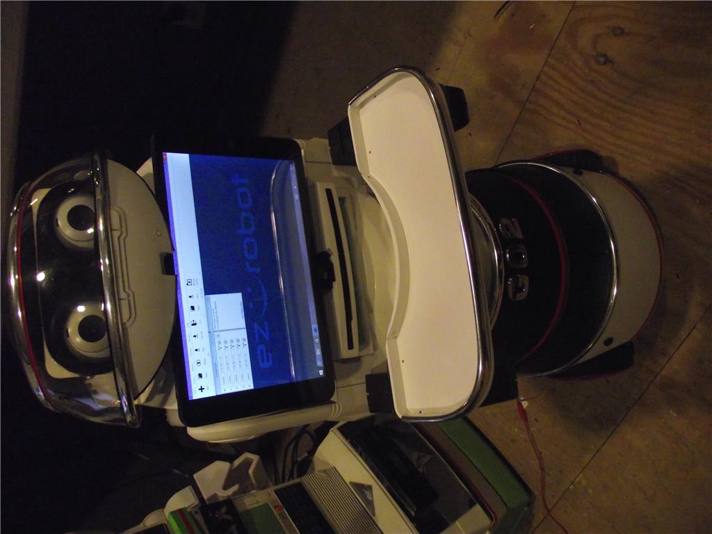
Athena's R2D2 Testing
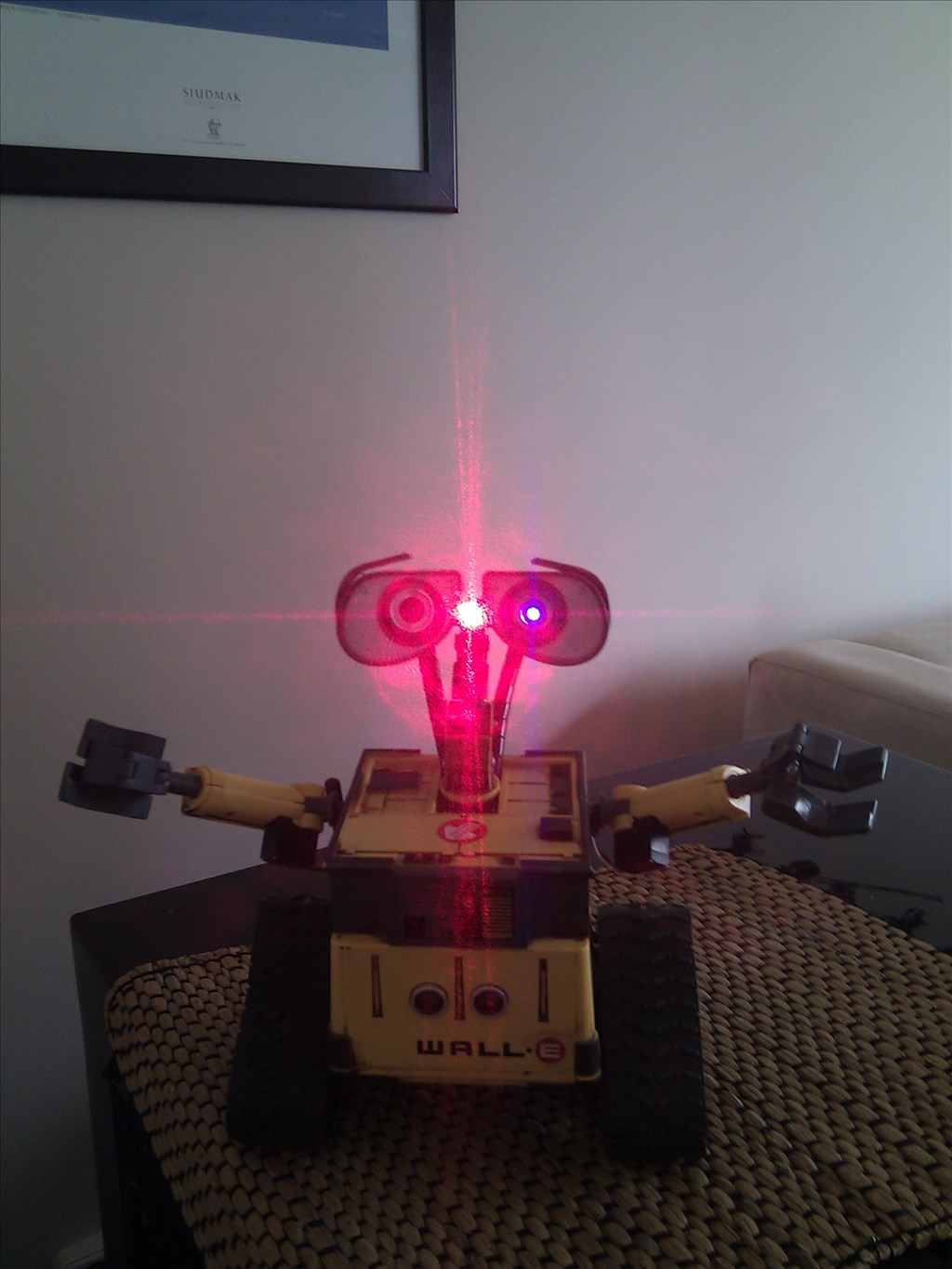
Fisha's Wall-E Wall-E From Poland - Tribute To My Newborn...

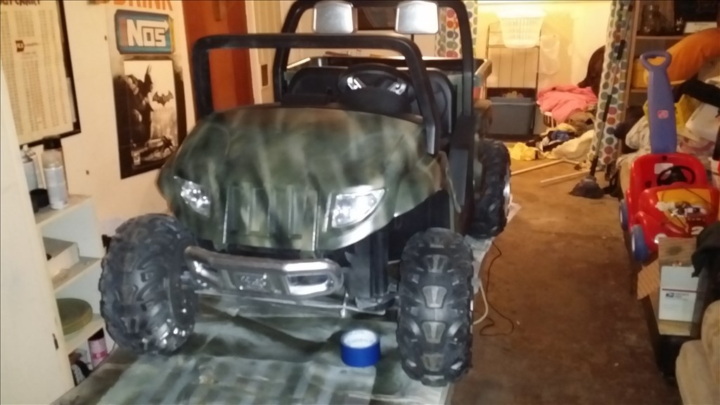
Here is Marty's Power wheels , before and after. He's on the fence about doing the mods but I'm betting that doing the f150 will make him want to finish it. He he he.
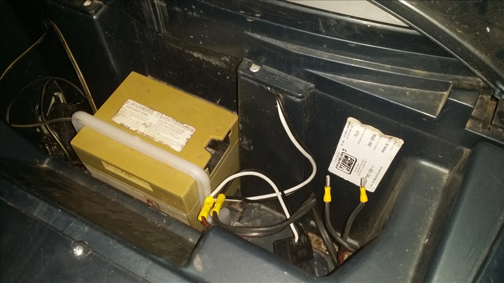
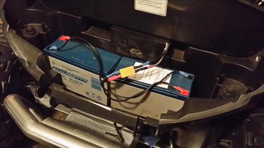
Electrical needed some love. Take it from 6 volt standard to dual 12 volt gel cell power sonic batteries. Turnigy XT 60 gold connectors were soldered onto 12 guage wire and covered in heatshrink.
Ok so here's a sneak at marty's machine, I will update this thread when we start adding electronic hardware like motors controllers ect.
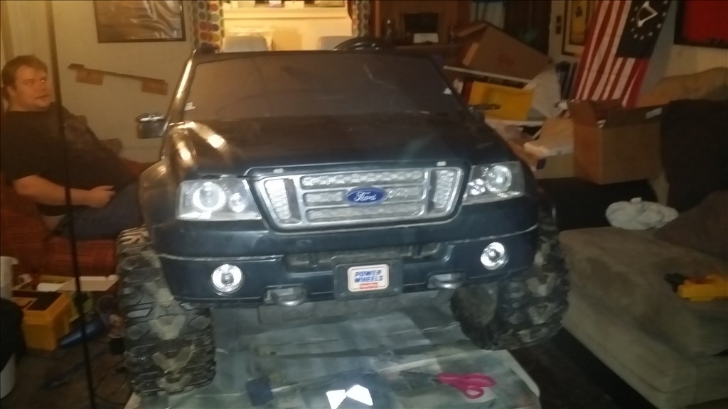
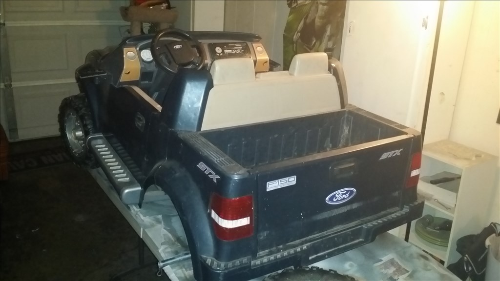
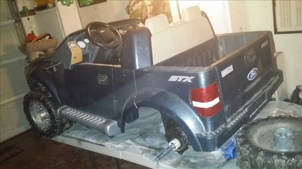
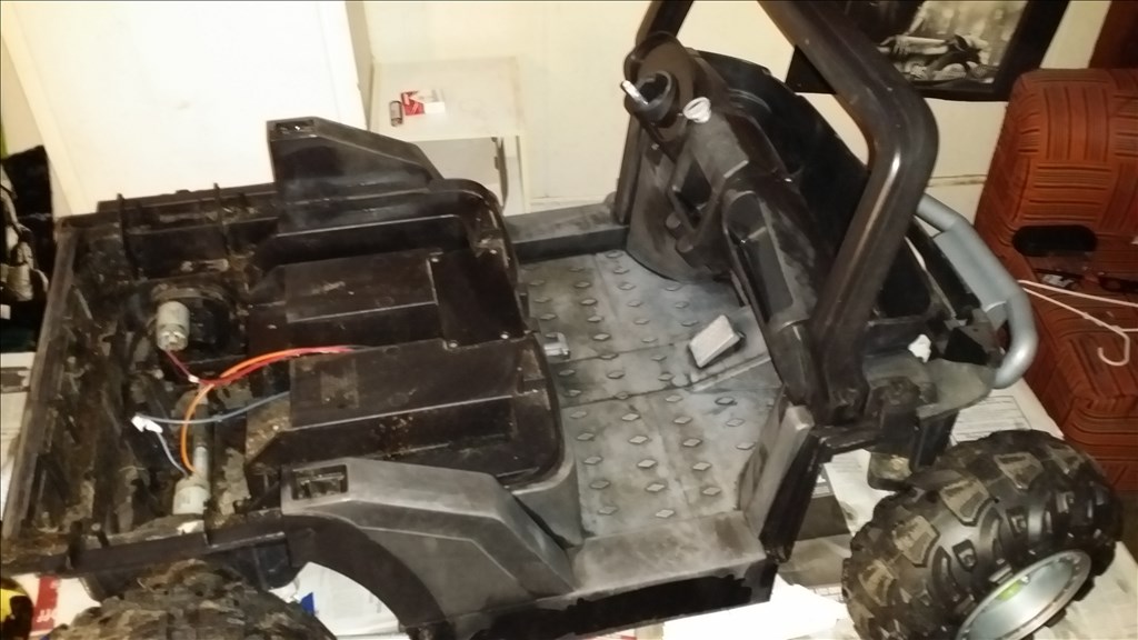
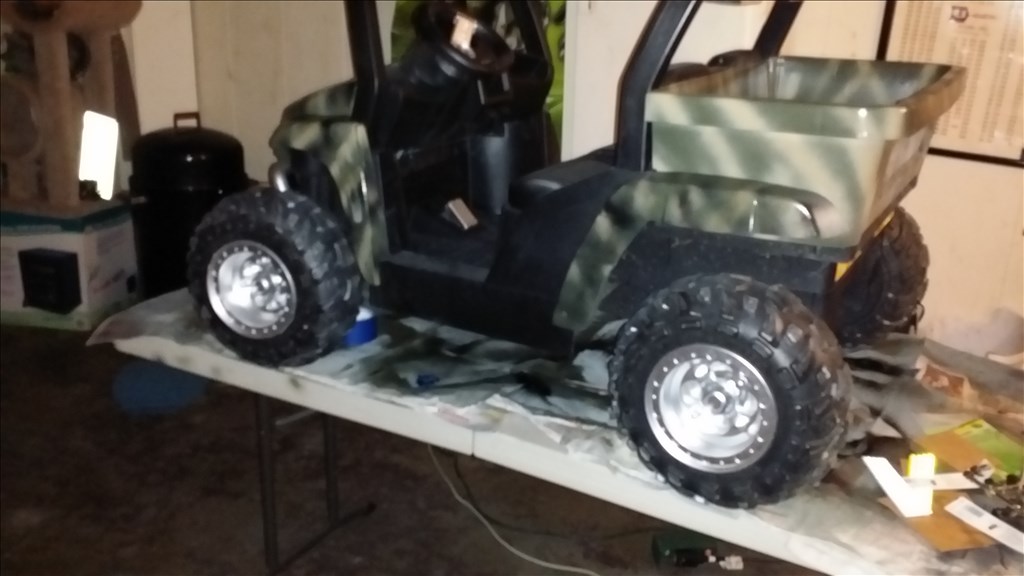
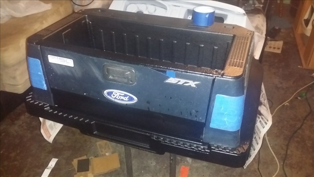
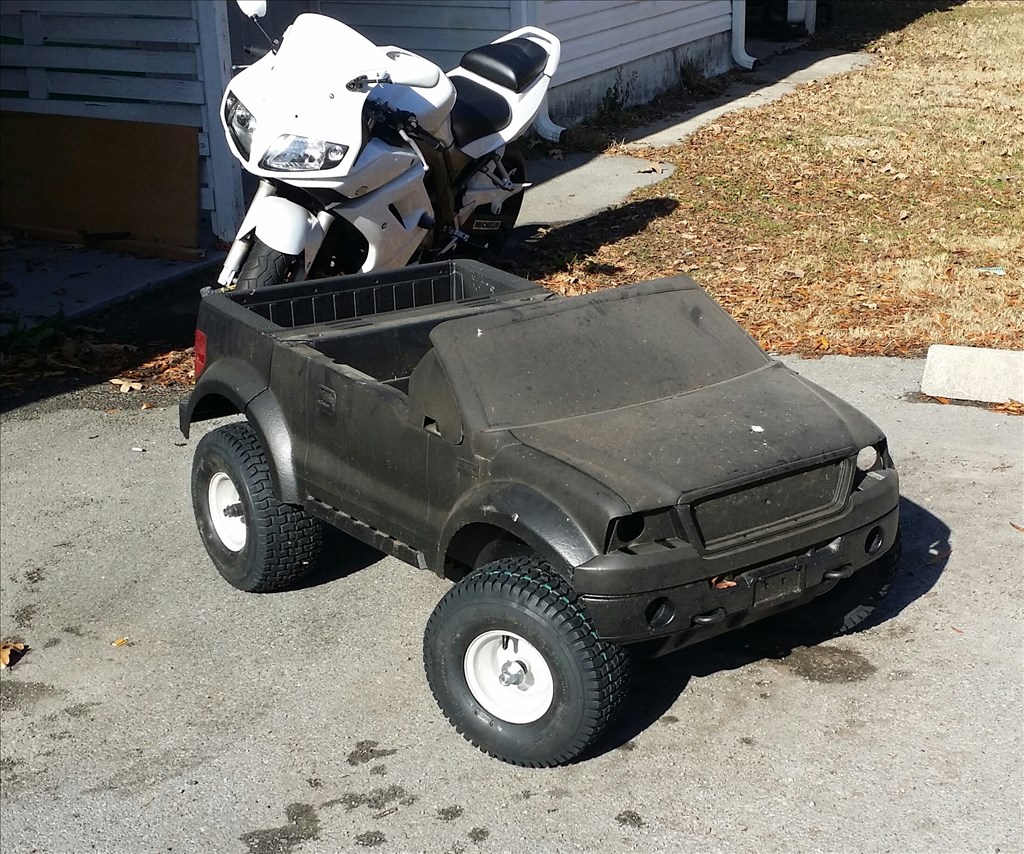
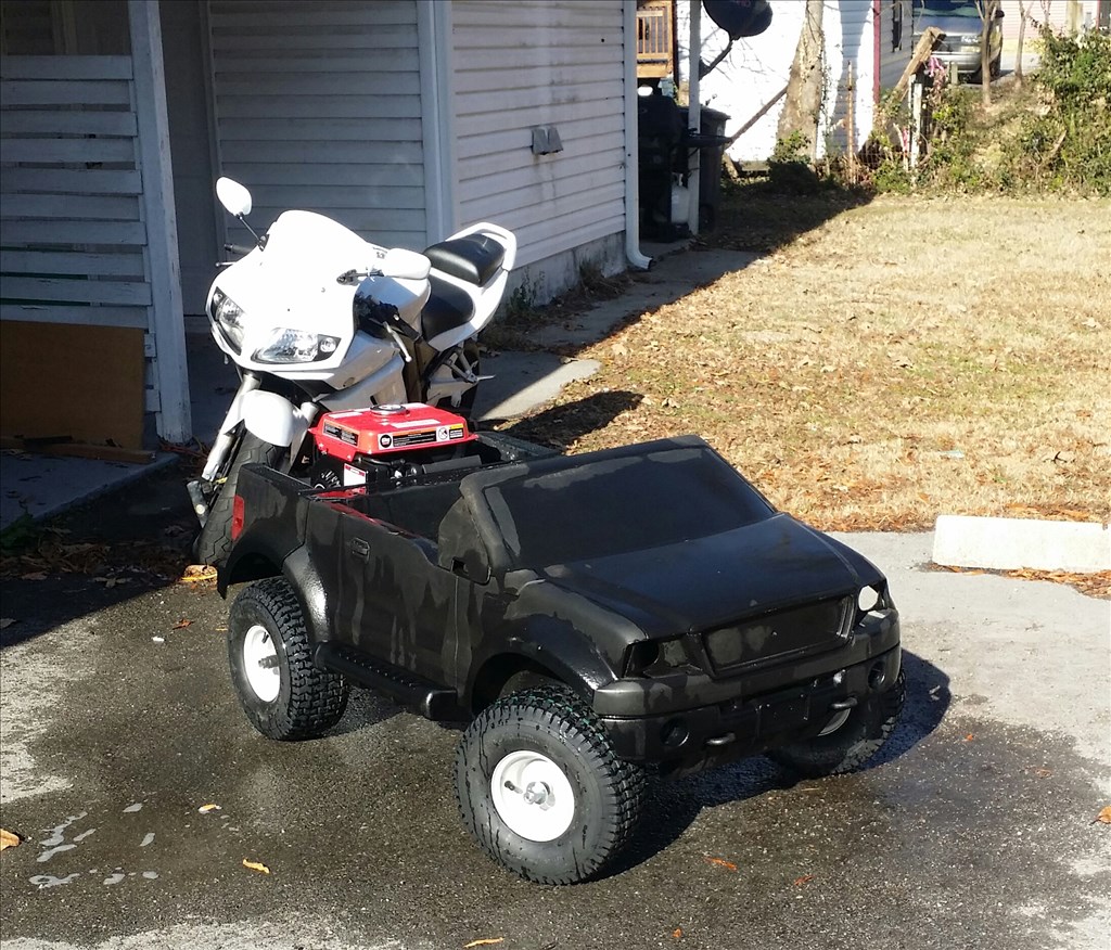
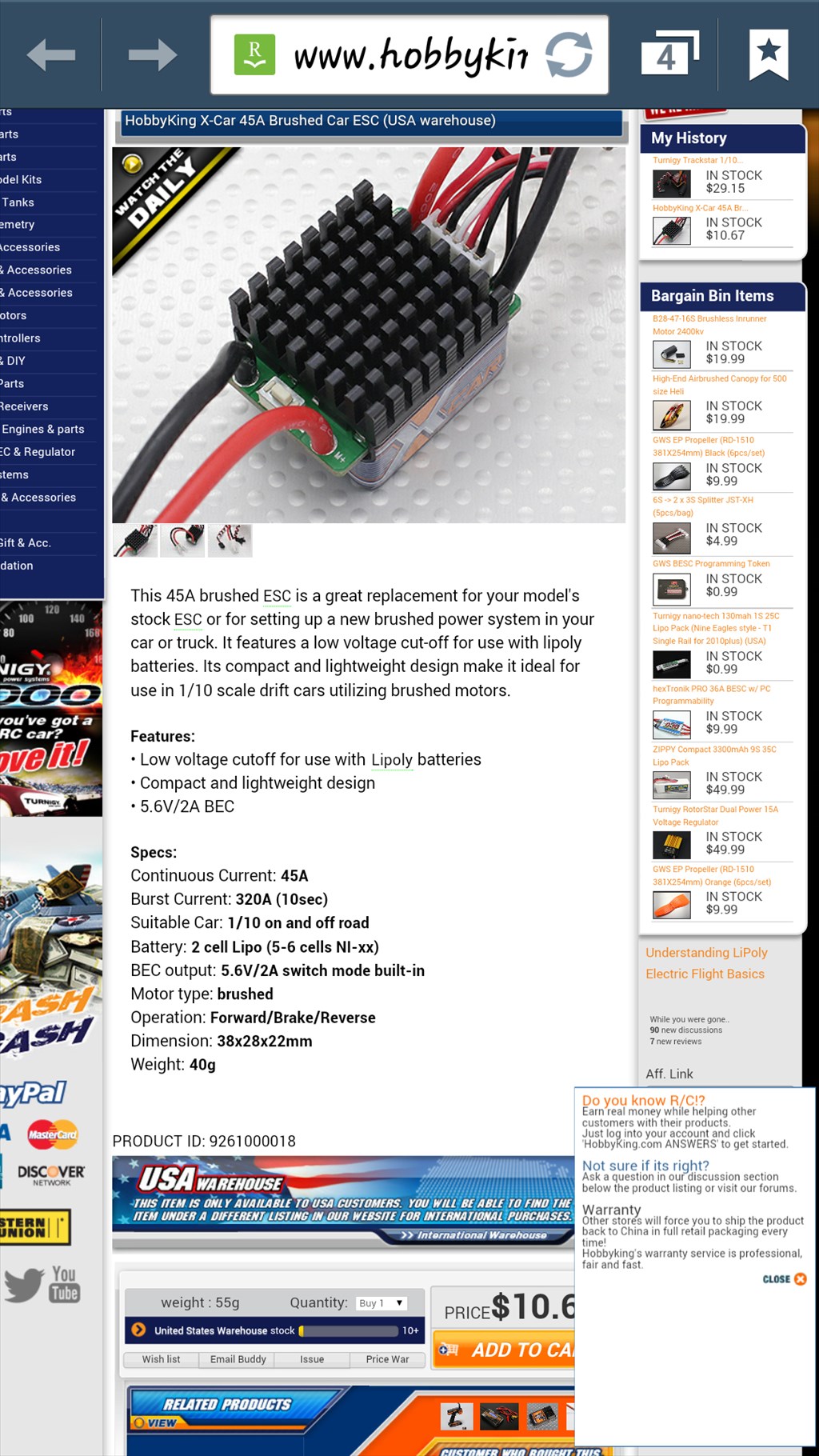
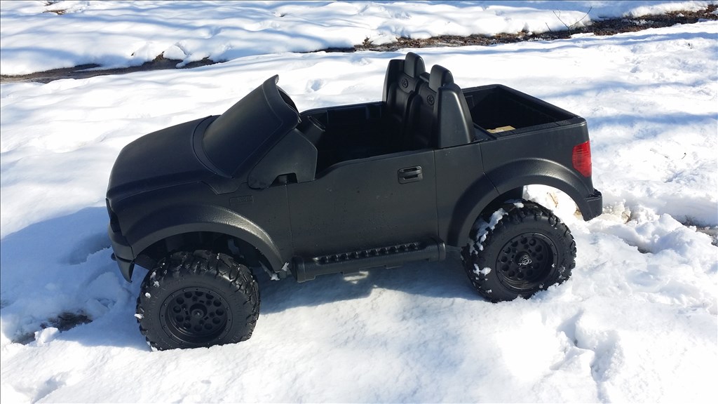
Ok here is mine, the Power wheels F150 series donor from Craigslist.org. I paid a hefty $40 and had to pick it up in my hatch back.
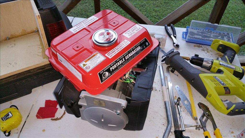
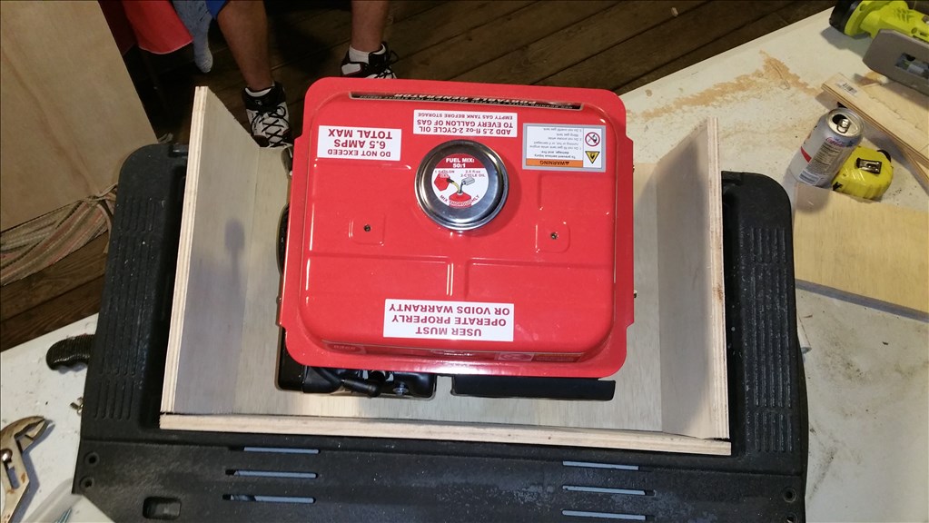
Yup I'm pretty sure we are gonna ignore that warning , safety first! .... well ok maybe second.
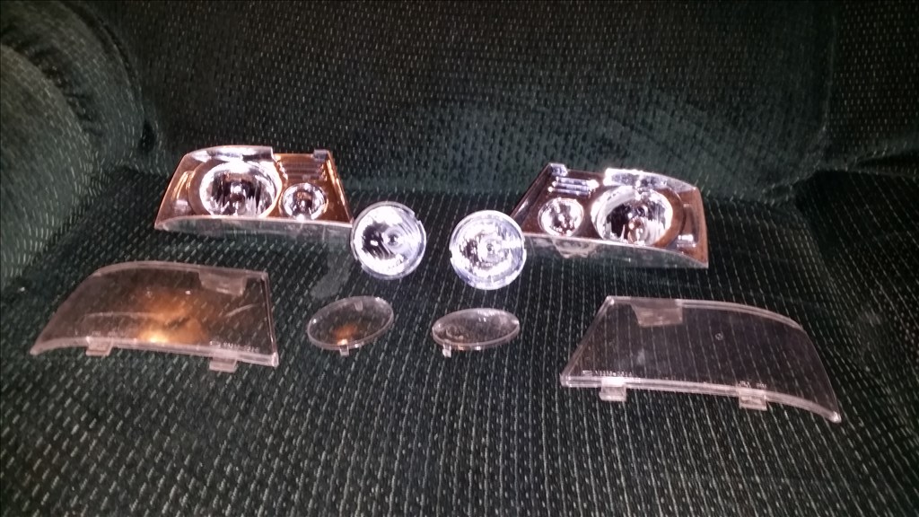
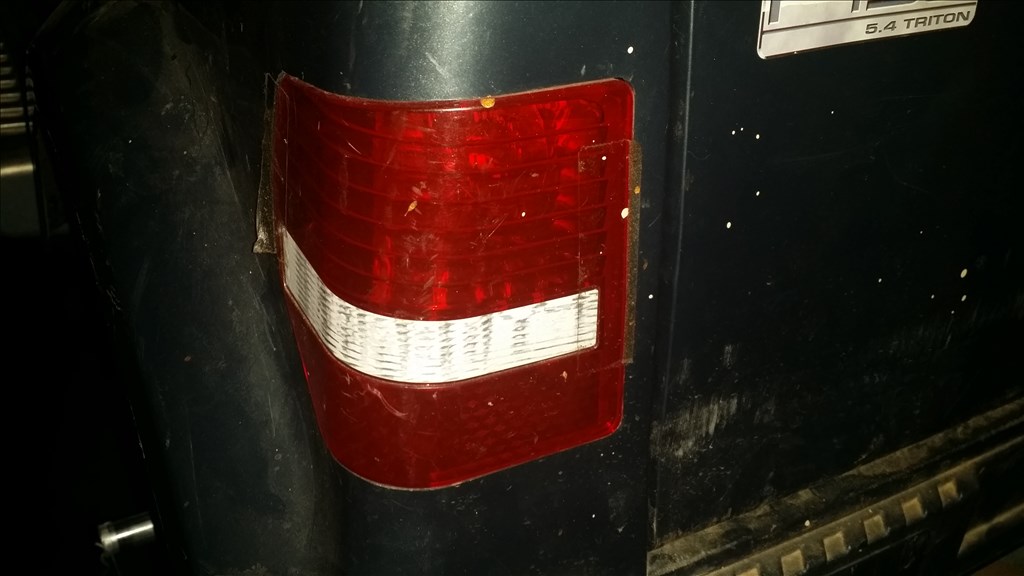
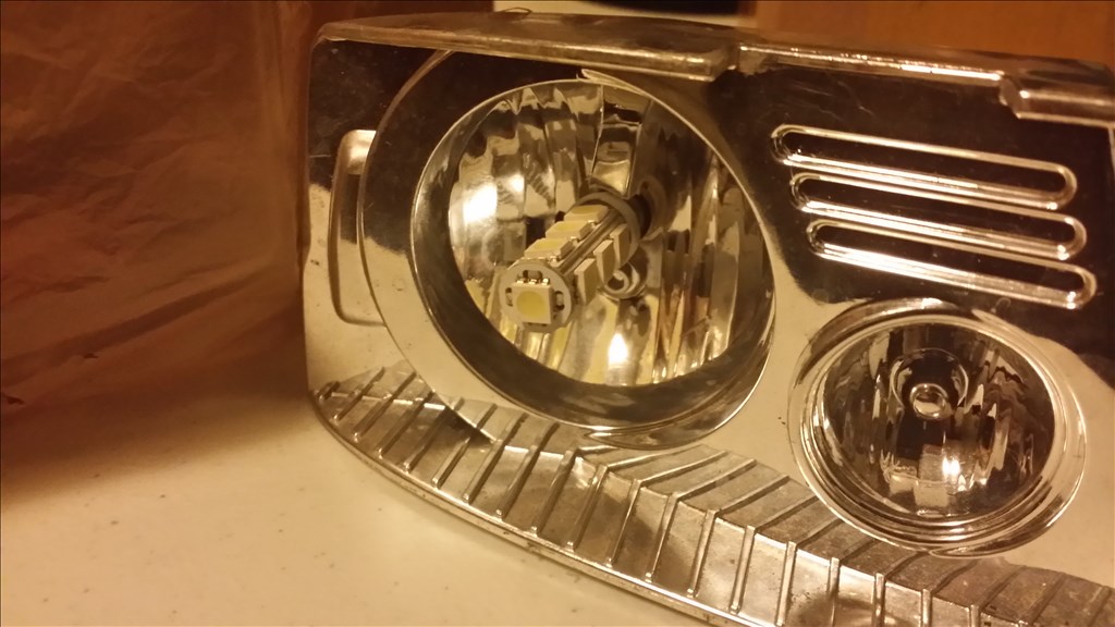
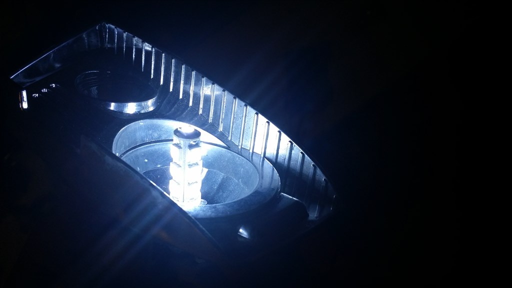
Something I realized is that the fake headlights and fog lights looked very convincing. I held a flashlight bulb in the reflector and found they worked pretty much like a standard round headlight. So while I had them out I'm drilling holes in all the reflectors so i can fit 300 lumen led. Led 1891 bannet socket bulbs. Just for testing I have some 25 lumen standard filament bulbs. Because I already know I can mod one of my cams to see excellent at night I am tempted to find a reasonable location for IR Illuminated strip or circle. So with one button press I can go dark and run around with very little light. This sounds like fun. The tail lights also look like they could be functional. It will never be a road vehicle but being able to turn the running lights on will make it easier to see if it gets out of sight or stuck and needs some manual assistance.
Here are some specs for the 1/4 scale F150
maximum recommended rider weight 130 pounds
1 Year manufacturer bumper to bumper warranty and box dimensions are: 35.875 x 29.875 x 51.5; weight: 92.1 lbs
The vehicle drives 2.5 and 5mph forward and 2.5 mph in reverse
Dual Independent DC motors with gearbox on a solid galvanized steel axle in the rear
Front Rack style steering with galvanized steel spindles and steel tie rods.
Background of Power wheels modifications and competitions
I will also be posting the Power wheels awesomeness on a power wheels forum. Apparently its a lucrative hobby. Maybe people mods these things for competition, racing and even just for fun at car shows. I have seen many RC versions so EZ robot can bring a different angle to this "sport".
There are even clubs and competitions where power wheels are modded to be controlled from a computer and have a "gun" mounted on them to play a sort of laser tag with other competitors. Two man teams with one driver and a gunner portray a scenario of driving a HALO Warthog ATV. If anyone already didn't know HALO is a popular video game that has spanned more than 6 game releases for Xbox branded consoles worldwide.
Makerfaire Detroit has modified races http://makezine.com/2010/03/26/power-wheels-racing-competition-at/
Generator Stalwarts http://ithacagenerator.org/generator-stalwarts-to-compete-in-power-wheels-competition/
http://jalopnik.com/5601754/power-wheels-racing-fat-men-on-souped+up-toy-cars
http://ecomodder.com/forum/showthread.php/modified-powerwheels-racing-fun-12957.html (by the way there is a banner at the bottom of this website for Ez Robot, first ad i have seen)
http://mods-n-hacks.wonderhowto.com/inspiration/mod-your-power-wheels-into-wifi-halo-warthogs-0113812/
http://www.youtube.com/watch?v=sJDjQKR0kpg
PDC09 Makerspace coding for fun
I thought this was cool, we already have two, now im wondering if there are any maker spaces or hacker spaces have modded Power wheels they can operate remotly. It also would be cool to try to do some point a to point b autonomy but lets get it manually controlled remotly though wifi and then we will go from there :)
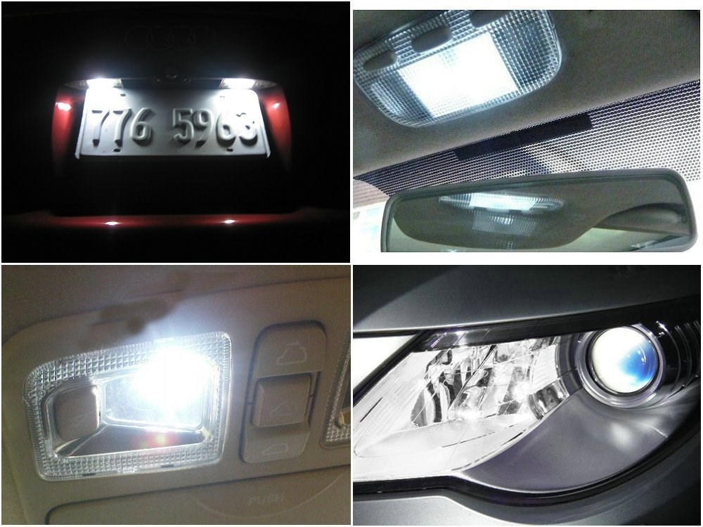
I have Ba9s LED bulbs on the way to replace the temporary basic bulbs I picked up from radioshack. They are low current draw, and have high lumens for a small bulb. Since no one is really riding in my power wheels the lights are to illuminate the drive path so I can see well with a camera at night. Led bulbs always look much cleaner as well. Everyone knows I like my projects to look cool when possible.

So far I am thinking 4 headlights and 2 tail light bulbs.
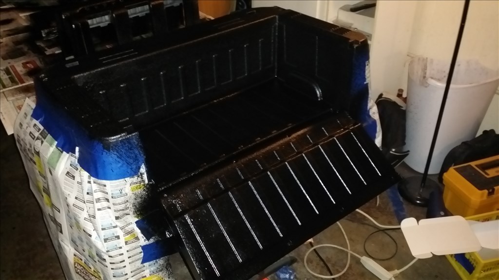
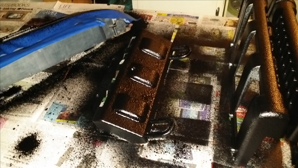
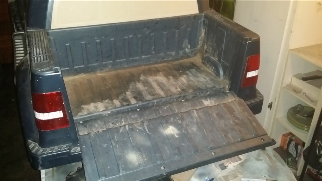
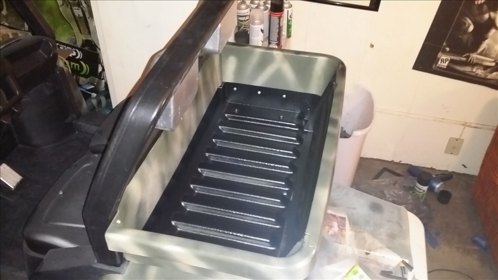
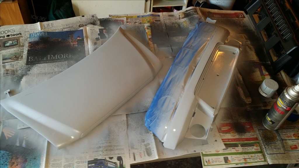
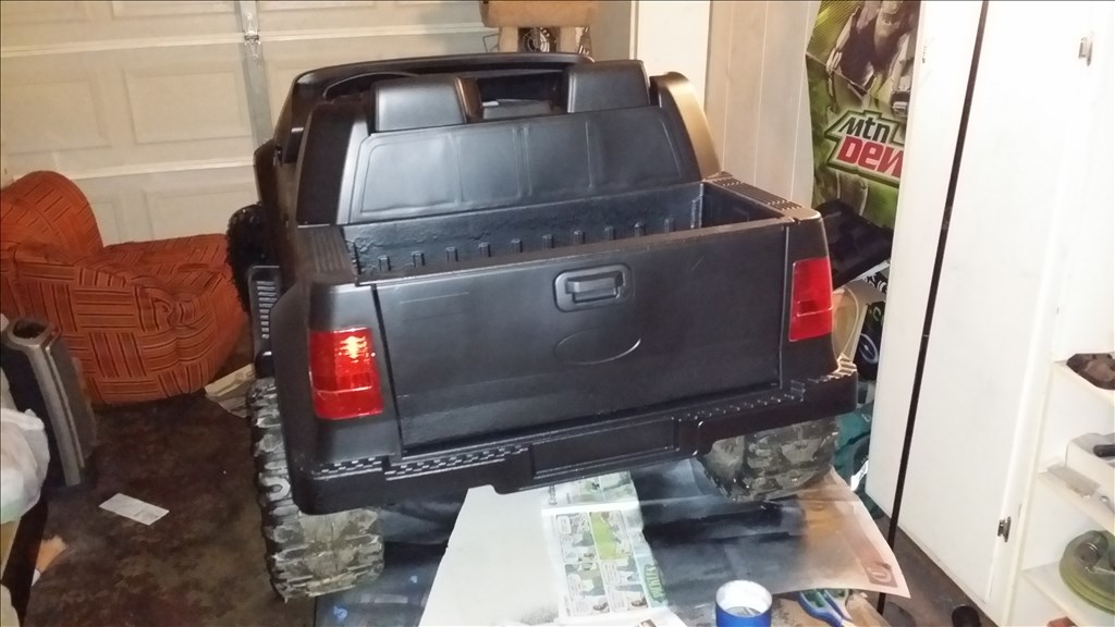
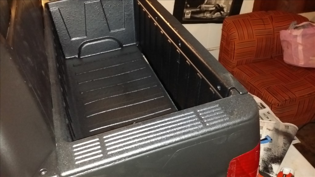
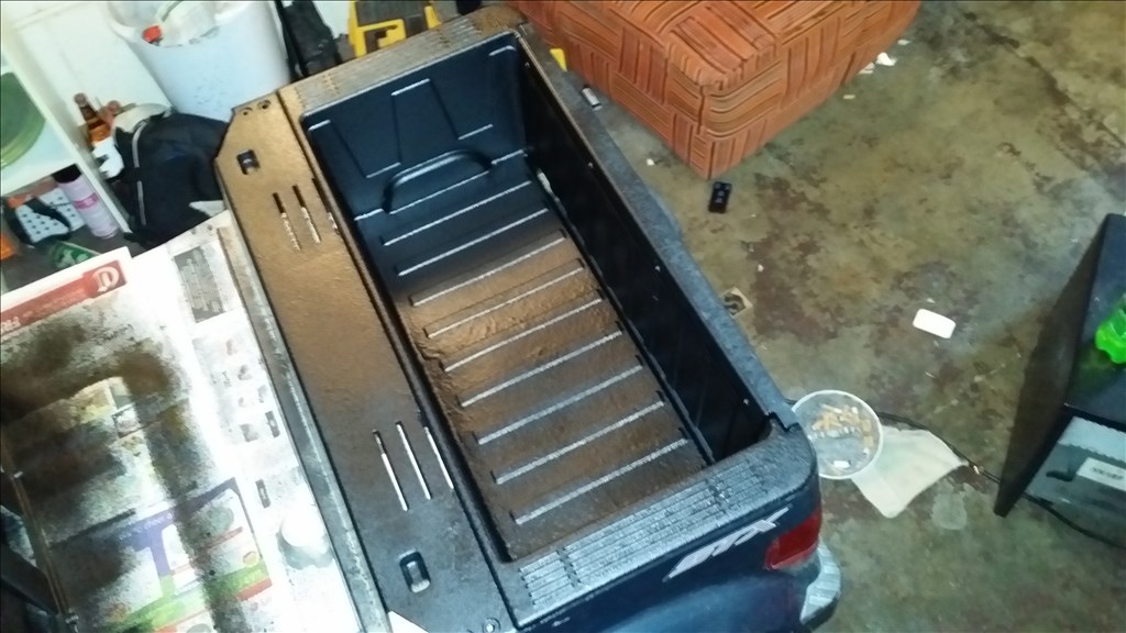
We tore down all the major parts last night and tonight I cleaned the brush guard , side guard / sliders , the front bumper and the truck bed portion. I sprayed them down with a liquid rubber sealer that looks similar to spray in truck bed liner.
Ok so this stuff goes on really thick and takes a long time to dry , if it is cold it can take more than 24 hours. We are in a garage and have a space heater going so hopefully we can get it up to 50 to 60 degrees so it will be dry tommorow. Basically the idea is lower edges of the truck will likely be scraped often whether it is from loading or unloading or just rock, sticks and things like that. So these high risk areas for scratches I'm coating. This is c all ed rubber flex seal.
I'm looking at some real tire options as the truck has more torque than it does traction due to the hard plastic wheels. Looking at other projects using lawnmower designed wheels and tires work well.
Man thats gonna be bad ass! Check out www.highlifter.com Throw some outlaws on that bad boy maybe even a lift kit! lol
Wow, nice lines & lights. :)
Did you do that all in one day or just post all the posts in one day? You're a busy guy.
That was two evenings , there's lots of drying time involved which makes things go slower. The electrical takes a couple hours to solder up all the wires and install new batteries , I'm working on it more today.
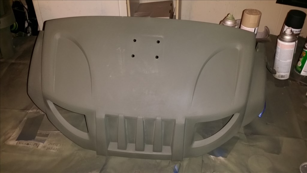
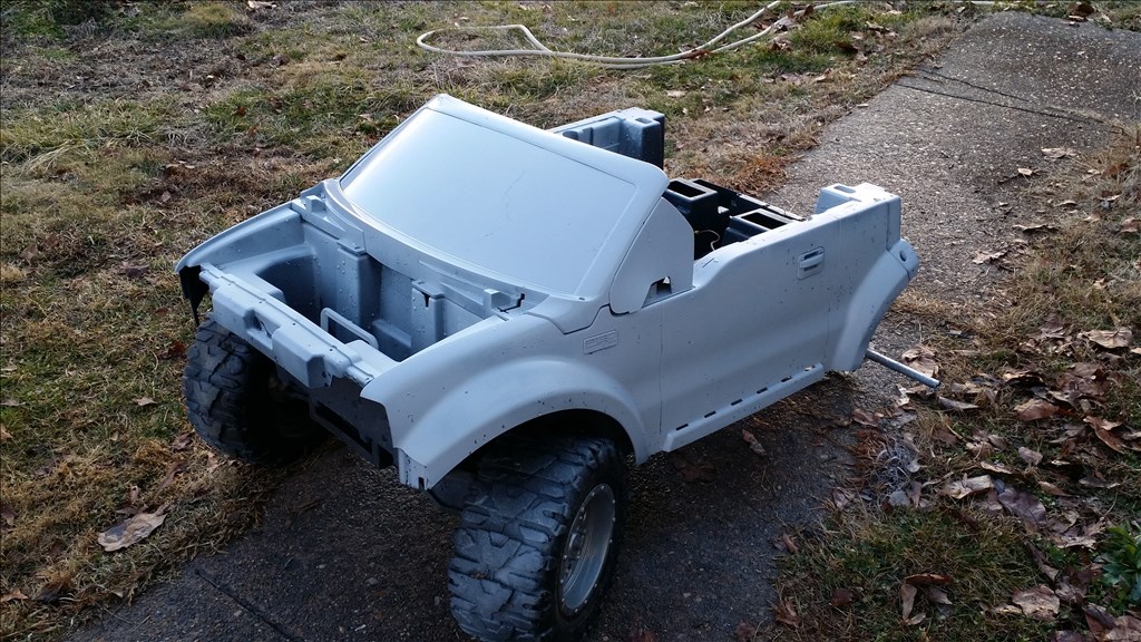
Today the rubber coated parts have hardened and look good. Now I'm priming the plastic parts so i can see major imperfections easier. I will sand them and then move to paint.
I pulled the frame outside and washed it with hot water and dish soap. Then drilled a few holes in the floor so it's easier for any water to drain out.
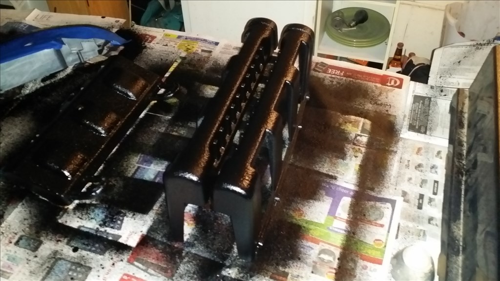
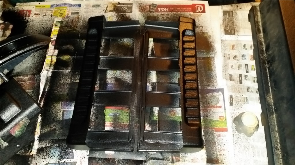
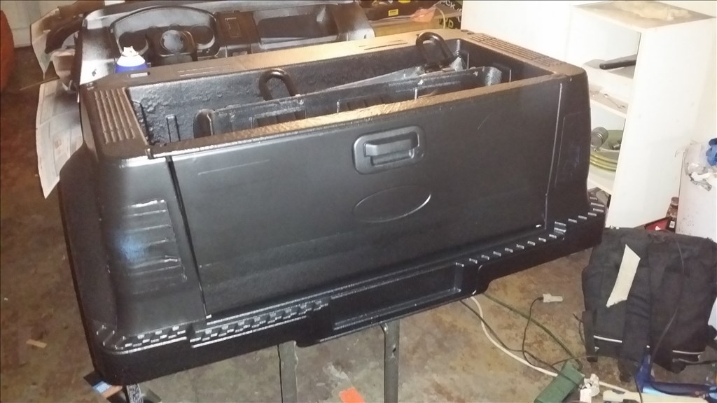
Here's the finished parts with rubber coating.
Looking good! I think this could be an awesome project. What about a robotic driver too?
Adult Power Wheels Racing
First robotic contestant?^^
https://www.youtube.com/watch?v=rNY9Dx617N8&feature=youtube_gdata_player
Plastidip option looks simple. :)
I am considering different options but I think stealth looks really cool too.
@Technopro , lol I have no intention of riding this thing lol. The sport of adults riding them looks like I need to sign a waiver, get a tetanus booster shot and buy some life insurance lol. I will enjoy it at a.safe distance through a PC or android device lol.
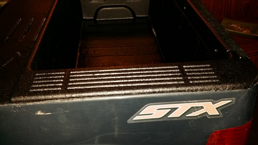
Taped off and rubber coated the reason bumper and part of the tailgate that looks like it rubs against something. I want to cost the areas most likely to get scuffed with this hardy thick rubber.
Holes are drilled for the 850nm IR Leds. I believe this is 48 leds scattered.
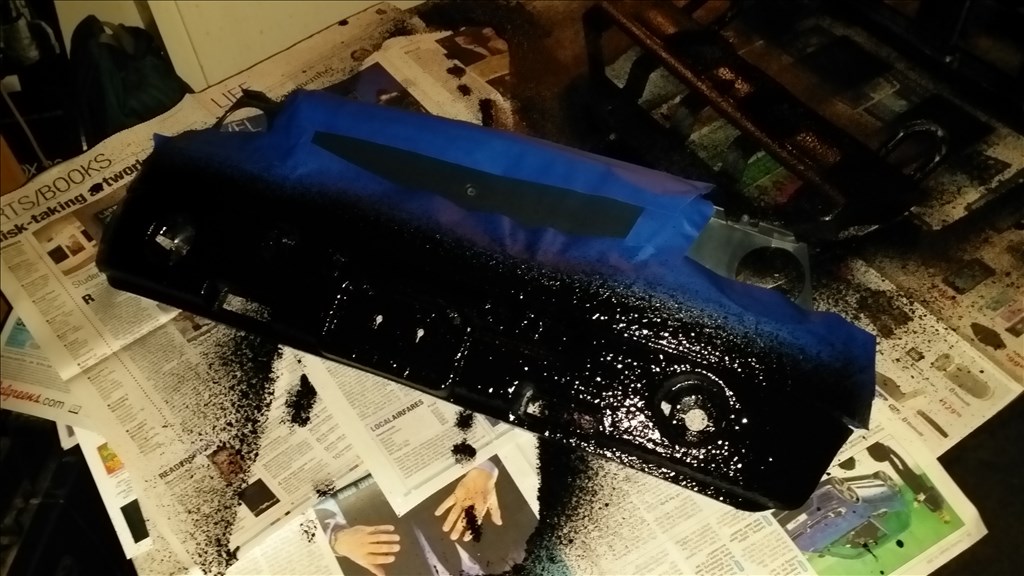
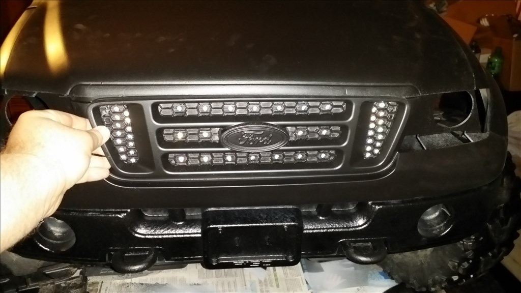
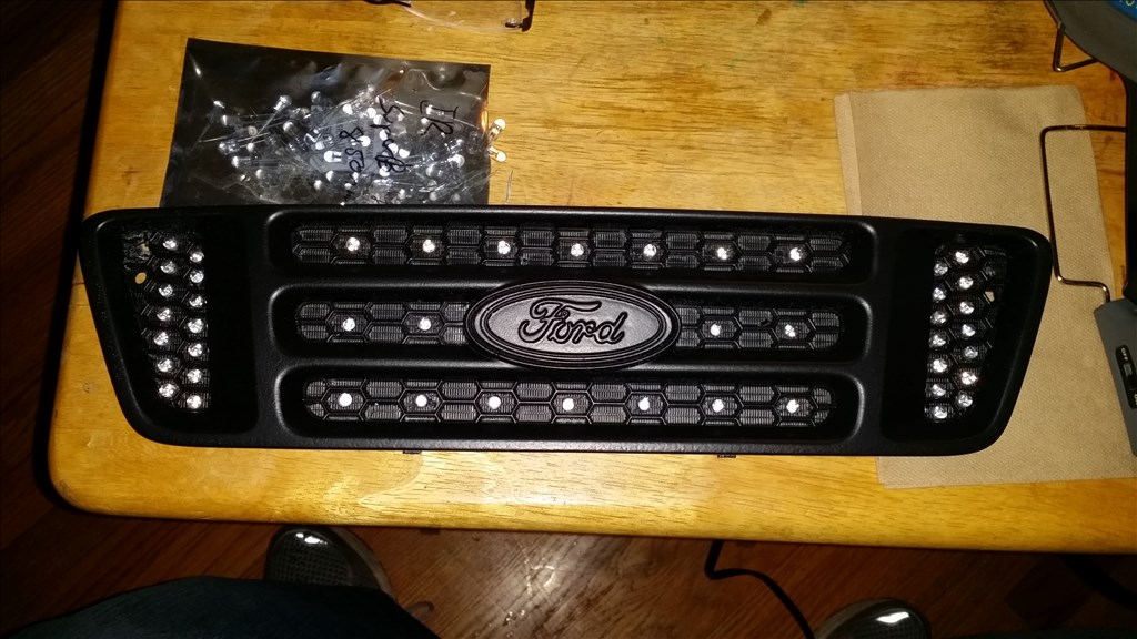
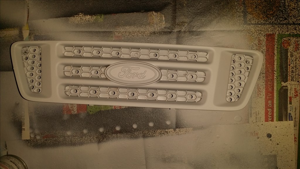
I found plastidip in spray can format and tried it on the grill.
Here is the grill , predrilled with 48 holes for 850nm leds. The grill will be like a giant illuminator.
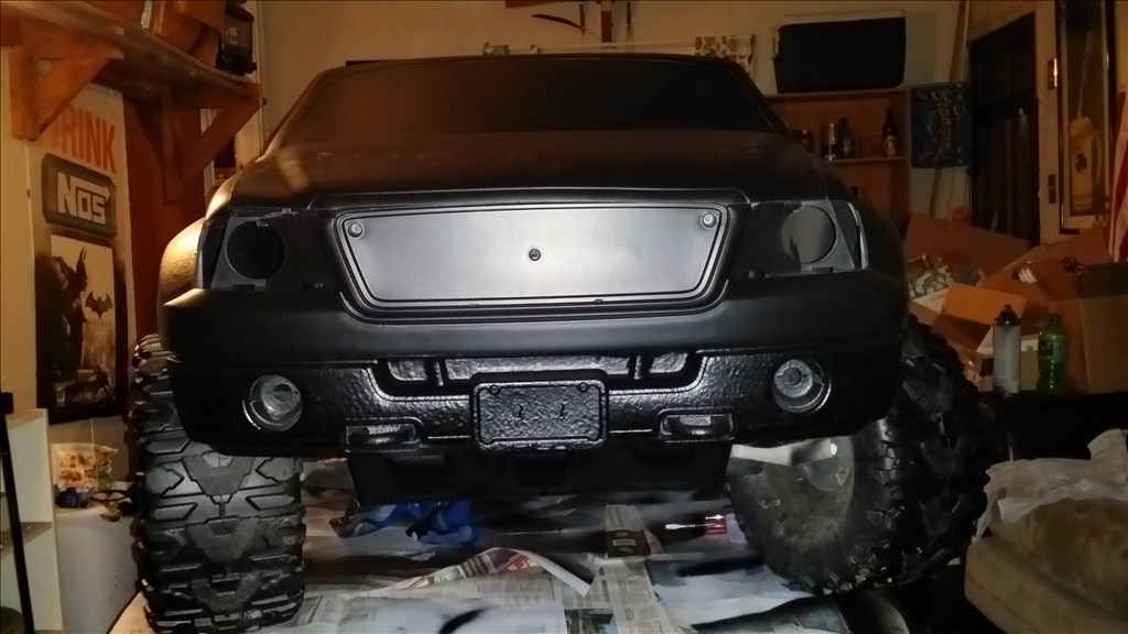
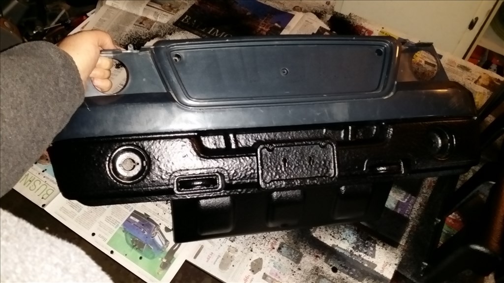
A 3 inch lip all the way around the vehicle was coated in the hard rubber sealant , the grey primered area will be plastidip coated just like the grill. Very stealthy looking I like it.
awesome color. i wouldn use paper do.it absorbs paint and can leave marks behind it.
Thanks bud
The rubber spray is so thick the paper doesn't absorb it at all. It should be a descent. I don't believe the project will have any runs. If it does I will touch it up once the whole project is together and ready to use.
The garage was "hazy" with a aerosol in the air so pics are blurry. I will take better pics tommorow weather permitting when i assemble the car back together.
I will probably use a saber tooth or generic motor controller I already have. I will use a servo gearbox I believe for steering and ofcourse ezb. I am considering wiring it for 24 volts to make the car reasonably gast since it lacks 60 is pounds of a child riding in it. That's about a 40 percent weight reduction.
Sorry the pics are dark but you will have a better view tommorow.
http://hackaday.com/2012/01/11/power-wheels-jeep-makes-an-awesome-rc-car/
A pink barbie power wheels made to be Radio Controlled was featured by Hackaday. So let's make this a giant robot and see if we can submit the project to hackaday. Honesty I don't know why I have not thought of submitting anything to them before.
At the bottom there is a video of his steering. It is a servo city gearbox. He rigged a servo to press the gas peddle so he didn't have to buy a motor controller of anykind.
This is really awesome Josh!
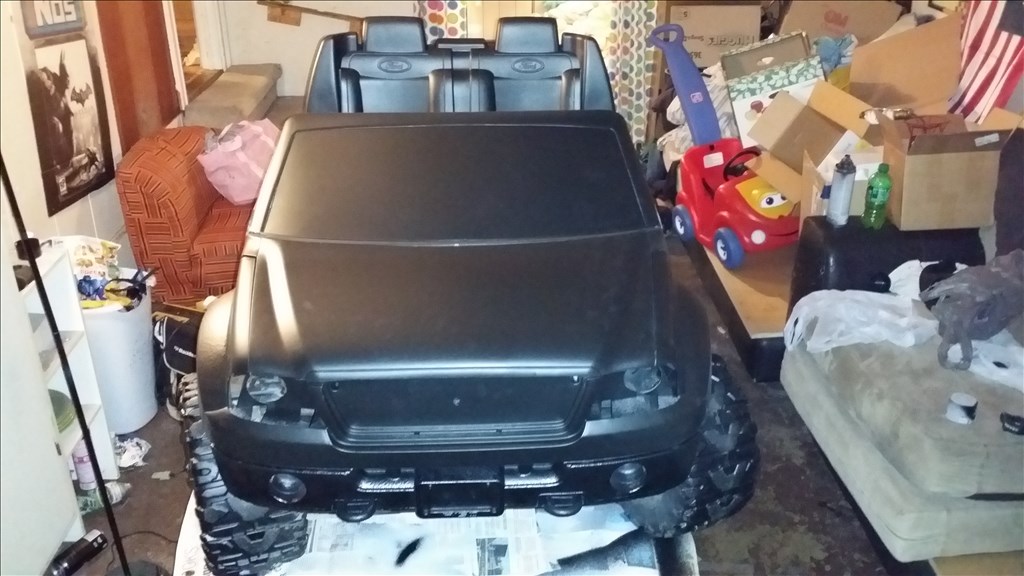
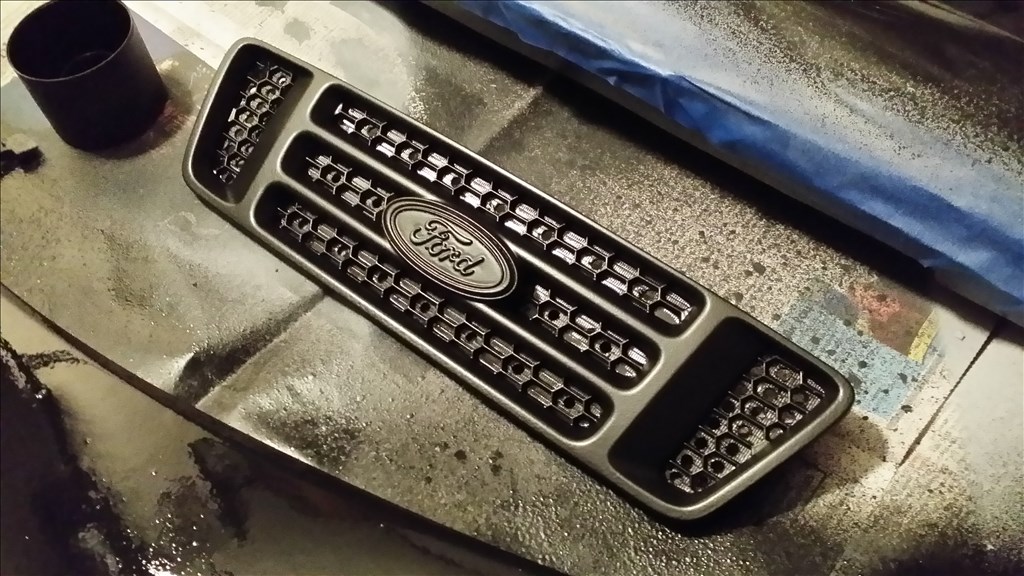
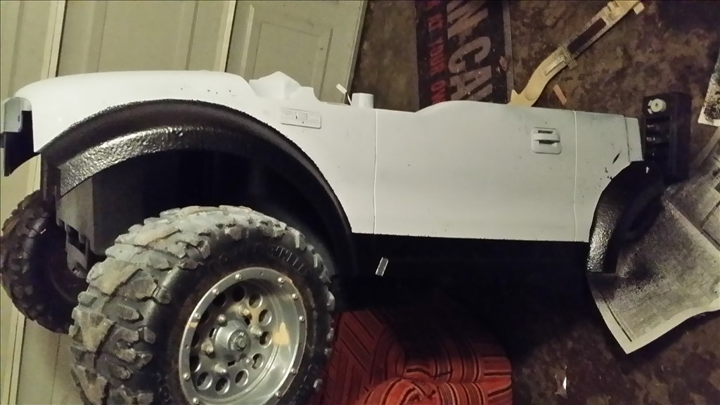
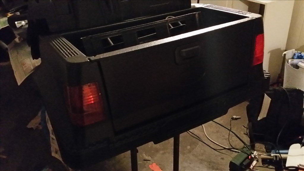
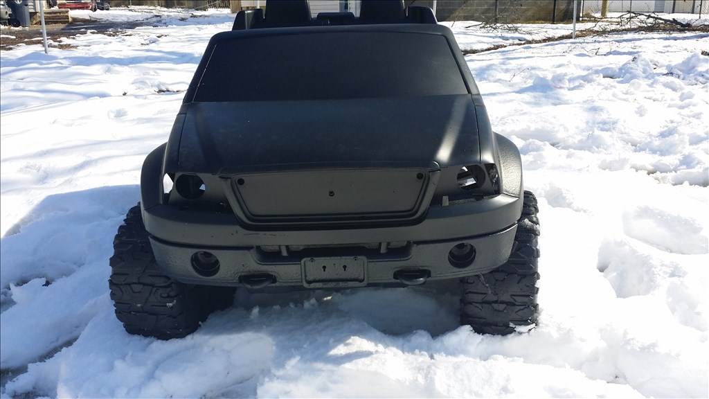
Ok here are some 90 percent assembled pictures. All the screws are not in the body so some things may be out of alignment. Right now I am working to install all the IR leds in the grill.
Ok so there is the stealth black on black paint job and rubber chip guard around the entire bottom edge. I will probably remove the seats but right now they cover two large holes in the floor.
Ok so here's the IR illuminator I promised. This will light up like headlights when a electronic IR sensitive camera is used. I already modified a 2.4 GHz ez cam that I am considering installing dead center of the grill where the Ford logo is.
The 48 850nm IR leds are hot glued in place , now just for wiring parallel to 1.5 volts.
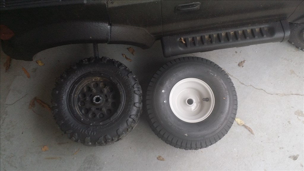
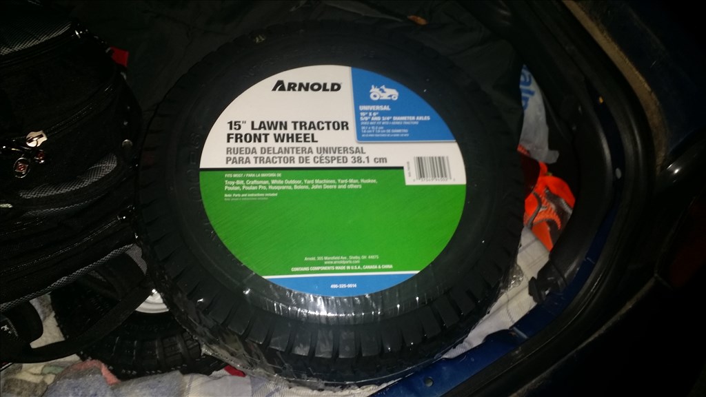
Ok so the last tires I wanted will be too pricey. I must buy a 35 dollar wheel plus 18 dollar tire then shipping for each time 4 wheels. It would have been 224 dollar plus tax and shipping so that's a no go. However I can do a more generic tire and wheel combo for 35 dollars each wheel and they are at home depot locally so there is no shipping.
comparison coming from a 13 inch wheel to 15 inch.
home depot 15 X 6 inch tire on 6 X 6 inch rim
http://m.homedepot.com/p/Arnold-15-in-Universal-Front-Rider-Wheel-for-Lawn-Tractors-490-325-0014/202188267/
$35 each tire.
badass!
https://www.youtube.com/watch?v=VrXNQ_VID4M&feature=youtube_gdata_player
Pardon me looking sleepy , I'm sick and really tired. This kinda gives a explanation of what I'm doing so far.
@Sleenard , Thanks man ! I appreciate it.
Josh those tires will make this look awsome! Great job on the painting as usual.
Once again Josh , very cool project! I have to say you have the most diverse use of EZ-Robot boards! as you have shown, EZ-Robot is easily used as an ez-controller .....good on you! :)
@Thanks Rgordon, I think it would probably handle a great deal better with real tires. Especially since it doesn't have any kind of suspension.
@Irobot58 - thankyou! I try new things and new challenges from time to time. I just need to make more demonstration videos.
What's holding the project up right now is a suitable motor controller. I ordered a 30 amp speed controller yesterday and it's coming by UPS from a USA warehouse.
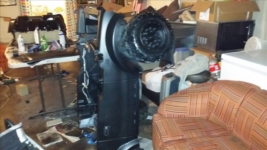
Time to migrate the project from my buddies house to mine. I fit the whole project disassembled into my car.
soon as I have a speed controller ordered I will share it.
I've always been considering similar projects for the EZ-B, every time I see my nephew's ride on bike I want to throw an EZ-B in there and scare him by having it move on it's own.
Better still, I saw this last year, it was soooo tempting!..
Awesome project Josh. I can't believe I haven't commented on this yet. But since I have I'll try to offer some words of wisdom.
If someone wants to do something like this I recommend the garage sale - rummage sale scene. I find lots of cool things really cheap. You can get a power wheels (generic term) for dirt cheap.
@Josh,
The turning radius will be what gives you the most headache. What or how did you say the steering was being accomplished? servo gearbox?
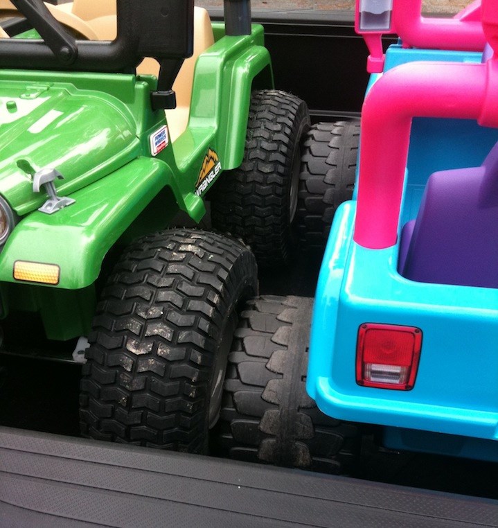
Yea used power wheels are cheap. I bought this one for 40. A friend James decided today he would do something cool with his daughters pink jeep she outgrew , before he gave it a lift he gave it a ride around the yard lol.
I literally LOL at that.
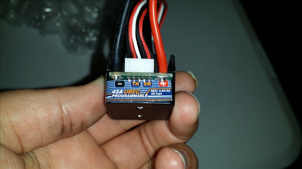
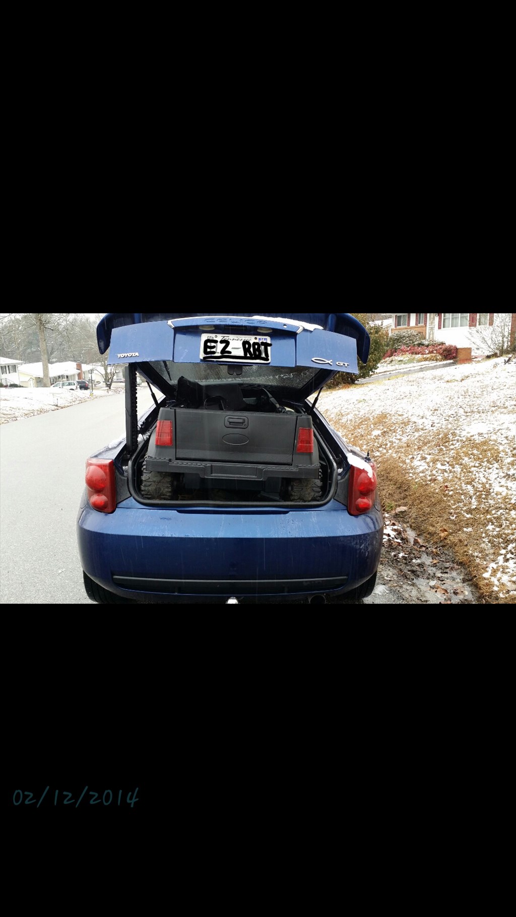
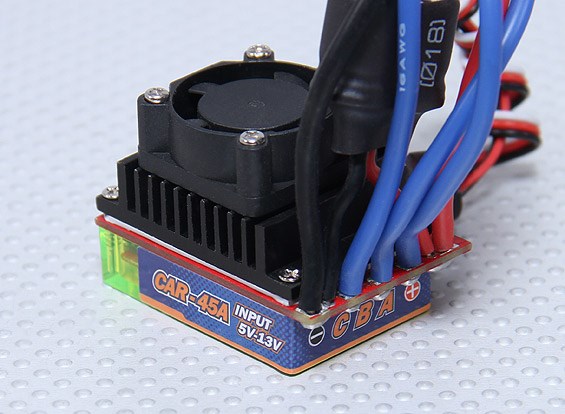
http://www.hobbyking.com/hobbyking/store/uh_viewItem.asp?idProduct=43377
Here is the motor controller I'm using for the two rear brushed motors. I can't imagine they will draw more than 10 amps each at any point so 45 amps should be plenty.
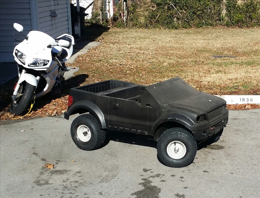
I couldn't resist. We got 6 or 7 inches last night of snow. I was already bringing the truck back to my house.
jstarne1 , I can,t wait to see where this goes. I picked up a pink jeep out for garbage near my inlaws house? Maybe a big RC vehicle or EZB? Steve S
Now that EZB can be controlled by wifi or bluetooth with the android app you can turn about anything into a programmable RC vehicle. Flying quad or hex copter, car, tank, beer robot or whatever you can dream up. Ezb can do what hundreds or even thousands in specialty marketed hobby items would do for you. :)
So far I'm waiting on the speed Controller to have forward and reverse so i may not have much progress this weekend. Also I'm waiting on the led headlights and tail lights I ordered this week.
A few items on the agenda.
Lights arrived...
A single bulb lighting up the corner of my kitchen , they are fairly bright so imaging 4 of them now I just need the speed controller to start wiring and testing this bad boy
Hey, I have a brushguard bumper of a jeep pwr wheels that would look great on the front of that rig. Do you want it? I can get a little bigger box and add it to your care package.
Sure man if you want to send it i can see if it will fit on. You know me I love custom stuff.
Great news the Hobby King 45 amp Brushed motor controller came in.
i will need to change the connectors to my favorite Turnigy XT 60 connectors because this isn't going into a little traxxas branded car. It's going in a Giant sized RC power wheels truck. :)
so how are you going to do the steering set up. i have a similar project I'm doing but I'm sure there's an easier set up then the way im trying to make work. I'll post some pics of mine
Hi snake , I'm just going to use a single hi torque servo and servo city gearbox for steering. Project is on hold till the v4 is caught up on shipping.
Okay Josh, my granddaughter is finally here and my baby woodworking projects are finally done, so I can finally concentrate on robots. I will send your care package. I'm sorry I've taken so long.
That's awesome Brett , i look forward to it. Thankyou
Hey Josh, I have a hotwheels pink jeep grandkids don,t like. Does not have high speed like others. Do you have a link on the HobbyKing 45 Amp controller? Post #47 I can not find with HobbyKing search. Like all our upgrades. Thank You, Steve S
@ Steve , here is the link http://www.hobbyking.com/mobile/viewproduct.asp?idproduct=13445
the brushed 45 amp car esc with reverse.
Josh, Thanks for the link. Have you had any chance to try it on your awesome Power Wheels build? It said you have to set it up for your throttle. I like all the details on your truck. My grandkids drive the crap out of the 2 free ones that I got, only had to buy new batteries. Your idea of two 6 volts might give more run time than the stock 12 volt. Thanks, Steve S
Hey Steve , i got the v4 boards this weeks but ive been super busy between work and school. I want to get the truck operating soon , basically it needs the wiring , mounting a steering servo and the speed controller and it will be scooting around the yard lol.
HELLO COMMUNITY, I just needed to survive midterm for this semester going back to college and now I am moving forward with projects. I left off this project at the lighting in case it gets dark and local authorities have issues with a motorized vehicle without lighting. Plus it looks cool! I did some tests and found that the plastic tires on the power wheels are slick and hard. This results in poor traction on both grass and pavement. Realistically I needed to replace the wheels to make this platform usable. I also have plans to swap the mabuchi motors over to Traxxas Titan 775 motors with a heat sink. These motors are roughly 1.5 horsepower max mashed on 1 hp being 745.69 watts. I may edit this post a couple times as I add in my immediate plans for the next few days of work on the project.
Hey Josh, That's great you are resuming work on this cool Power Wheels project. As you are probably aware, that are many possible wheel upgrades listed on the net. Some are simply cutting bike tires to go around the plastic tire and screwing them into the plastic. Other options are cutting the tread area off of old golf cart tires and slipping them over the plastic or just replacing the entire wheel, like you mentioned. Some people have had better luck going to 18 volts instead of 24 volts. They mentioned with increased power they realize more steering drift or push. It is wild what people do with Power wheels! I will be following your post. Thanks, Steve S
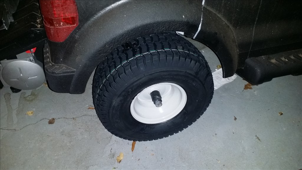
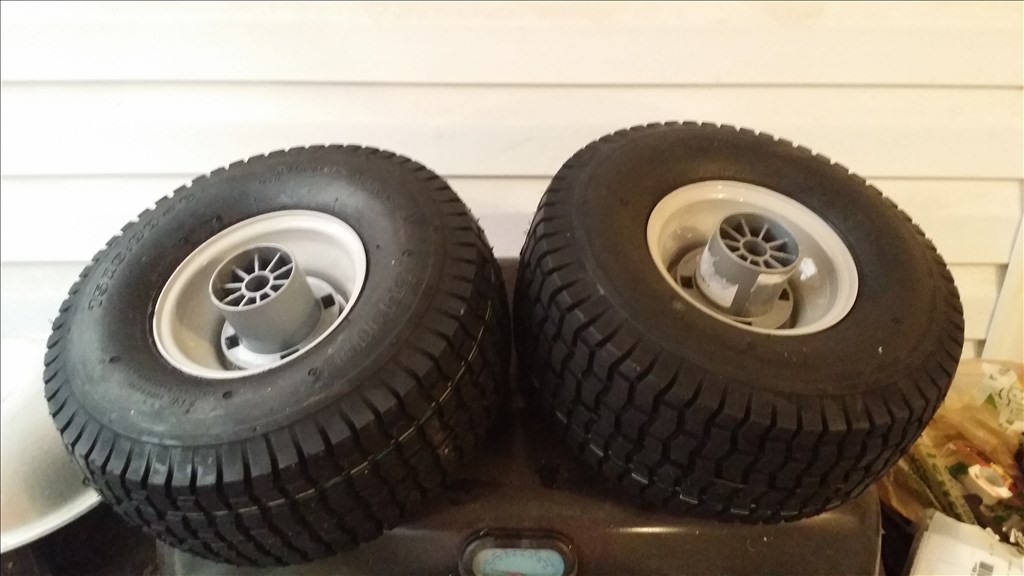
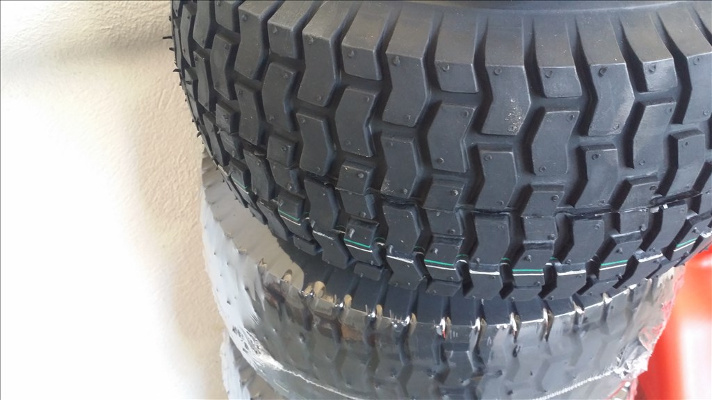
I may just stay with 12 volts. It will be easier to power and wouldn't be a strange battery configuration. 12 volt can be charged by an inverter or a 12 v car battery charger. That being said I did do some shopping and found perfect tires. Match the size and width of the original and they come with different options for bearings. I will be using a grease bearing insert. Check out the pics.
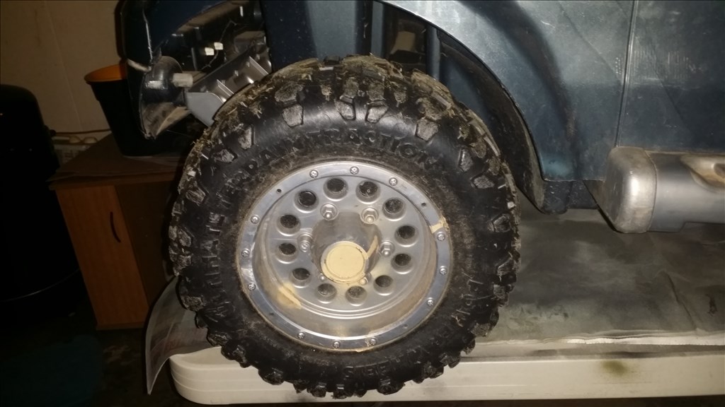
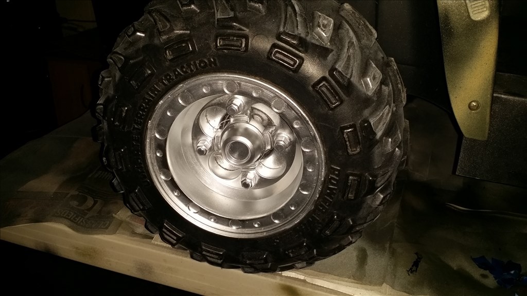
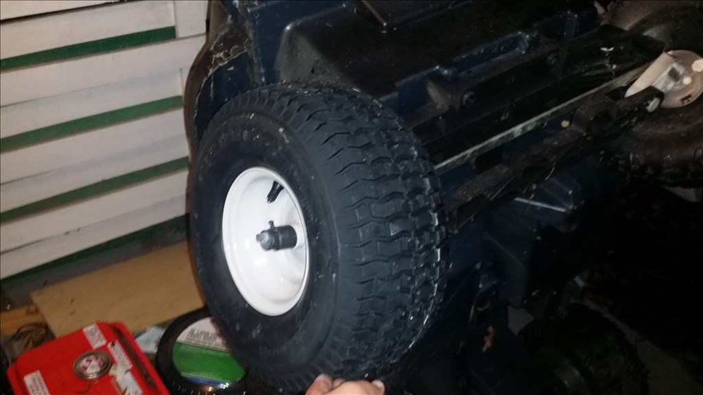
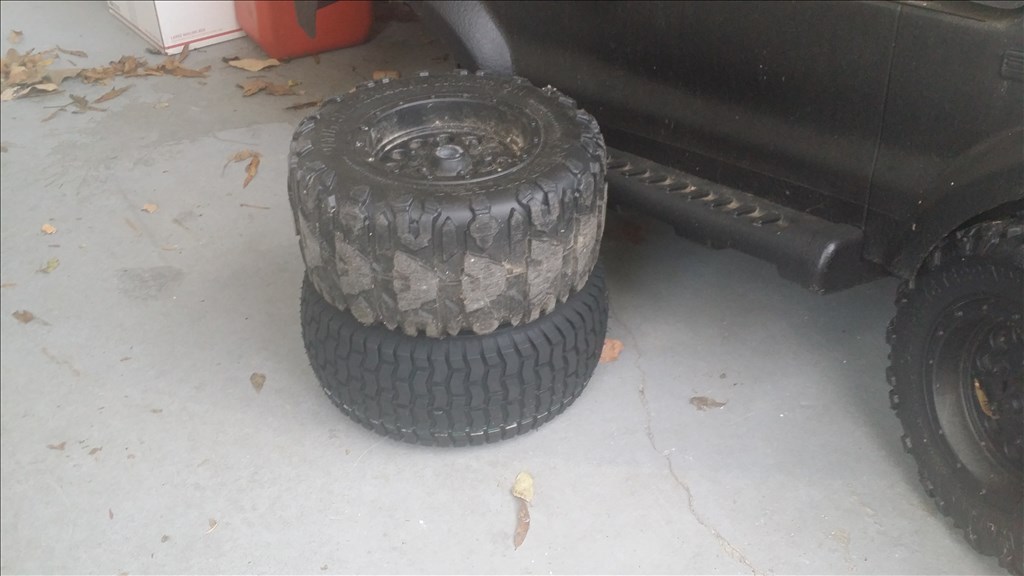
Ok here is the exciting part , the comparison. .... drum roll please...
Oh yea! That is golden! Other than the center strip bulge in the tire it is dead on the same diameter and thickness.
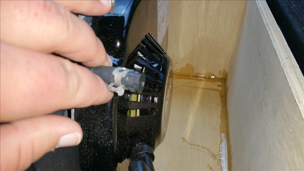
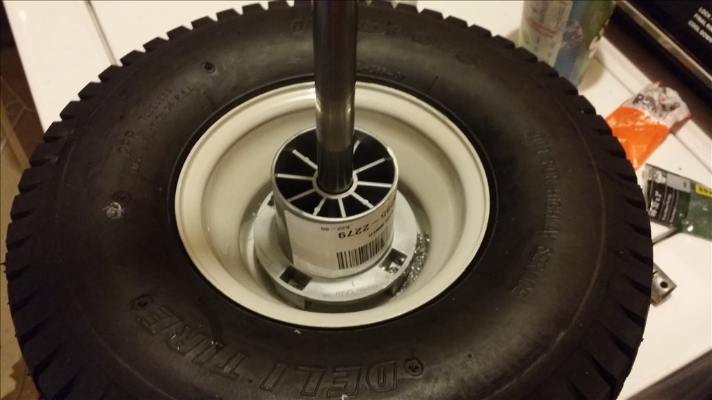
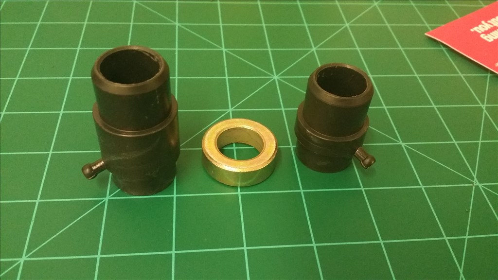
Ok so I am trimming the bearings because they are a tiny bit tight to easily slide on the shaft. The bearings are 3 piece teflon. The brass ring is a spacer that can be used on either side needed. There is a nipple on the bearing to inject grease for lubrication.
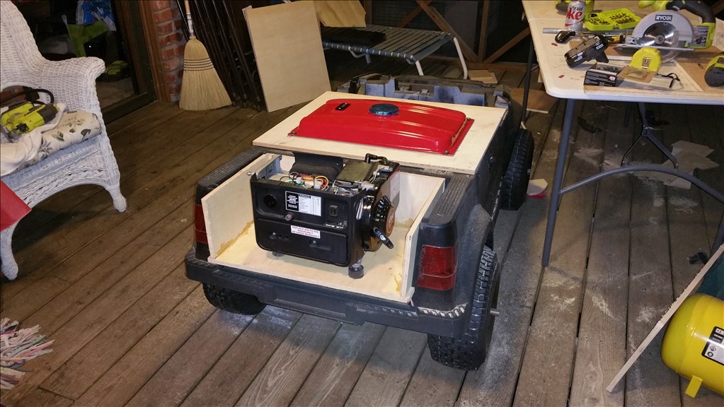
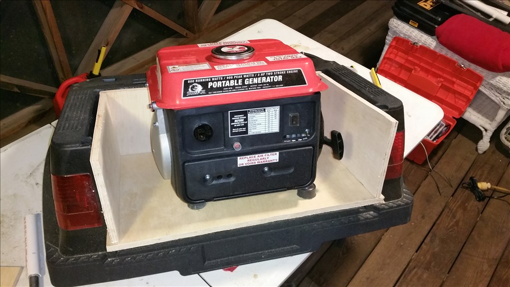
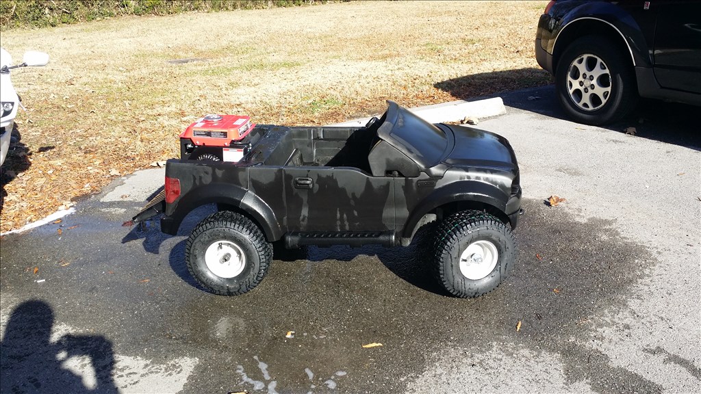
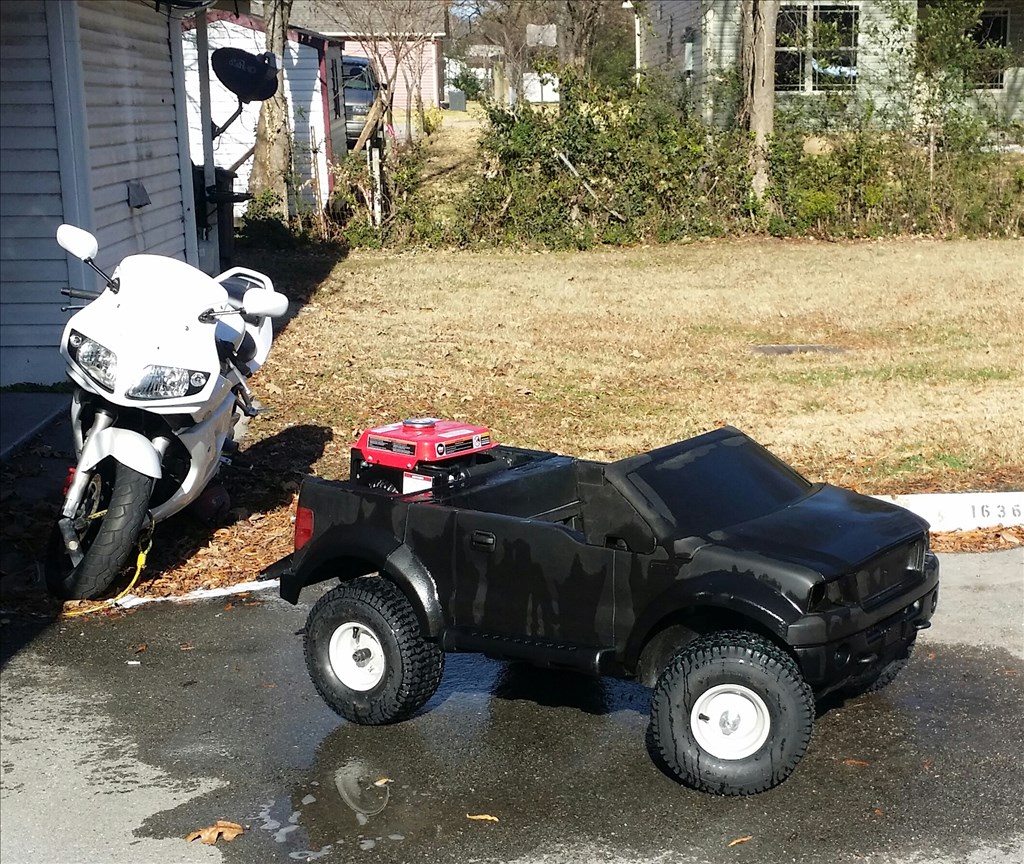
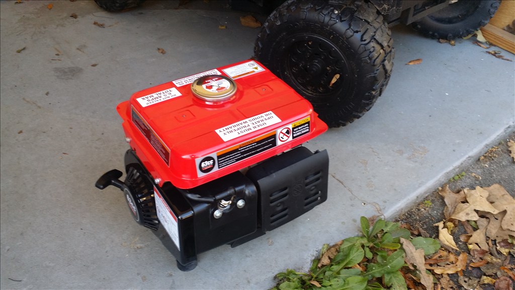
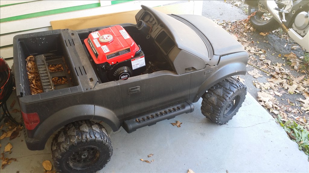
While thinking of how I will actually use the platform, I looked at some practical aspects. I like to go camping, but I cannot take much with me because of weight. If I had a mule to carry stuff and follow me as I hike how cool would that be right? Then I considered that batteries simply won't cut it for extended use. That being said I also do not want to change the whole system. So a potential compromise is a small generator that keeps the 12 volt batteries charged while in extended operation. Then once I arrive at the camp site even when the robot is not in use the generator is useful for charging cameras, ipads, phones or even power a grill or small heater if you really get into bad weather. That being said there are some generators that are 49 cc but I went with this 630 storm cat for 139.99. It claims to be able to run 400 watts ( half load) for 5 or more hours. Imagine the hiking range if you had a small 5 gallon jug with you? This generally speaking is efficient because using a actual 2 horsepower gas motor to drive the wheels could not go 5 hours without a fill up with consistent use. I will swap the gears and motors with all metal ones to eliminate the possibility of stripping.

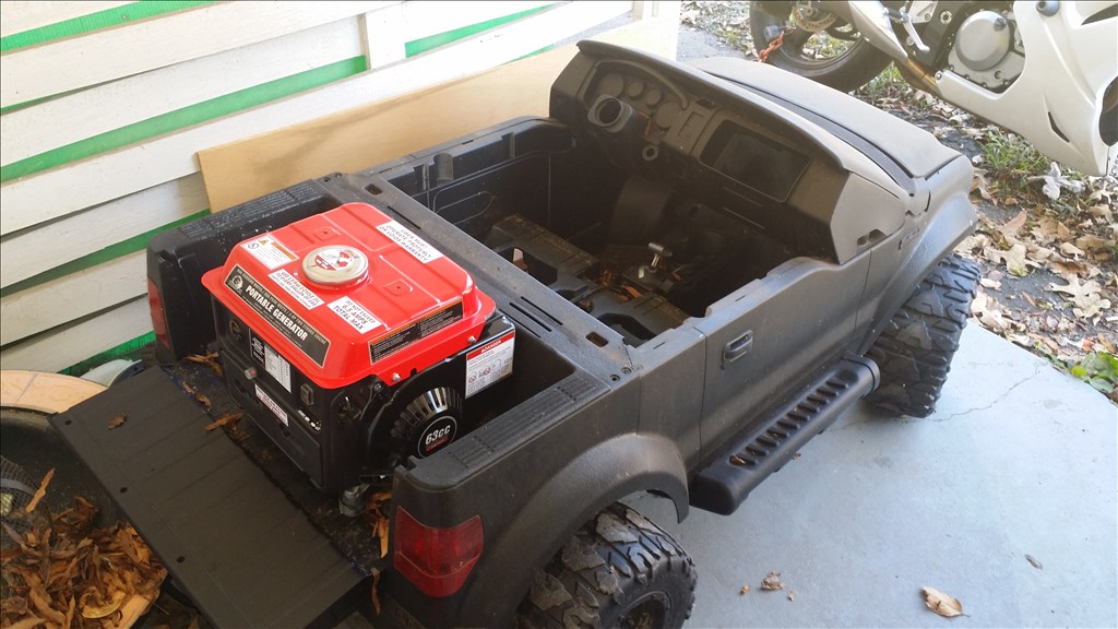
agian the generator is portable so I would just drop it in and plug in 12 v charger/ power supply. No modifications would be needed to the generator and could be unplugged and removed once I reach a destination. Batteries only provide 20 to 40 min run time by themselves using two Power Sonic SLA 12 v 9 ah batteries. I have not decided if I want the 35 pounds of the generator in the back or the center.
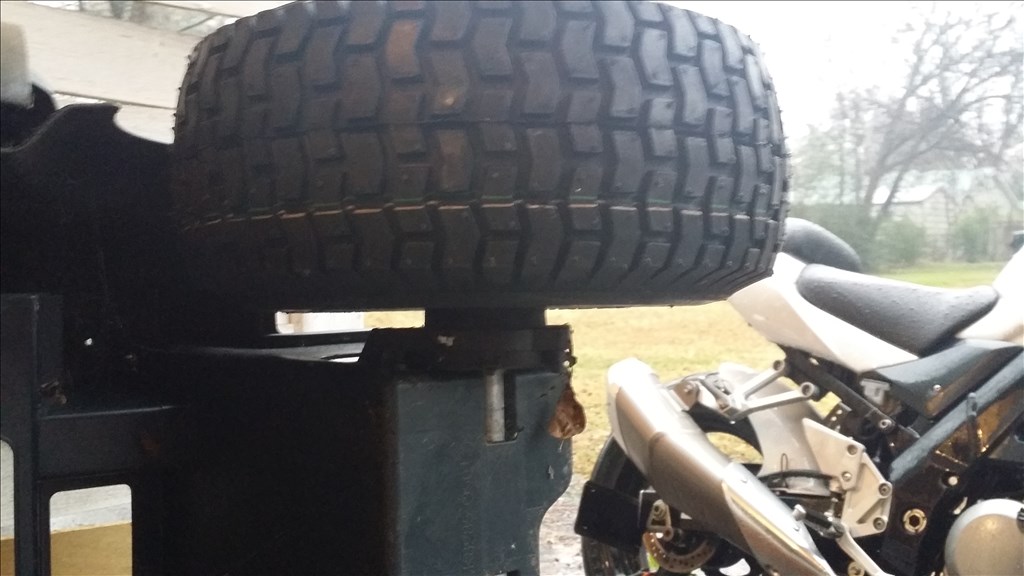
I am leaning towards the motor being in the back , it looks at home there right?Any suggestions?
Hi Josh,
Glad to see you getting back to this one. I have always wanted to do this kind of robot. Kind of a yard patrol bot with water cannon or paint ball gun.....
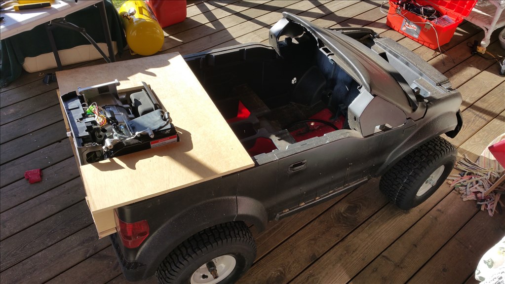
I think your generator (great idea BTW) would be better in the back to help with traction.
Rex
If this becomes a longer term project I have considered modifying the generator to have a electric starter instead of pull start so the robot can kick the generator on when the batteries are getting low. Thank you for the rear position suggestion , I think that is the best as well !
Josh,
I was showing my assistant and she wants one. Are you going to modify them and sell?
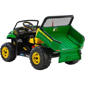
The utility concept I am proposing could be useful for anyone who goes outdoors. I am not opposed to building one for someone. Are they wanting one for a kid to still be able to ride, or instead a robot mule like we were just discussing? I can do whatever she wants. The best power wheels model, as a donor, is the Peg Perego John Deere Gator 348.99, which is my logical upgrade once I get the kinks worked out of everything. This is because there is more physical room on the gator and the bed can be removed and seats removed and a flat bed attached for more load space on top. Just let me know what she wants.
Or if she wants to stay with a Ford f150
Ok so I wanted to go over the general costs so far for this project in the event someone wants to duplicate it.
F150 power wheels (used $40) $349.99
Power HD 1501mg servo ( steering) $25.00
Servo City metal Gearbox 5:1 $ 80
4 Arnold 15" x 6.00 turf saver tires and wheels. $ 35 each x 4
EZB V4 99.99
Foscam pan and tilt $70
Ezb Camera $50
Hobby King speed controller $30
6 led lights for lighting $20
800 watt storm cat generator $129.99
Nice!
Thanks Bret!
Power system inspired by the Chevy Volt?
After you said that I felt the need to read more about the Chevy Volt , http://en.m.wikipedia.org/wiki/Chevrolet_Volt
It looks like the Chevy volt has a planetary gearbox and clutch. It physically drives the car when the batteries die. So I can see my version has some similarities, but more simplistic. :)
Back to the generator position, put the weight over the drive wheels to help traction, this is what a lot of car manufacturers do (however more of them don't).
Mid positioned rear wheel drive cars such as the Toyota MR2 (AW11 & SW20), Lotus Europa, Esprit, Elise, Exige, Evora, McLaren F1, MP4, Pagani Zonda etc. etc. etc. have amazing traction because the engine is pretty much directly above the drive wheels. It's also means it's more efficient, improves acceleration, etc.
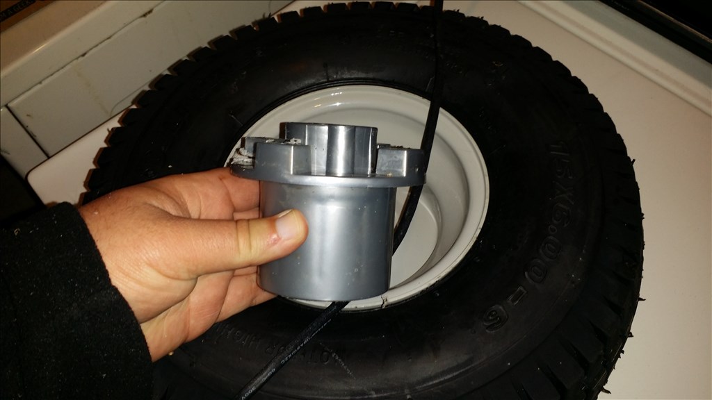
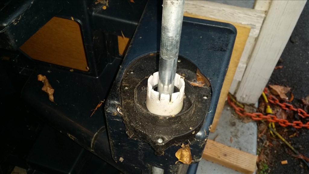
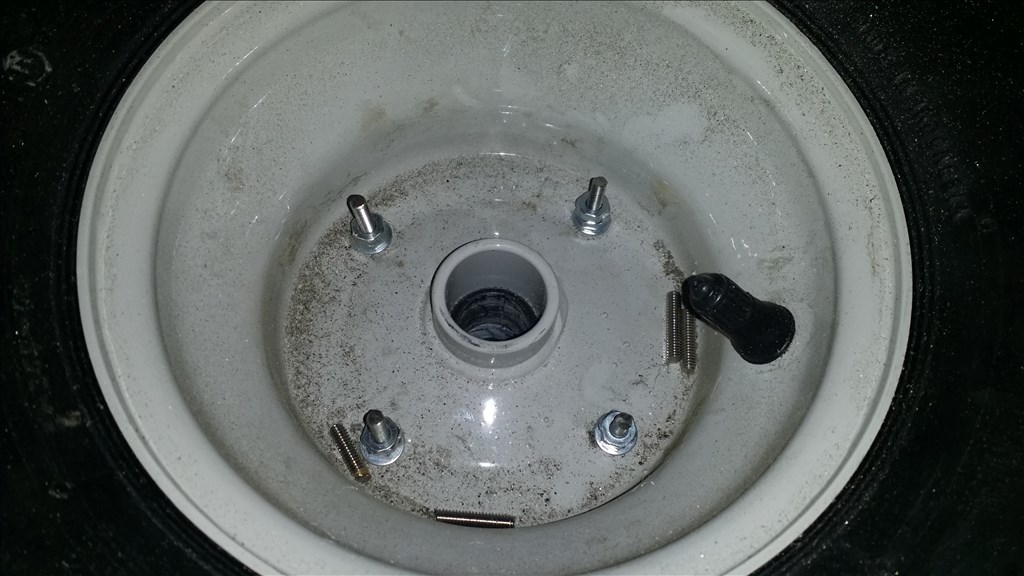
Ok so rear position for the generator is unanimous. I needed to hit the bearing with a Dremel as the edges were to narrow to slide onto the axle. Here is a picture. The next step is to mount in some way the drive hub. I want to bolt it in but I'm concerned I may cause a air leak in doing so.
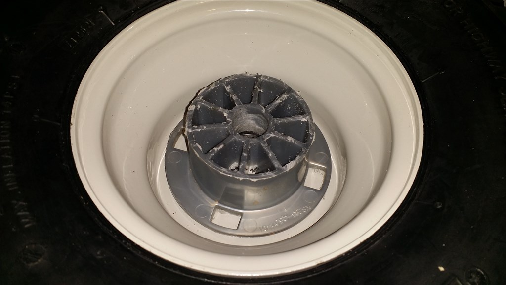
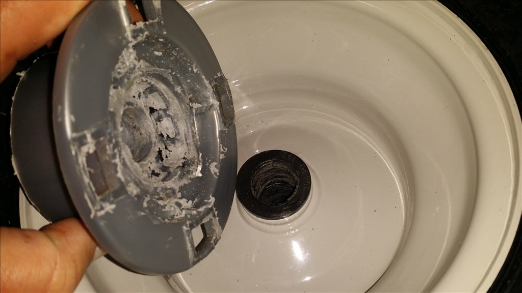
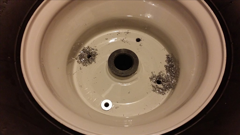
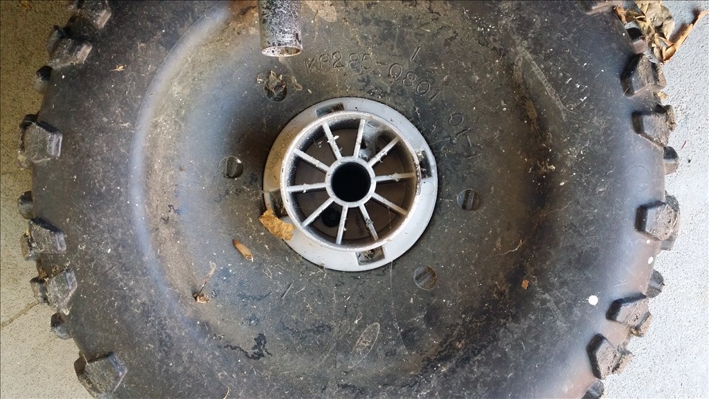
Ok so I have been cutting on the "drive hub that was screwed to the original hard plastic wheels. I made progress to get the hub to fit against the wheel but also accidentally cut too much off the end and now the tire rubs... oops. Well that sucks. I have two options. Either find a replacement online and redo the cut or try drawing this whole part on 123d design and 3d print it. 3D printed PLA is probably not near the strength of heat injected ABS plastic. Here are pics..
Here is the tire in ideal position and you see the gap that I must fit the drive hub into.
Ok so I have been working to see what I can do to get the front tires on. The front axles are about half of the size. I have two options.
The steering is limited by stopper nubs of both sides of the steering link. I cut these out to see what kind of additional range I would get without them.
Ok so as previously noted I cut the hub about a inch too short because the shaft slid. I found cheap replacement hubs for less than 4 dollars each and that negates the time it would take to model them in 3d and print on the Makerbot as I would need to print with zero infill for strength.
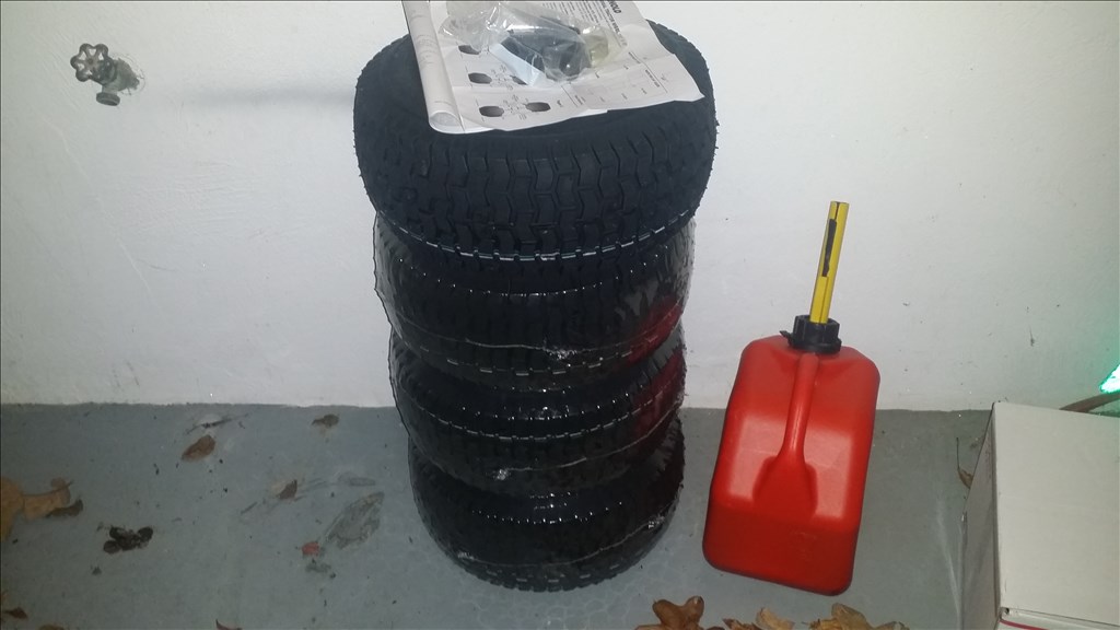
I purchased 4 total just in case they are needed for some reason. The price was too cheap not to.
Nice recovery!
Ok so I really want this project mobile within a couple weeks before colder weather with Ice and snow arrives. It doesn't need to be finished , but I still want it moving. I looked at other steering arrangements which varied from windshield wiper motors to 300 dollar 100 pound linear actuators. In either case I opted for a cheaper option that also allows me to upgrade later to a stronger servo or add an additional gearbox in tandem which is common in RC Monster trucks for off road / rock crawling.
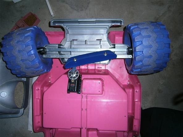
Here is one "ok" diy install of the servo gearbox and a typical 10kg servo on a barbie jeep.
And another example
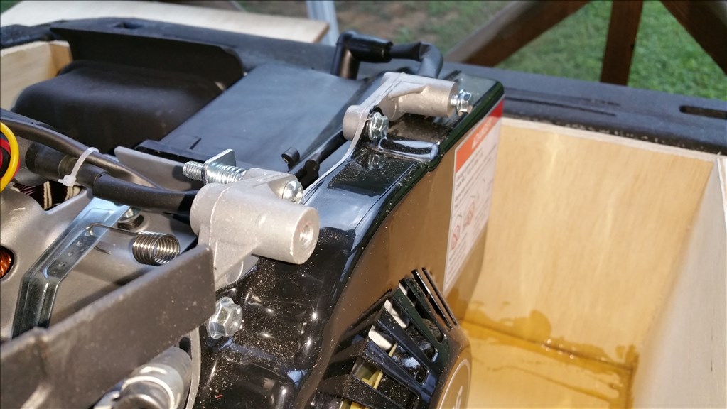
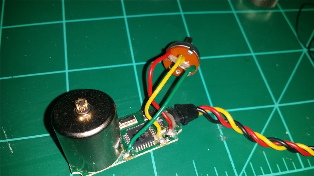
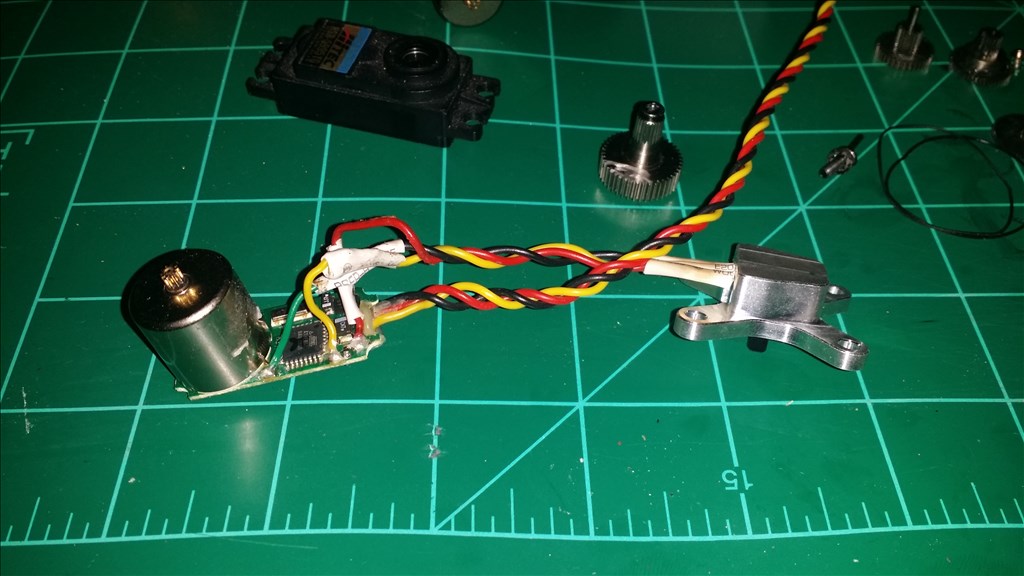
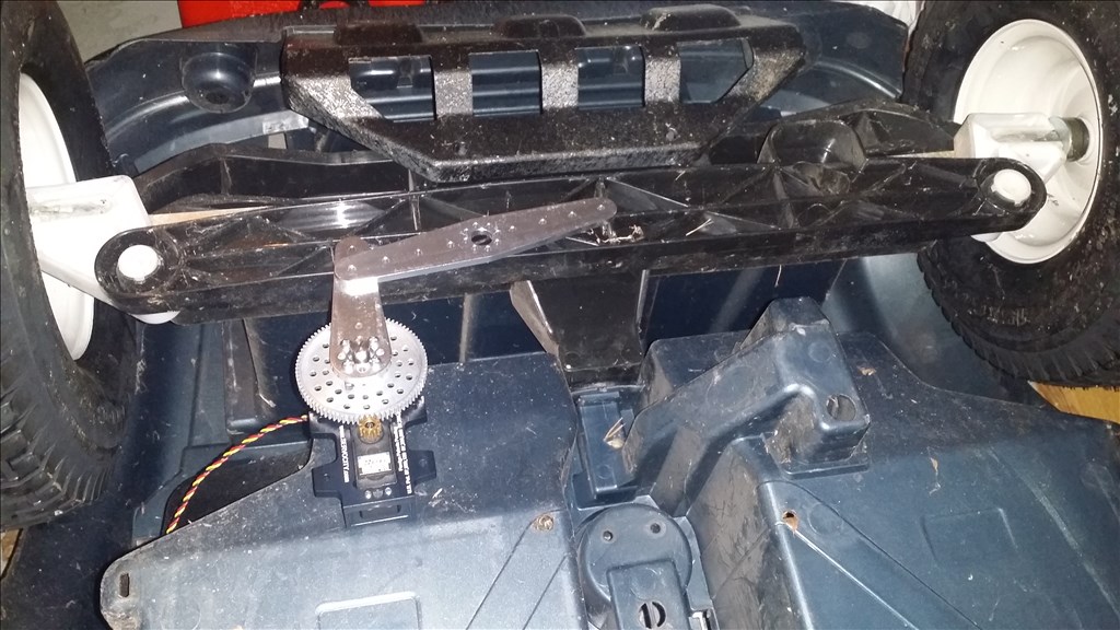
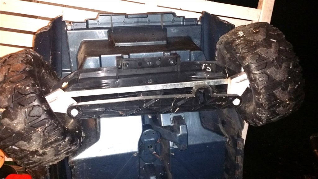
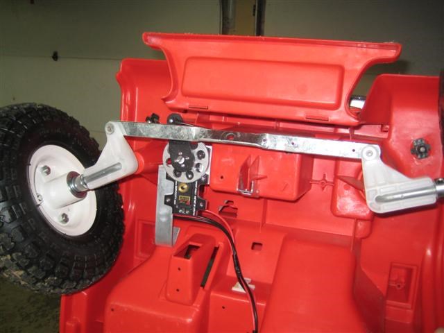
Here is my current power wheels f150 steering system. The metal bar is just for stability, but the large back bar is the "moving" part.
I have the servo city 400 servo gear box with surface mount tabs and a 7 to 1 gear ratio.
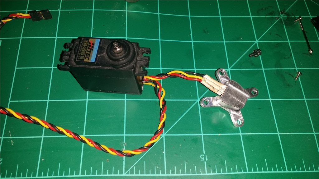
I have two servo options from what I have in my toolbox. Power HD 1501mg , 240 Oz. in. @ 6v
7 x 240= 1680 Oz in. /3 in servo horn =560 Oz in
Hitec 5595tg 333 Oz. in. @ 6v
7 x 333 =2,331 Oz. in.
2331 /3 in servo horn= 777 Oz in
It is possible for the torque to be higher on higher voltage ( 7.4), but I also need to keep the servo cool.
A 7 to 1 gear ratio also slows servo response from .16 to 60 degree 7 times slower. So with the gearbox it would be 1.12 seconds per 60 degrees rotation. That's about 2.26 seconds from lock left to lock right. So I believe it will be usable. In the worse case scenario I would swap to a 5 to 1 ratio and tandem the connection for two servos to move together.
For now I'm using the servo city 400 servo gearbox with a 7 to 1 ratio in my B9's robot arm and it's pretty slow. Less than normal human speed. I also am thinking about dropping to 5 to 1 but I may need the torque. We'll see soon. I'm not sure you'll be happy with the speed of the 7 to 1 when used for steering. I'm looking forward to seeing how it performs for you.
There may be trial and error , if needed I can swap to 5 to 1 and put two in tandem. I took a look at the steering and it appears that 4 inch travel is the movement lock to lock, left to right. I do hope and cross my fingers that this is plenty to make the steering movements. The only other option I can think of is a linear actuator with modifications to act like a servo but that runs 300 dollars for a 100 pound actuator.
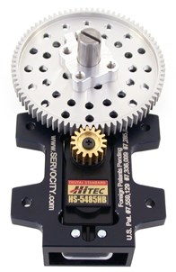
SPG785A ServoCity.com Top Mount servo Gearbox: http://youtu.be/2aYheb8mFC8
Here is the gearbox demonstration from servo city. My servo is a tiny bit faster than this one and digital. The full range of movement should be between 100 and 120 degrees of servo rotation.
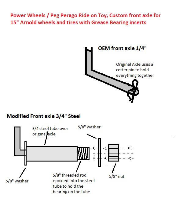
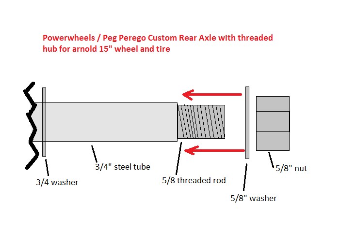
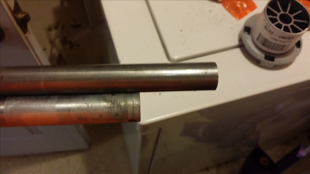
I dropped by home depot and got lucky. I found stainless steel polished tube that slides right into my grease bearing sleeve. I believe it even may be long enough to replace the original aluminum rear axle as well so that the suspension will flex much less under weight.
The stainless tube costs 9 dollars and some change. So if I need a second one I won't break the bank.
I checked the length on the steel tube and it's a tiny bit longer than the original. This gives me the option to make the wheelbase a couple inches wider as well. This is another happy surprise !
So I need to solve two problems.
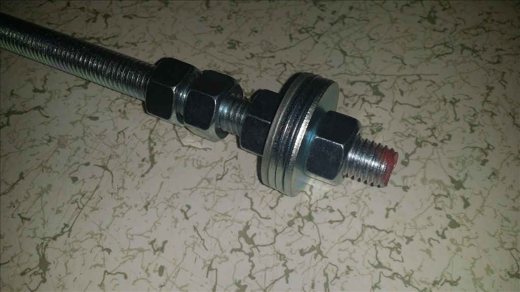
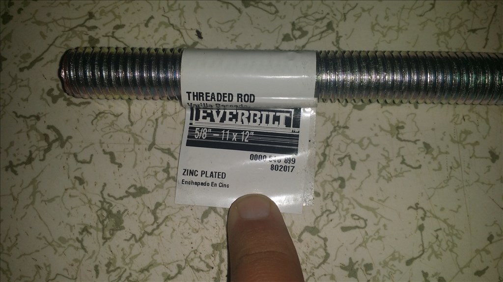
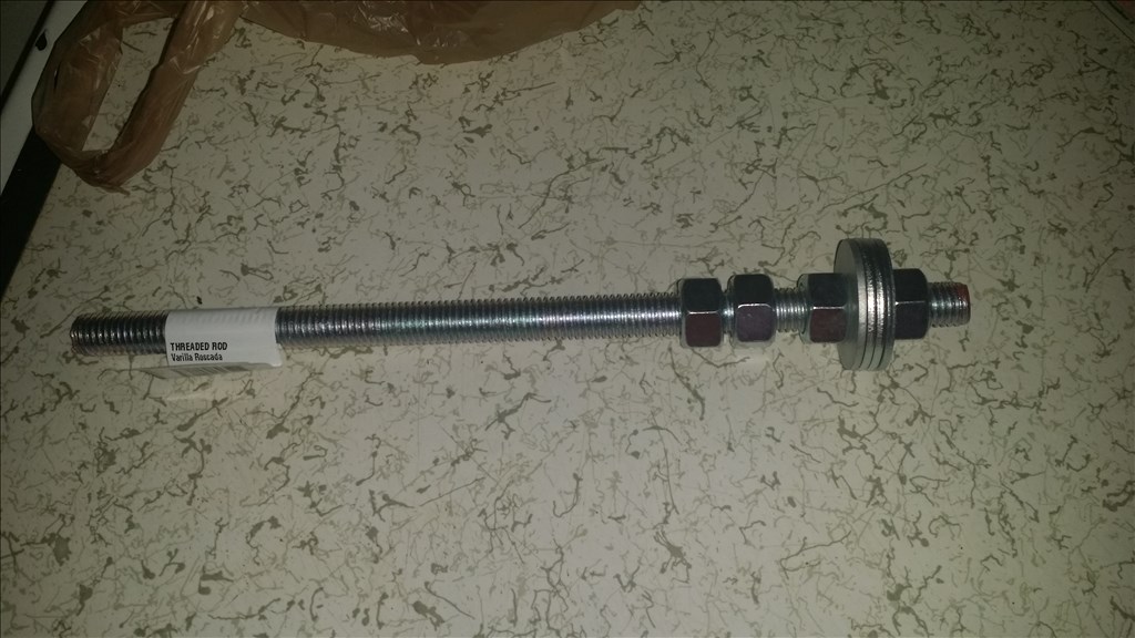
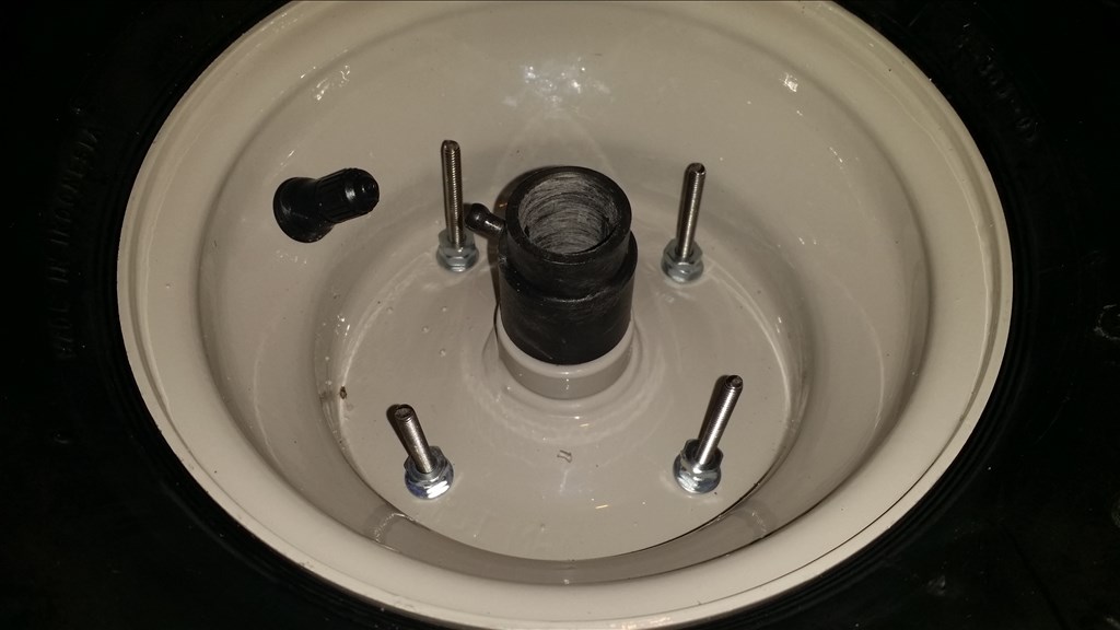
Ok, so I picked up the zinc coated threaded rod , nuts and washers. It is 12 inches in length so I will cut it into 4 equal sections, 3 inches long each.
Wow you are making some progress.
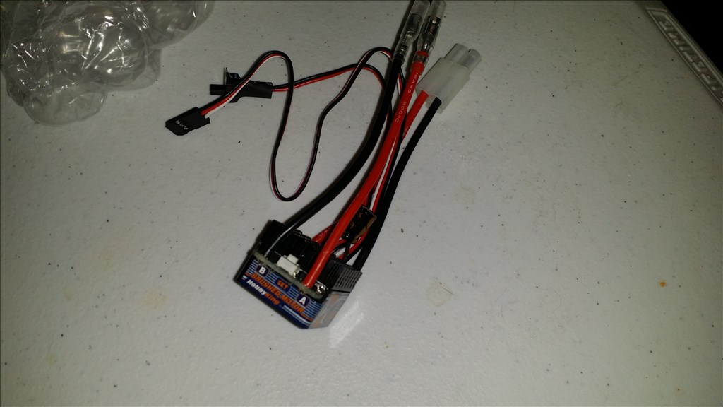
Thankyou Sfoy , I would really like for this guy to be able to move. I am looking for my brushed motor controller and I checked the specs and now the specs say that the controller is good for a certain sized lipo. I will post the specs.
Edit: ok so I don't like the setup of the rc motor controller , they are loud and make crazy beeping noises everytime they turn on before they arm. So I am considering a completely different option. Either a relay or a H bridge serial controller from dimension engineering.
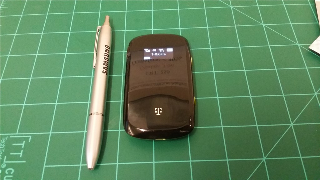
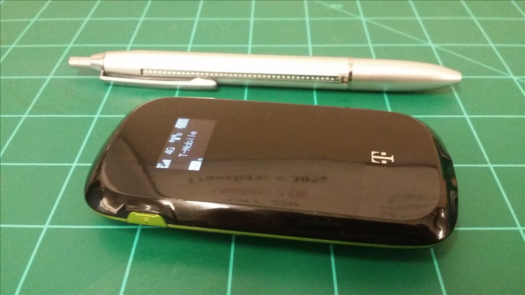
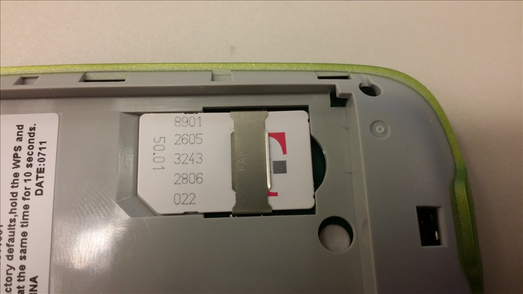
Shifting away from the H bridge , I received today the portable USB power router I purchased for 15 dollars. It is an older model from 2 or 3 years ago. That would be the first generation of 4G but not LTE. It connects to a cell tower for 4G internet, but also can interconnect 5 devices through WiFi. I'm going to test it out. Basically I could have the tablet run the robot but I could remote desktop from a longer distance without fear of being too far away. The obvious backup of course would be I just needed to get closer to the robot but I eventually want to go for some autonomy, but still be able to monitor everything from a distance. So anyways I did latency pings and speed tests with Ookla.
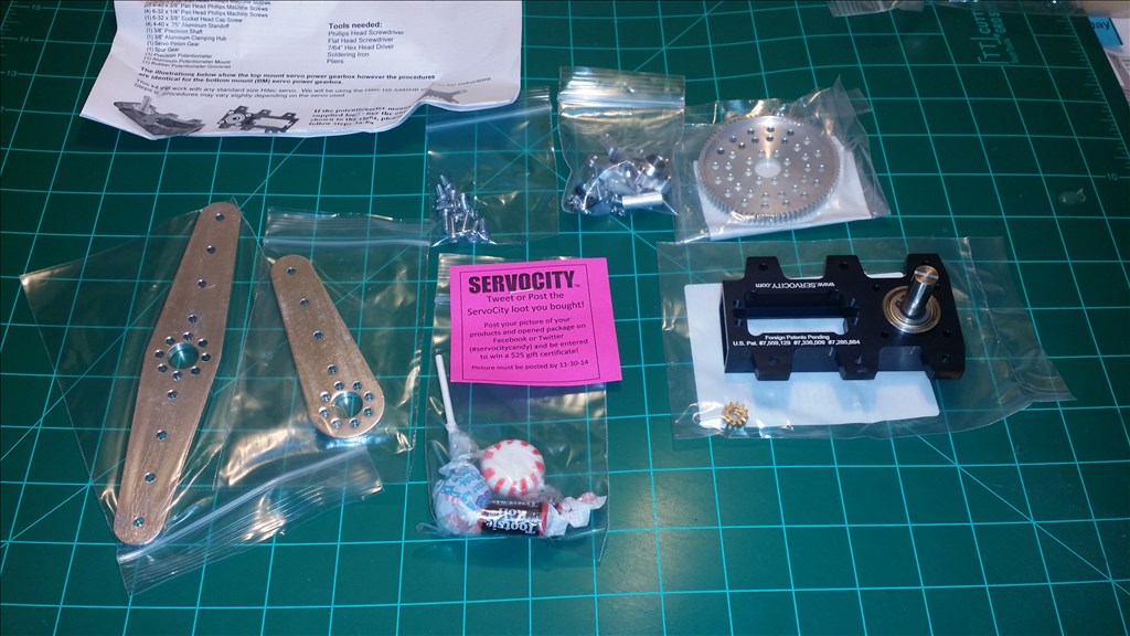
Great news , the servo city gearbox arrived for the steering on this project. It is a 7:1 ratio of the donor servos torque. All the parts a machined aluminum and very strong for their weight. I love that they put candy and mints in every order. Usually they do a hand written note as well. #servocitycandy
ServoCity Rocks! I just placed a $100 + order with them.
Do you submit picks and links to your project with them? Each time you mention them in a forum like this and give them a link to check they'll give you 10 - 15% discount on your next order!
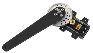
I love the looks of those aluminum power gearbox arms! They look very strong.
I did try to bend the aluminum servo arms with my hands as soon as I pulled them out of the box and they are really stiff! They are no joke. They are physically thicker than they appear on the website. I did tag them on Facebook, but I will need to see about this percent off thing as I have a handful of their stuff and I love their products. No one else is making the things they machine. I love it!
They're stuff is the key parts of my B9 arms. Very strong, light and amazing. It's amazing how interchangeable their stuff is.
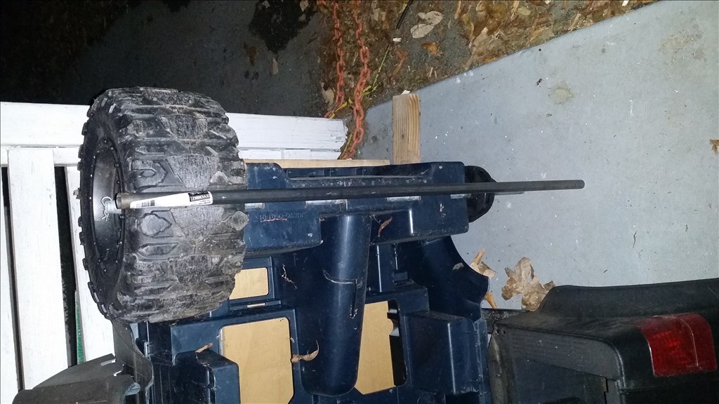
Alright , more parts arrived. This is to undo my epic screw up when I cut the last hub about a inch short. Here are the replacement parts and extras. The rod is the steering column that originally bolted to the steering wheel.
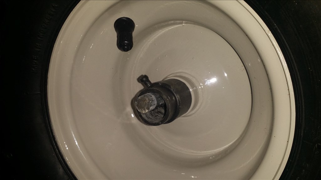
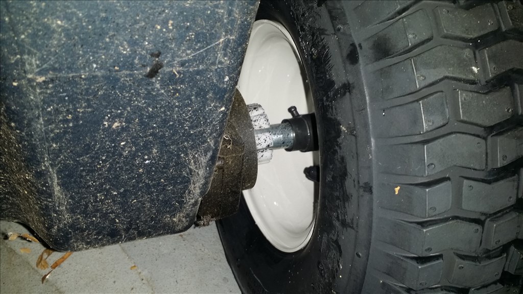
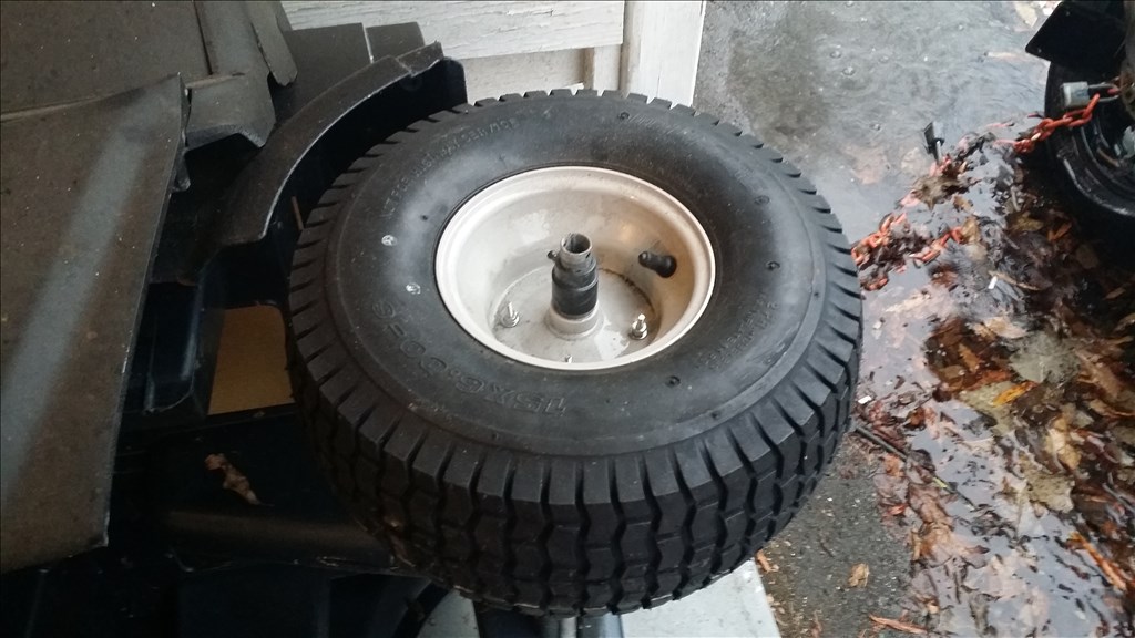
Ok so I put the bearings in the wheels and slid in the new axle. Perfect fit. Then slide the power wheels gearbox coupler hub on as well. I did this to ensure that the hub was centered when I drilled the holes and billed everything together. It wasn't perfect because I don't have a drill press but a hand drill did the job.
Ok, so now I have two sets of bearings and two tires ready to mate with the original power wheels gearboxes. There is both a right and left one.
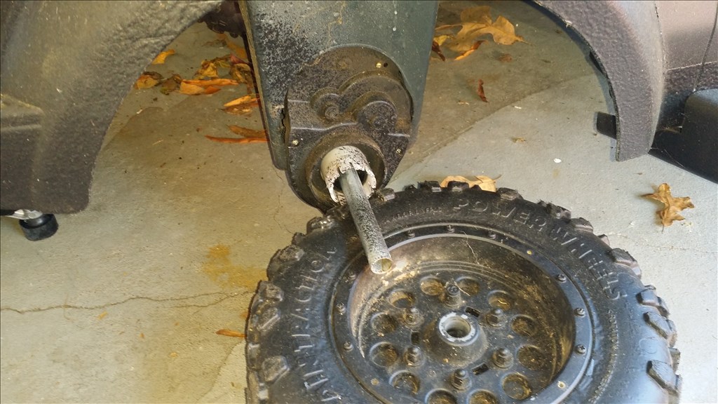
The original shaft is corroded and no longer smooth like the new shaft. The wheels spins freely on the new one but the old one has a great deal of resistance. I may consider not cutting the shaft down until everything else is done so I have wiggle room for any errors. Next I am moving to the front wheels and axles. I hope to have all 4 wheels on the truck today now that I have the hardware.
I do have a couple problems. First the left front tire axle is too long so I need to trim it back some. The front wheels wheelbase is a tiny bit wider than the rear so I need some adjustments. The front wheels alignment is a little off, but I believe it came that way. I may need to hack saw the steering link then fiberglass it back together about a 1/2" wider to fix the alignment.
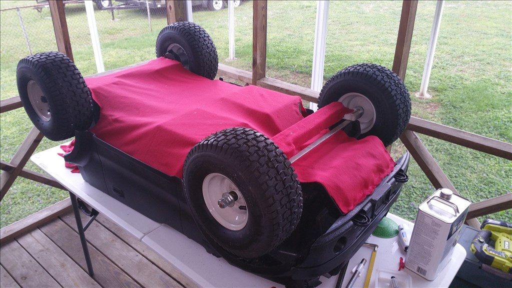
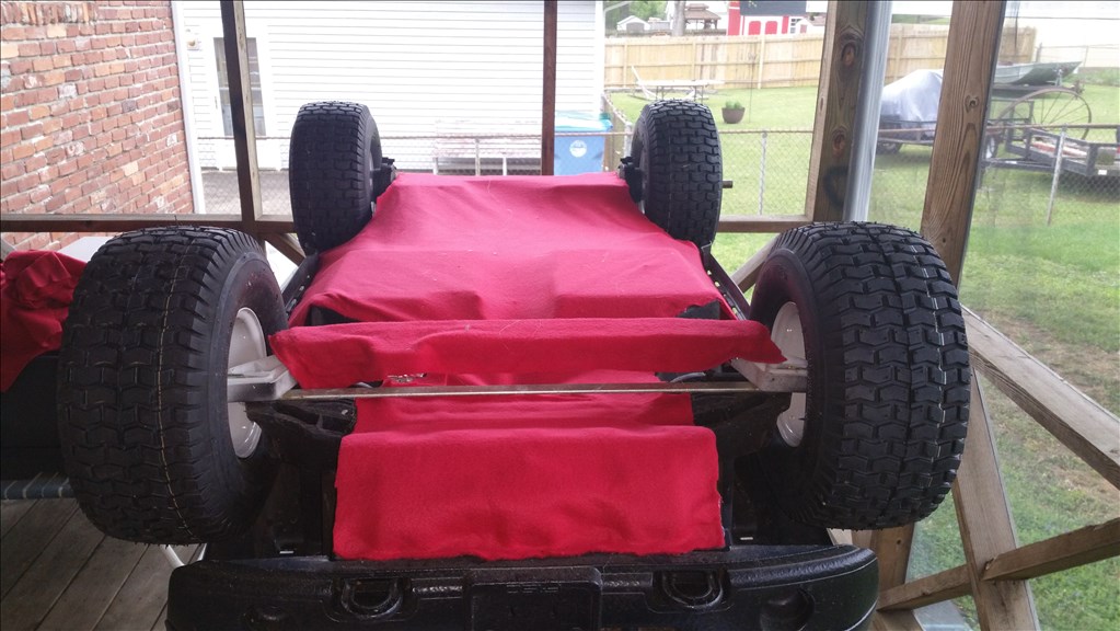
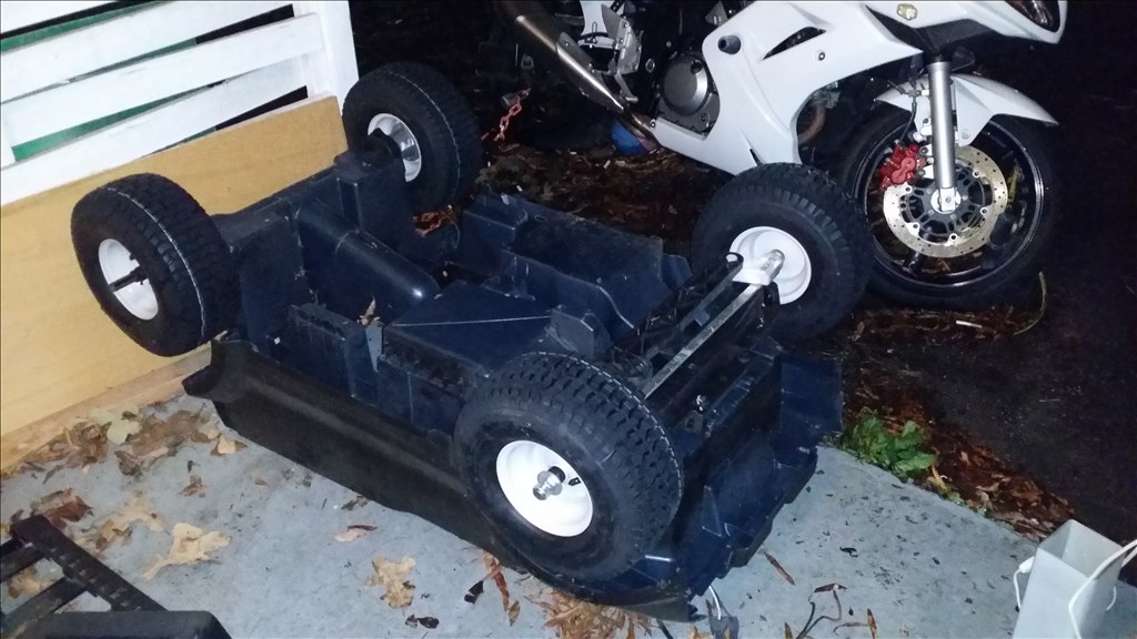
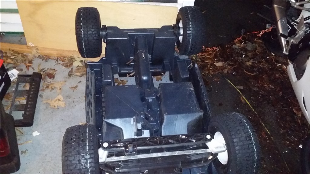
I'm letting it sit upside down while the epoxy fully hardens holding the adapters to the original front axles. Tommorow I will take a picture of it the ride side up. :)
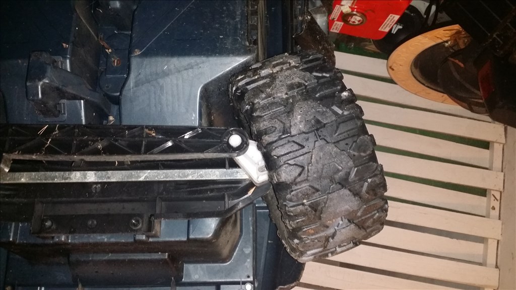
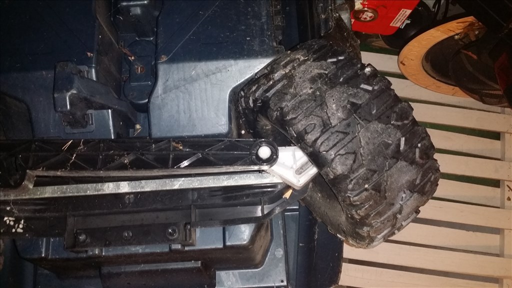
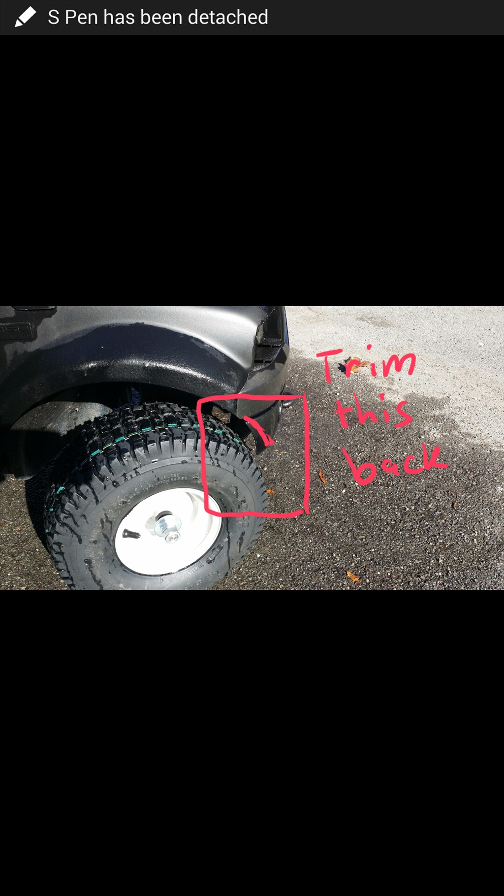
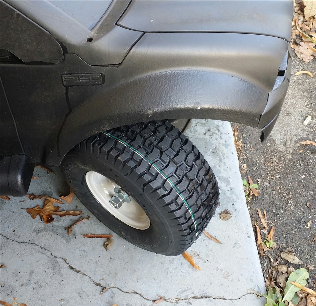
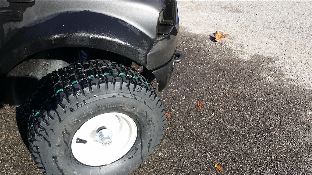
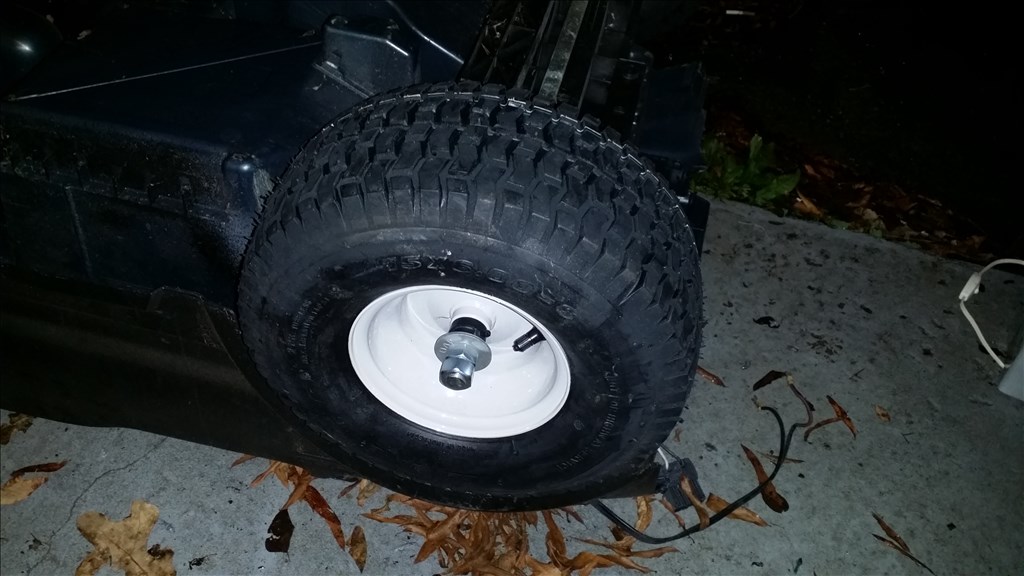
Ok , as promised the sun was out today allowing me to take great progress mark pictures. I tested the range of motion on the tires after I modified the stopping points. The front tire can touch the edge of the front fender so I will trim that back some.

This is turned to the right almost to the point it will rub the fender well which is also the floorboard. I may trim this back to prevent rubbing.
Here is the right wheel turned left and you can see it will barely catch the fender.
Here is the fender area I will trim to get full left turn capabilities.
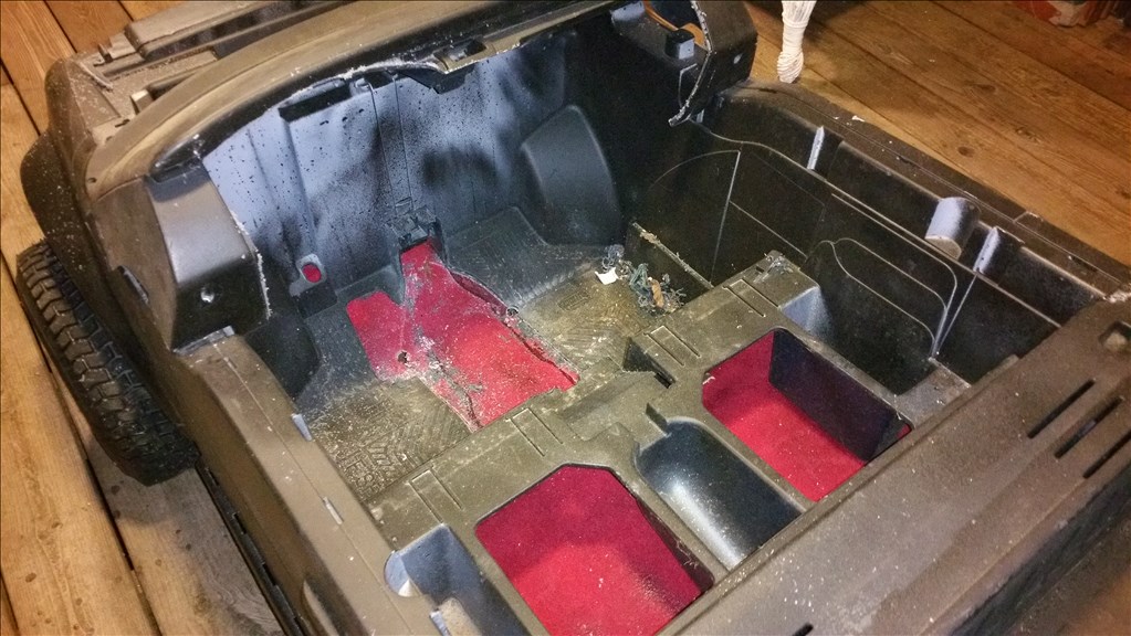
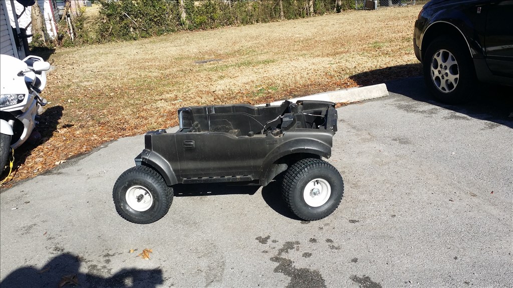
Here is a quick assembly without screws. The project sat outside during the summer and became dirty so I rinsed it off.
Prewash pics, yuck. This is 9 months outdoors unattended.

Ok so slight status update , I will probably cut the threaded rod tommorow for the rear axle and cut it down about 2 inches as it is too long.
I will add the real grease to the bearings and check that the wheels spin freely. Maybe I will do a video.
Cut down the front axle that was a little bit too long on one side and remove the spacers so all the wheels are in alignment.
I need to give this dude a better bath.
Parts list update:
Bluetooth 2.4ghz wireless game pad
Bluetooth headset/ earpiece mic
Windows laptop or tablet for on board
PC ATX power supply to convert the power from the generator to the batteries and the other 12v DC or 5 volt DC items.
SABERTOOTH H Bridge 2 x 12
Pan and tilt cam , either Foscam or other. ( maybe create a custom one)
Buy or build a Larson scanner like KIT
GPS module to interface as serial or UART
LED headlights or trail lights? CREE MAYBE?
Slow moving vehicle triangle
Serial or UART Compass module
Ok, so I have the projects H Bridge. Here is the 2 x 12 Sabertooth which was 79.99. It is pricey but also one of the best controllers available.
I am surprised these things do not come with documentation and a manual.
My 2x25 had a 1 sheet manual in the plastic box under the H-bridge. Fairly basic, but it showed the connections and where to get more infi from their web site.
Alan
Just one more note about the GPS chip. the chip you found certainly looks like it will do the job and you can communicate to it from an EZ-B UART, but you will need to script everything and parse the results. The EZ-B GPS control expects to see a GPS on one of the computer's COM ports, and interprets the NMEA data to give you position information.
NMEA is not complex, and by doing everything through scripting you can also send commands to the GPS (like the quick-start command). But it does add to the complexity of the solution.
Since you plan on having an on-board computer anyway, looking at USB, Serial or Bluetooth GPS devices could save you some money and time.
If you do continue down the path you already plotted (pun intended) Sparkfun actually has a pretty good manual on NMEA 0183 sentences: https://www.sparkfun.com/datasheets/GPS/NMEA%20Reference%20Manual1.pdf
Alan
@Josh, Alan's right... the manual is underneath the foam that the sabertooth was sitting on....
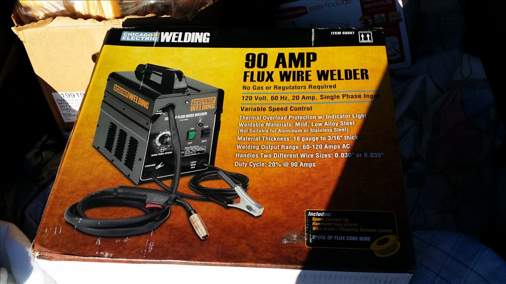
Ok , you are right! I found the manual tucked underneath the foam. Cool beans. I did some black Friday shopping and picked up 3 android tablets cheap and a welder. I have a feeling many of my future projects will benefit from metal. The axles and drive train for a robot for example. I really want a TIG welder for aluminum. Aluminium is cheap , strong, light weight, and doesn't rust like mild steel. The axles for this project are mild steel so I can weld up something stronger for the "version 2" later.
It's a RCA Voyager tablet , I am going to load the SIX program on it and see how that holds up.
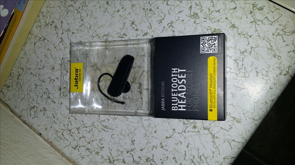
I also picked up a couple bluetooth earpieces that I though I could use to voice control a project.
Those goodies are great finds, now you have the rest of the weekend to continue the hunt.
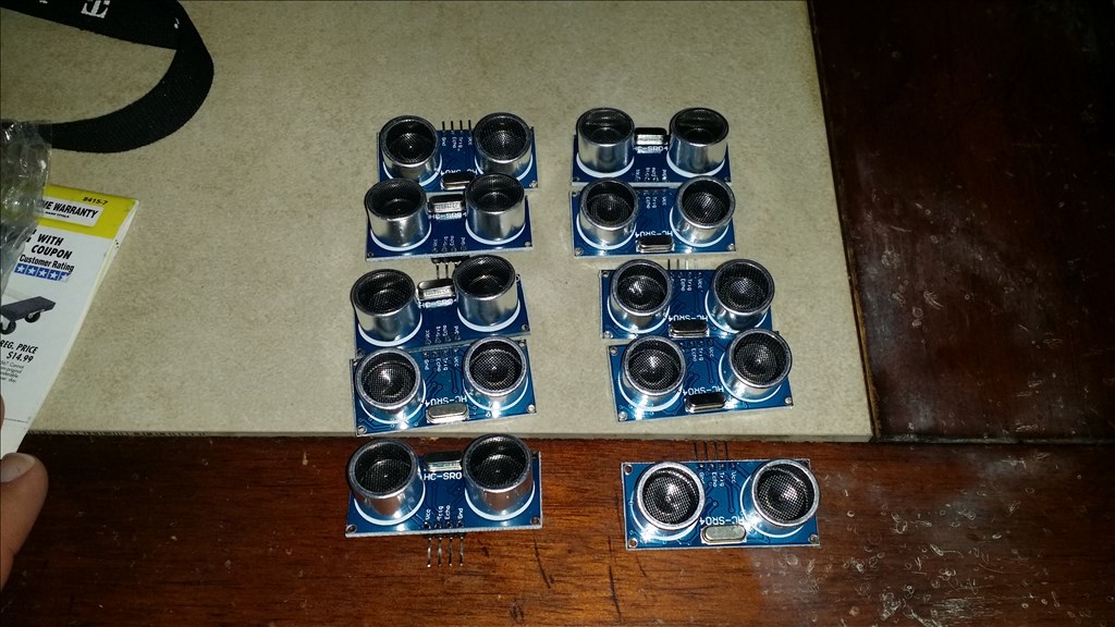
The pack of ultrasonic sensors came from China !
I won a auction for a Acer W3 tablet for this project. I need to find a good "long rang" game pad controller. Maybe wifi or a Microsoft 2.4 ghz game pad? I think there are 2.4 ghz spectrum receivers for Windows pc as well.
jstarne
here some idea.
Hey Josh,
I've used wireless xbox 360 controllers at 75+ Feet with the official wireless dongle for windows. They are 2.4GHz.
Ah ha ! That's what I will grab then. 75 foot range is plenty for this project. I will try to find a good deal on a Xbox 360 controller , rechargeable pack and the windows wireless receiver. Does anyone know if ARC can use the Xbox 360 headset as a mic for voice control? That would be awesome.
Lol Yep I tested it and it works!
Here's a forum post about it.
Sweet! I will pick one up soon as I get a chance. Thanks for the tip!
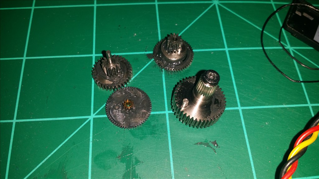
I think that this guy has a upgrade gearbox and aluminum first gears for heavy duty use. Apparently they are for racing.
http://kidcarsandparts.com/power-wheels-327/
I emailed the guy to see if I can get a set of orange gears and aluminum first gear. The orange gears are a thicker nylon with metal bearings so they are not as likely to strip or break.
Ok so I heard back from the metal Gearbox guy and he basically said that I am welcome to upgrade to a metal Gearbox from him which is aluminum gears verses plastic however he's pretty sure I will strip them anyways. He's under the impression I am going to be very hard on this robot lol.
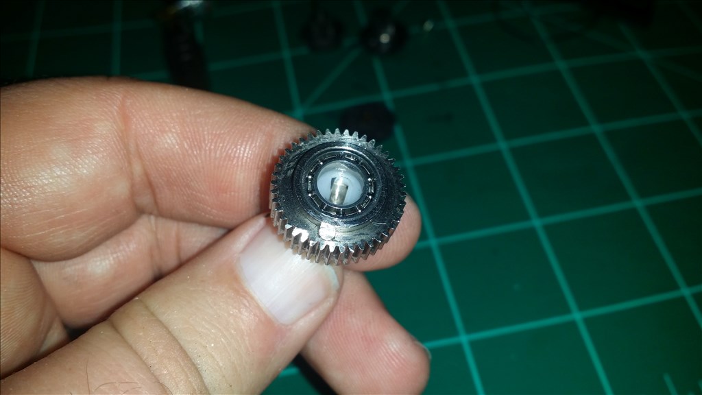
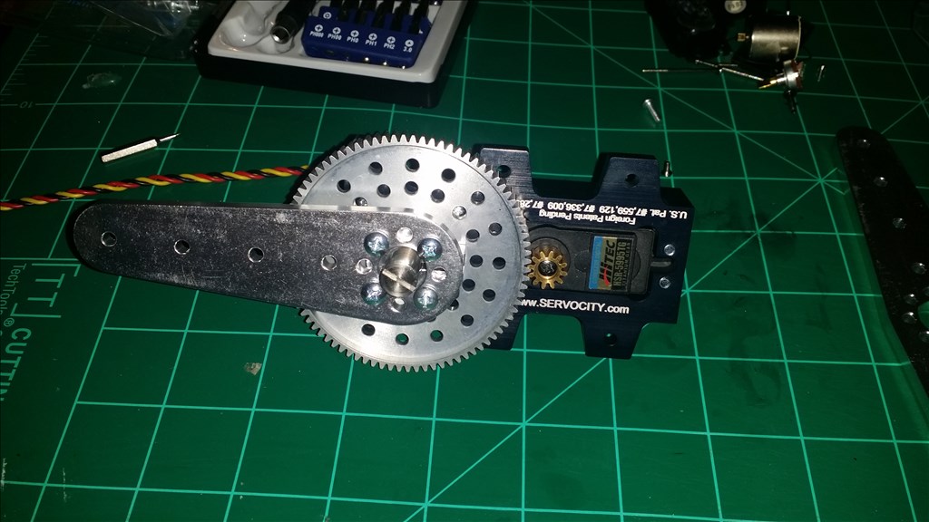
I assembled my Hitec 5995tg in the servo city 7:1 aluminum gearbox. I cannot physically turn this servo now! I am more confident that one servo can make the front wheels turn now. The bad news is I accidentally bike the tabs off a motor in the first servo. It might be repairable , I may send it in to Hitec.
Ok I made a couple short videos in between studying for finals. I found that the hitec 5995tg in the 7 to 1 ratio gearbox seems to be plenty fast for me. Now the next challenge is fabricating a mount the places the gearbox output servo horn as close to the center of the steering rack as possible. I want to try using the second hole for the steering and If possible the first hole on the horn. The closer to the center the more torque I have to move the front wheels.
Servo city 5995tg gearbox speed test. Its really fast for a 7 to 1 ratio gear! http://youtu.be/07YKk4fV7h4
Playing with a test fit servo gearbox and placement options on the power wheels: http://youtu.be/7qoSewF6iIk
Tiny update: Per Jeremie B. suggestion I picked up Wireless Xbox controller with windows USB adapter. It advertises a guaranteed 30 ft range , but Jeremie suggested that it would work for 50 plus feet. I appropriately purchased the matt back one.... it's like I have a theme going here lol.
@Josh,
Looks like things are progressing well. I'm enjoying your vids. Even more so scene I'm using the 7-1 servo gearbox in my B9 arm. Looks like we have some of the same concerns and challenges. Here's a couple thing that pop up for me;
First it looks like the 5995tg servo is currently out of stock or unavailable at most places like servo City and others. It looks like a sweet and strong servo. Sadly the only comparable servo from HiTech that I've found the standard size HS-7950TH. This is what I'm using in my gearbox. Shockingly it cost almost $150 USD. It's as fast and strong as the 5995tg and can take voltage up to 7.4 VDC. More voltage, more torque and speed as you know.
I also was presently surprised at the speed and strength of the 7-1 gearbox with this servo installed. I have it vertically lifting an asymmetrical load of about 3 lbs at the length of about 7 inches or more from the shaft. The 7-1 works so effortlessly I may even be able to down size to a 5-1 gear ratio for more speed.
I did notice the set screw that hols the smaller gear on the main shaft of the servo installed in the gearbox tends to come loose under load. Again as you may know loctite may be needed if you use a metal geared servo. However Karbonite or plastic gears will become brittle and shatter.
I also am in need of some sort of cover or bonnet over the large and small gear set of the servo gearbox. I was thinking something like (as an example only) a plastic coffee can lid. This bonnet could screw right down onto the large gear and extend out over the end enough to also cover the smaller gear. It could also have edges that extend down towards the servo (like the coffee can lid example) enough to cover the gear teeth. In my case this would keep the inside of my rubber arm from wearing across the teeth and catching at that pinch point where the two gears come together. I was thinking of asking Anthony to design and 3D print me something like this. However I think you also may have a printer. If you decide to print something like this I would diffidently like a set of two or more for myself and would be willing to pay for your effort and material.
One question, How do you plan to take in account for the vertical movement of the attachment point at the end of the servo arm to the tie plate (between the wheels) when the servo arcs back and forth? Never mind. I see the extra pivot arm and the servo being off set in your pic. blush
I'll be posting videos of my set up soon. We can compare! :D
Well, thats about it. Keep up the grand work! Dave
Ok , so I decided that I was not happy with the amount of torque with only a single servo. In some ways I predicted this , however I accidentally damaged the second Hitec 5995tg during modification, the power leads to the motor broke from the INSIDE of the motor. I searched ebay and with some patience found a guy selling some 5995tg servos and picked another one up. Also I ordered another 7 to 1 ratio gearbox kit from servo city. Now I will have twice the torque for steering!
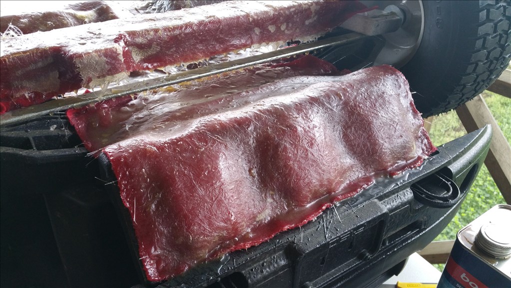
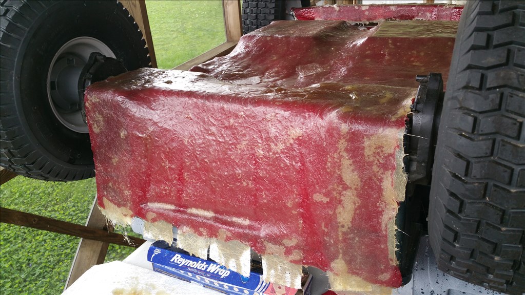
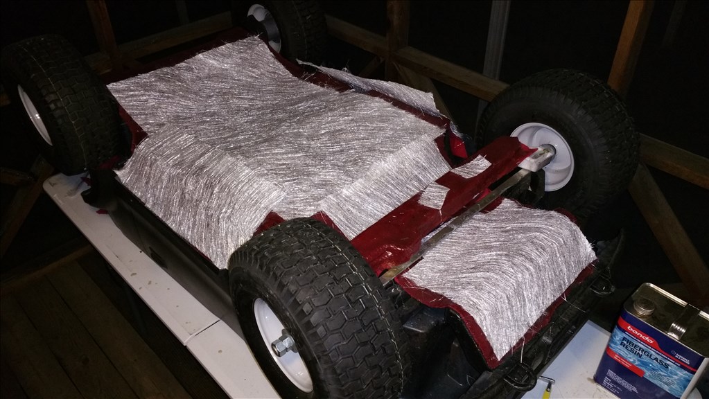
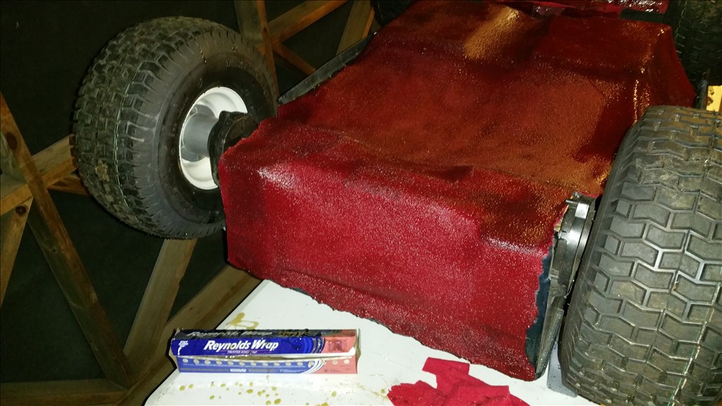
Ok , I finished up the semester and it's summertime. So I get to work on the website Redhatrobot.com (which will be a store where I sell custom accessories and bodies for ez robot products. I pulled the truck out of storage to do some work on it. I ordered the correct gear and pinion as I recieved the most recent one with a 5 to 1 gear. Today I recieved the 7 to 1 gear for the steering column. I attached fleece as a base and next I will saturate it with polyester resin. Once the resin hardens I can reinforce certain high stress areas with fiberglass to make sure this guy doesn't fall apart on the first drive out.
Awesome Josh. Glad to see you back in action, I hope your semester went well!
Hey , thanks Jeremy! And yes it did , all A,s , I managed to get an A on that project you helped me out with too. Thanks :)
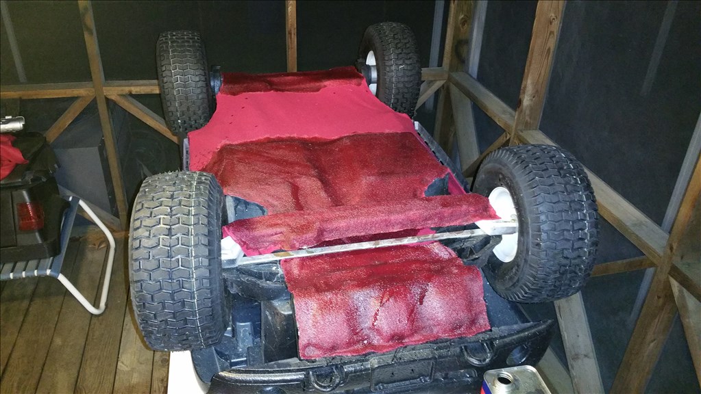
About 1/2 saturated with about 28 ounces of resin. The fleece really soaks it up! Taking a short break then I will finish soaking the base fabric. This base is the bottom layer that will support the actual "fiberglass" as it is being laid down in strips.
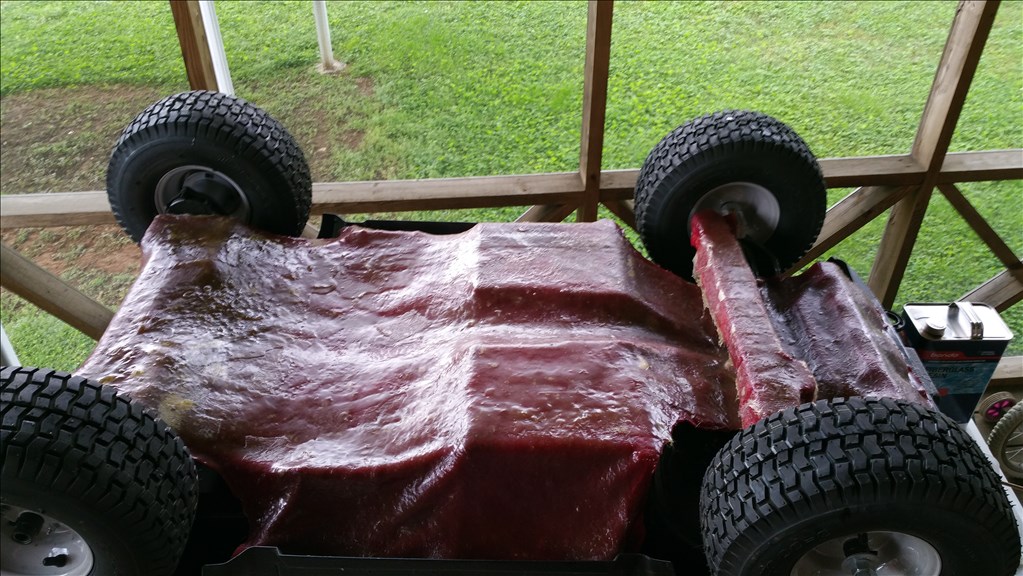
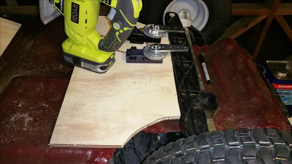
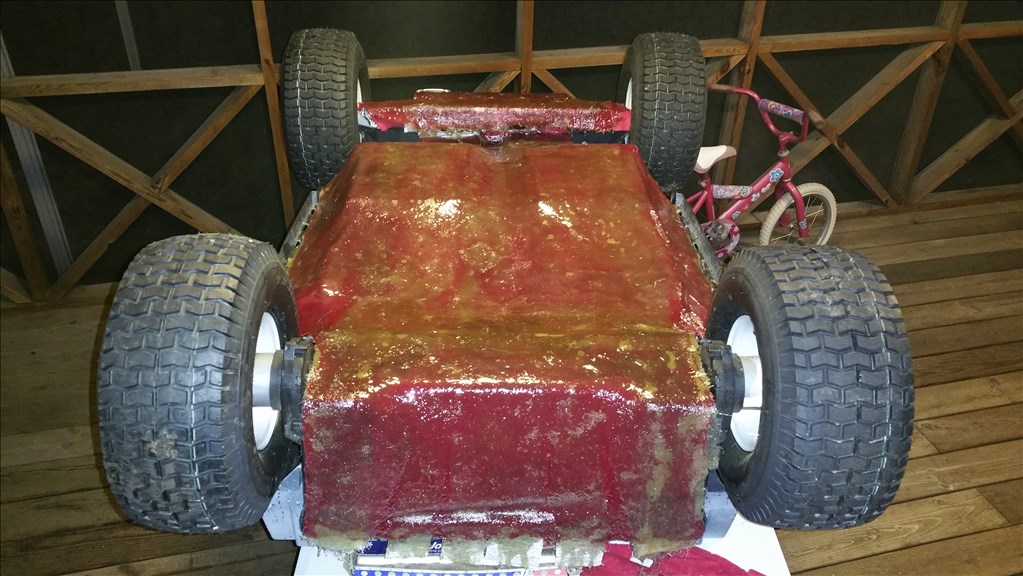
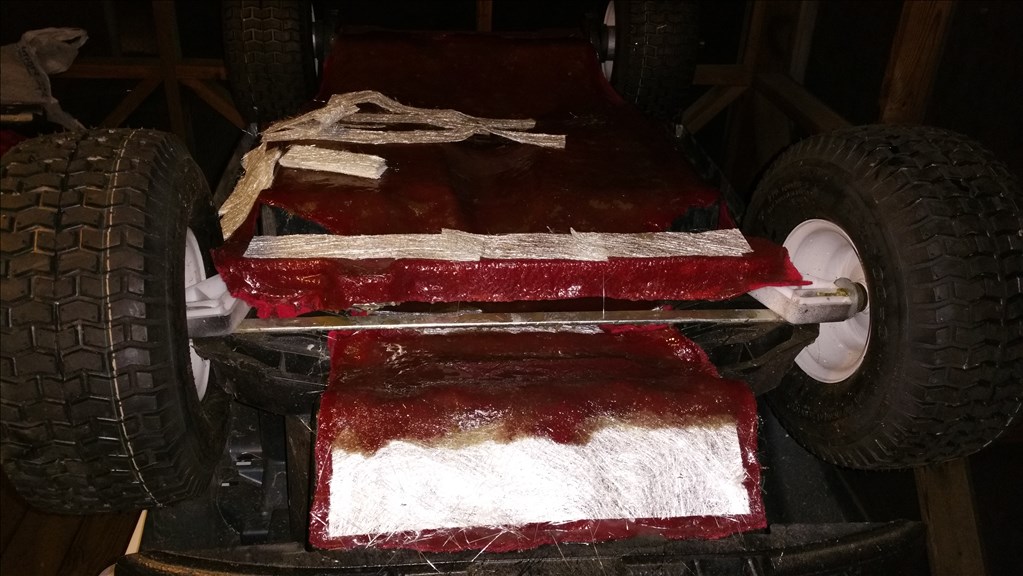
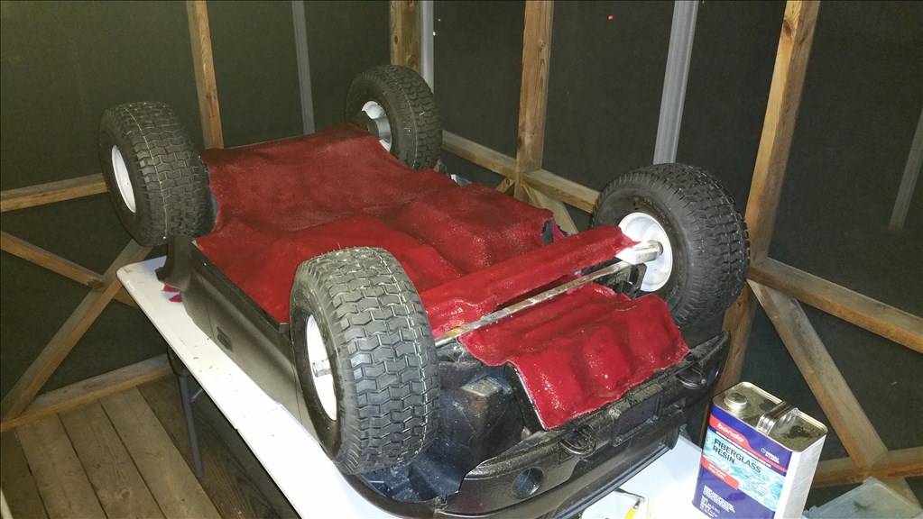
Ok , nearly a gallon of polyester resin later the whole bottom is soaked. 2 hours to harden and then I can add 1 or 2 layers of fiberglass matt. This does two things. The fiberglass bottom reinforces the suspension from flexing too much under weight. Secondly the bottom helps keep the car from getting caught on debris or uneven terrain. Tommorow I will cut out 1/4 inch wood into a mount for the two monster servo gearboxes. I will prop them up with dowl rods and fiberglass the mount on as well. As I have already been suggested , I am thinking of making a removable cover to protect the servos and the gears. The actuation arm will stick out where the steering rack is attached by the aluminum lever.
I've never worked with fiber glass before, looks like messy business I think I'd like to try one day.
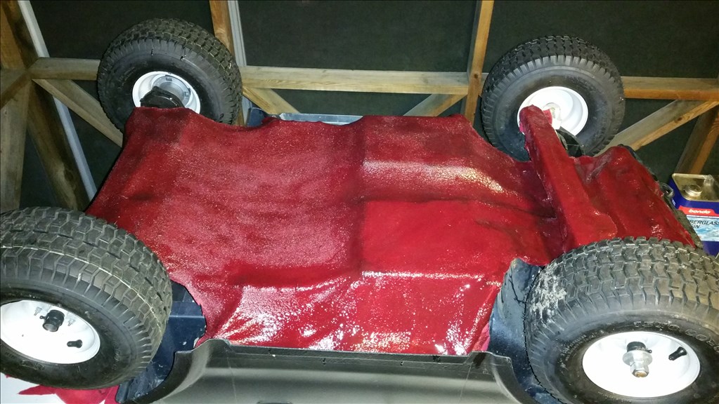
I really like the idea of keeping the underside protected like that, not only will it offer strong protection but it looks professional as well.
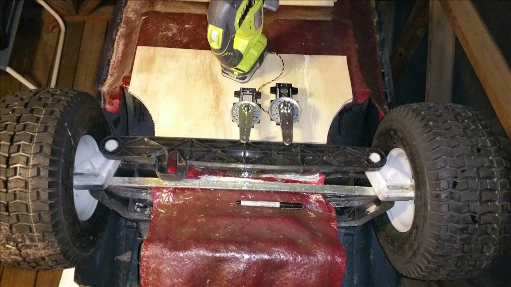
Now that underside fiberglass is done , now the power wheels has a "frame". I made it to be removable but at the moment it is tightly adhered to the bottom. A bit of prying carefully will pop it loose. One continous piece front to back makes the body rigid whereas it was very flimsy before. I'm doing as little modification to the actual car as possible though so I can still refer to it as a "power wheels" ride on toy. The steering must be hooked up and I have two servos to use. Now I am cutting a template for the actual servo gearbox mount, it must be as close to the steering arm as possible. This is so that the tip of the 3 inch aluminum servo arm is centered over the middle of the steering arm.
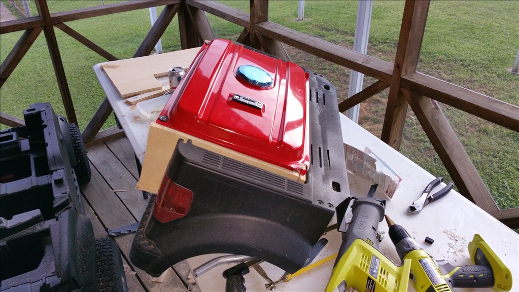
Ok , so now comes the difficult parts. Actually installing equipment in a functional manor. The most important part is the generator but I believe I will remove the original gas tank in exchange for a custom round one.
I pulled out the sawzaw ryobi and cut out the center console as it will never hold a drink for a 5 yr old agian! More importantly it will give a good low center spot for the 63cc generator.
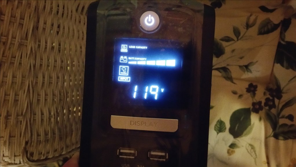
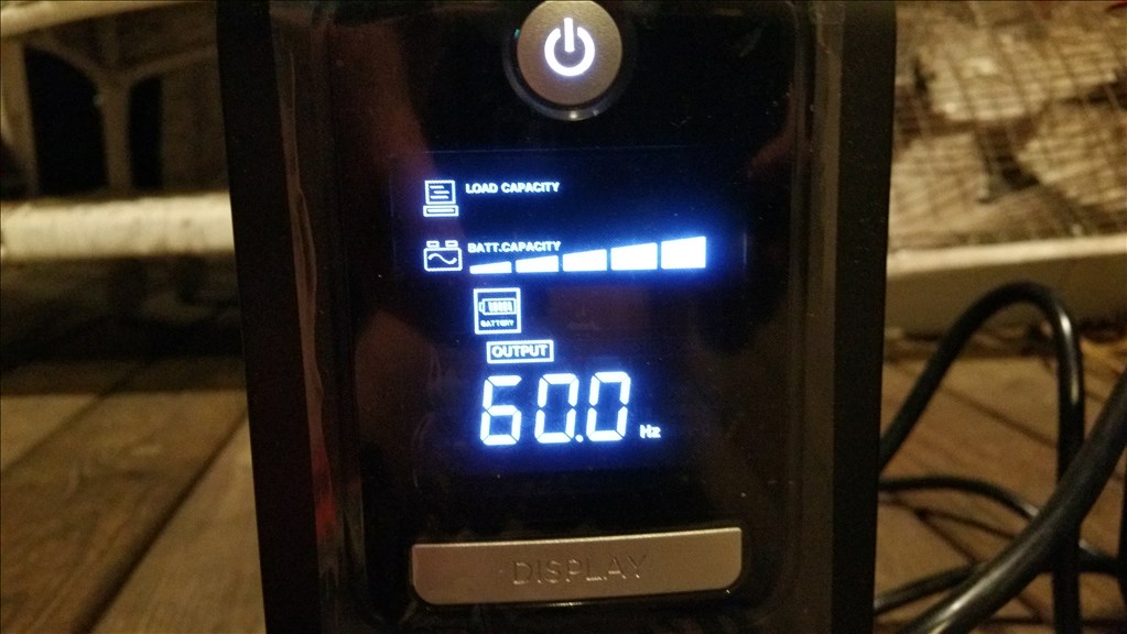
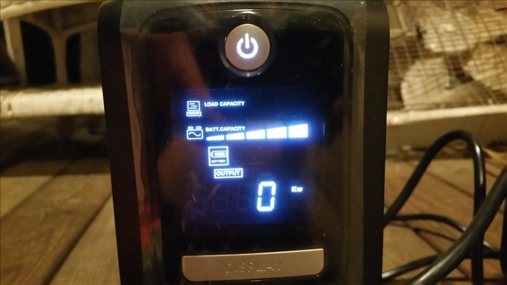
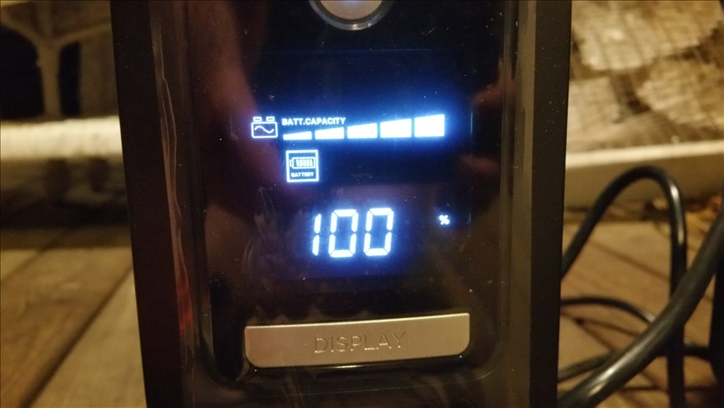
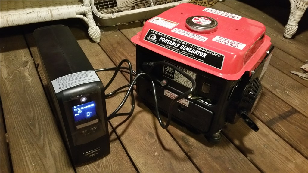
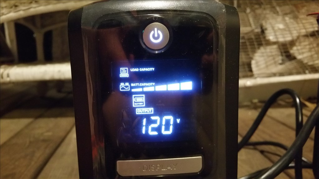
You see the 900 watt battery backup and uninterruptable power supply. I had to test it with the generator and it appears to do its job. The generator produces messy power. I read 129 volts without a load at 60 hz , passing into this power scrubber I get a simulated sine wave output at 120 volts 60 hz. This is much safer for sensitive electronics. I love that this unit from Cyberpower has built in meters for every piece of data related to power consumption. Total watts input , hertz input, voltage input, battery level, battery load , estimated runtime, voltage out, hertz out, watts/amps out ect.
Oh man, this thing is looking better and better each day!
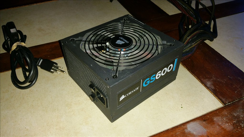
Thanks man! It is coming together , I really wish I kept on it over winter. It would be rolling by now! I bought a Corsair 600 watt psu to hack as a 120v to 12v volt bronze class high amp switching supply for the h bridge , servos and drive motors.
OK , here is the switching power supply that brings the 120 volt down to a manageable 12 volts to work with. I imagine I will be hacking most of this wiring harness off unless I install a desktop style PC in this thing...... not happening lol.
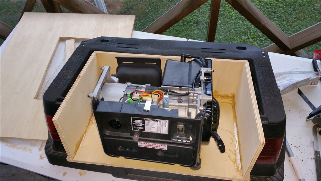
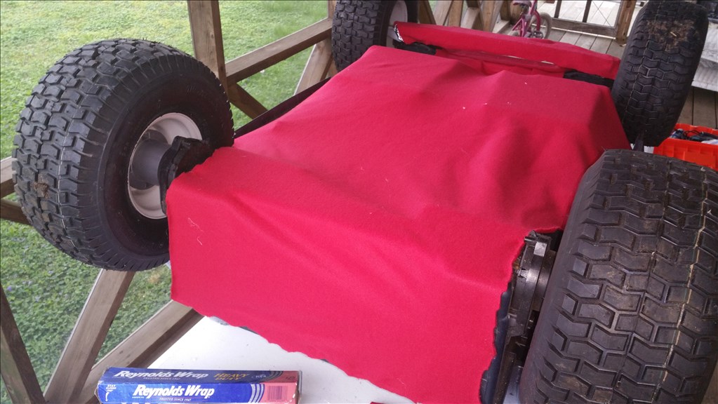
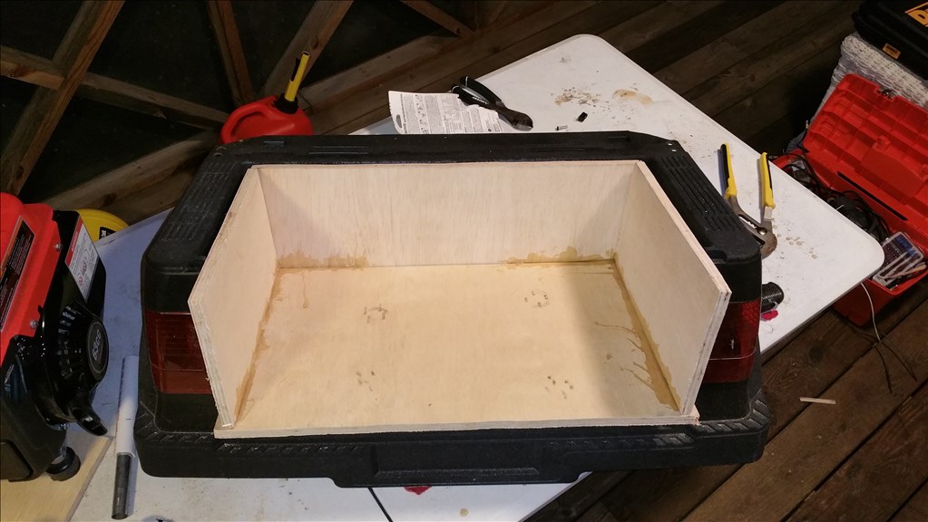
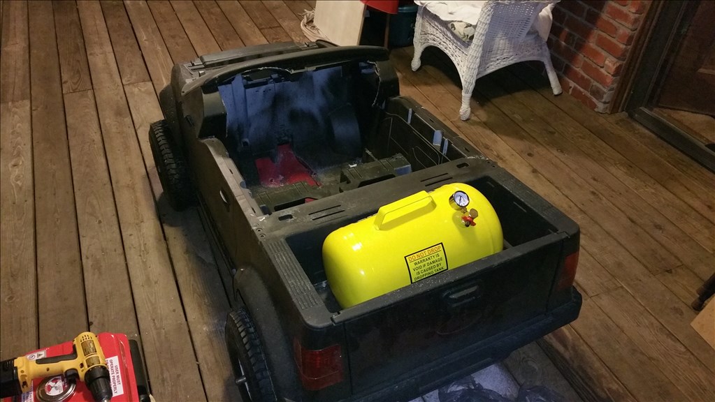
OK so after testing the generator inside the bottom of the car I don't like two things. Number one is it will shift weight to about 60 percent front 40 back. Second is I believe I will kill the generator without open airflow. So that being said I abandoned putting the generator low in the truck. Instead I will mount it in the "truck bed" area and make sure there are a few inches of open airspace all the way around the unit. I am building a wood frame and there will be 2.5 inch holes drilled for the rubber feet. This way the generator cannot slide around, but still keeps all the vibration dampening it was designed for.
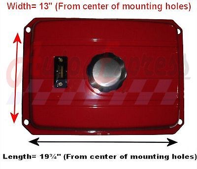
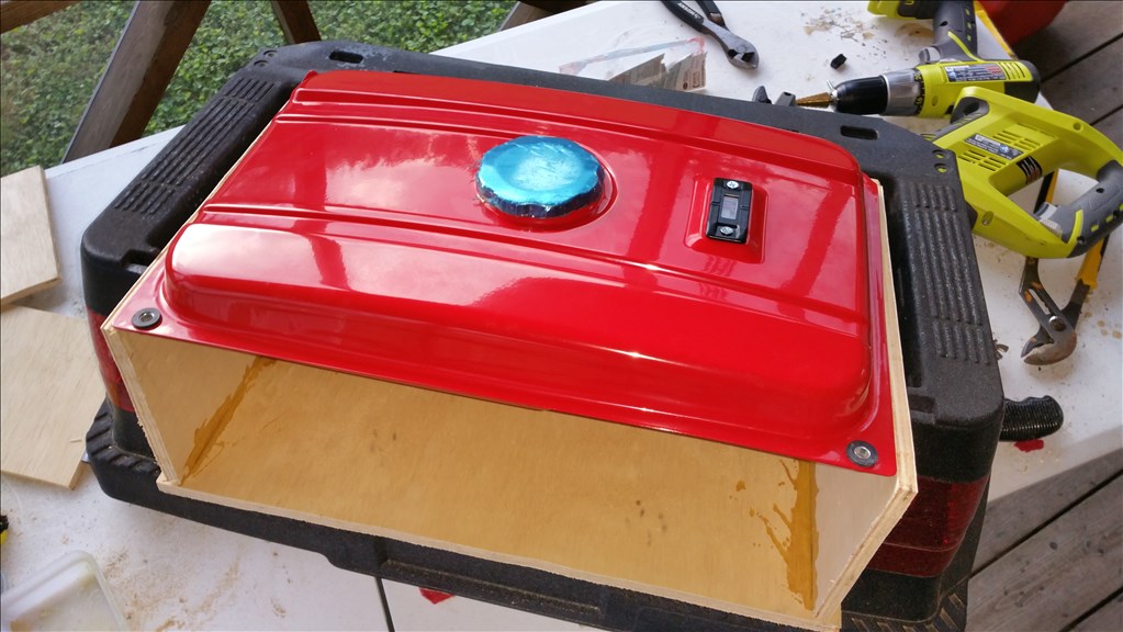
This pic shows measurement's for a replacement fuel tank intended for a 4000 watt generator. It is a 5 gallon tank with petcock valve. The top has a vent and fuel guage as well. Given the comparison of the existing tank the new larger one could fuel the generator at 1/2 load 400 watts for 50 hours continously.
I believe I will completely unbolt the existing one and mount this one over the top instead.
As you can see there is a great deal of open space. Obviously there will be a single cord wrapping around to the front. I could hard wire the 110v but the obvious ability to unplug it gives me a manual safety feature to disconnect from the generator.
A car for a robot is a very nice to have ;-) Thumbs up!
offtopic anybody have TL-files (for 3D Printer) for the NAO? offtopic
Haha Thanks , 4x4 utility Robot , this is version 1 , version 2 will have the same equipment moved over to a steel tube frame and have a legitimate suspension. First I will make some world record attempt's with this "toy" "power wheels" chassis. I will be attacking the current record set by Tamiya, 23 miles in 24 hours.
As far as 3d files.... Anthony is good at 3d design. If you need a part he can probably draw it for you to 3d print. Xlrobots.com
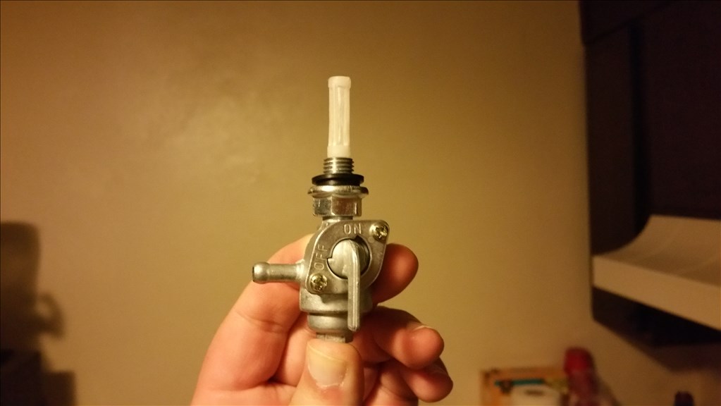
Here is the new petcock valve that screws into the new tank. The tank arrived but a couple mounting tabs were bent. I have two options , I can either mount the tank directly above or slide it forward about 16 inches and mount it there where it can be mounted lower to the center mass of the vehicle. Anyways those are my two options for mounting.
OK so I'm trying to get things mounted at this time.
I have a -600 watt psu EZB v4 Sabertooth controller 1500 watt power conditioner Zotac mini pc 4 gallon gas tank 63cc generator
You should look into a sweet custom safari rack for the top of it! Just to hold all your gear! This way you would have the whole surface area of the top to place gear on instead of having to mount around your gen. This is also a similar idea that the military has been playing with for years now but to build something affordable for the public that really anyone with some basic knowledge of electronics, robotics, and handyman skills can do is an awesome idea! I moded my sons power wheels for 24v but this looks like a project that may be interesting to start as he gets older to teach him some basic knowledge! Great job man!
I am interested in building something like this for a communication robotics lab project at Western Michigan University in Kalamazoo Mi. I understand everything you did but I am not sure how you hooked up the speed controller and servos to the EZ-B. Can you explain or post a pict?
Should be a fun project! I hope to see more progress in the future.
I would bump up the distance the reversing gets triggered at so it's further from the obstacle in case it slides more on different terrain.
My website
I'm wondering if the above post is spam. It was almost a legitimate comment but then there's a website added to the end that doesn't relate.