When I decided to design and build a remotely controlled lawn mower, there were two main requirements that had to be met before the project moved forward. It must be safe to operate while being environmentally friendly. Using 12 Volt DC motors would address the environmental issue by eliminating the need for a noisy, polluting, gas-powered engine. The primary safety concern removed metal blades, spinning at high speed, as a viable mowing option.
Serving as an engineering mentor with a local FIRST team for the past two decades has influenced my personal robot building philosophy. Make it big, strong, and modular, using off-the-shelf components whenever possible. This project would adhere to those same design principles. Those familiar with the FIRST Robotics Competition (FRC) will recognize many of the parts I used and appreciate why I chose them. The design was partitioned into three subsystems: mower head, mobile chassis, and electronics module.
Most of the chassis and power transmission parts come from two vendors, AndyMark and VEXpro. Both companies have broad product lines and are major suppliers to the FIRST community. I have no financial interest in either entity. I only mention this as a service to those contemplating building large robots and needing a source for quality components.
To meet the critical safety requirement I chose to use a PivoTrim Pro Trimmer Head. The PivoTrim head was designed as a universal replacement for most gas string trimmers, but I reasoned I could adapt it for my needs. Since two heads are better than one, at least in this case, using two trimmer heads would cut a double wide (28) swath with each mower pass. I will try to resist the urge of using the phrase cutting edge technology in describing this project.
I took a chance and ordered two PivoTrim Pro trimmer heads online for less than $10 each. Summer garden equipment can be surprisingly inexpensive when purchased during the middle of winter. The design of the mower was centered entirely on the PivoTrim head. Upon delivery and inspection, it was obvious that I chose wisely. A 3/8 diameter hex head bolt mates conveniently with underside of the trimmer head. Timing belts and pulleys appeared to be the obvious solution for spinning the two string trimmer heads.
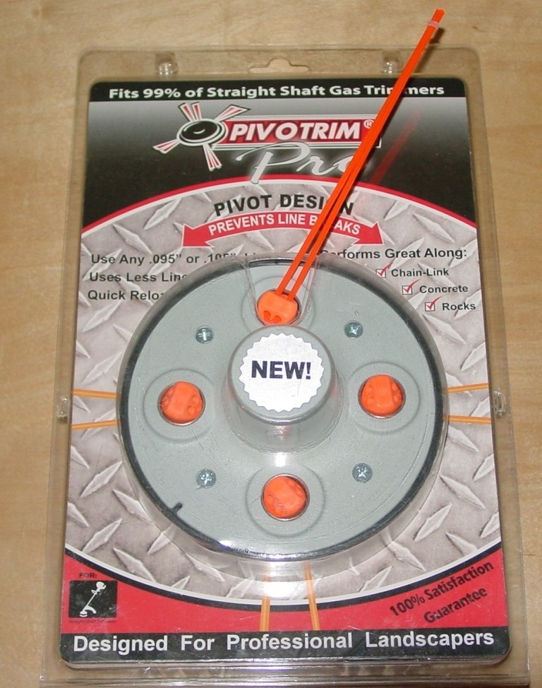
The PivoTrim head
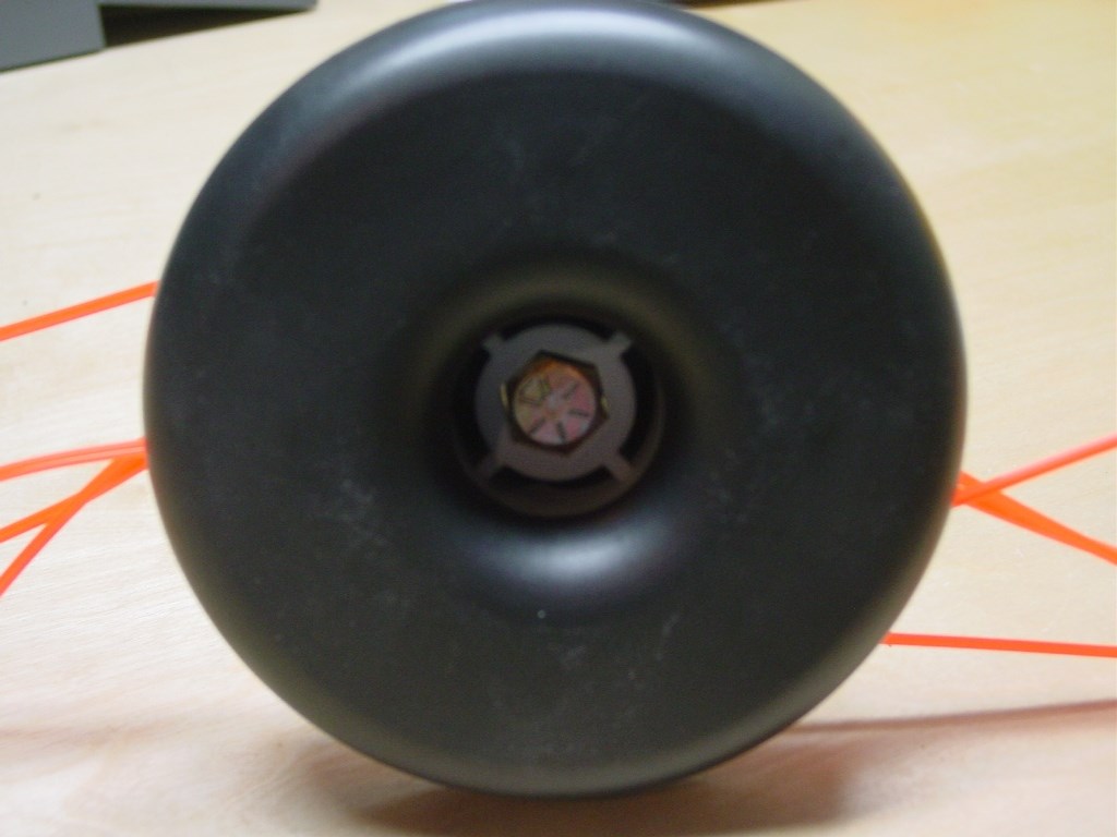
Underside of PivoTrim head
The design process started with a modular frame for the cutting heads. Once constructed, attaching it to a mobile chassis would be a relatively simple task. The mower head frame was built from 80/20 aluminum t-slot extrusions, corner brackets, and joining plates. The frame was designed for a nominal 12 center distance between the motor and trimmer head pulleys.
I fabricated a simple Delrin bearing block for each cutter head shaft from a length of 1 x 2 bar stock. Two 3/16 thick aluminum plates were cut to length and drilled for mounting the AndyMark CIM motor brackets. Sliding the motor mounts in the t-slots allows easy adjustment of the timing belt tension.
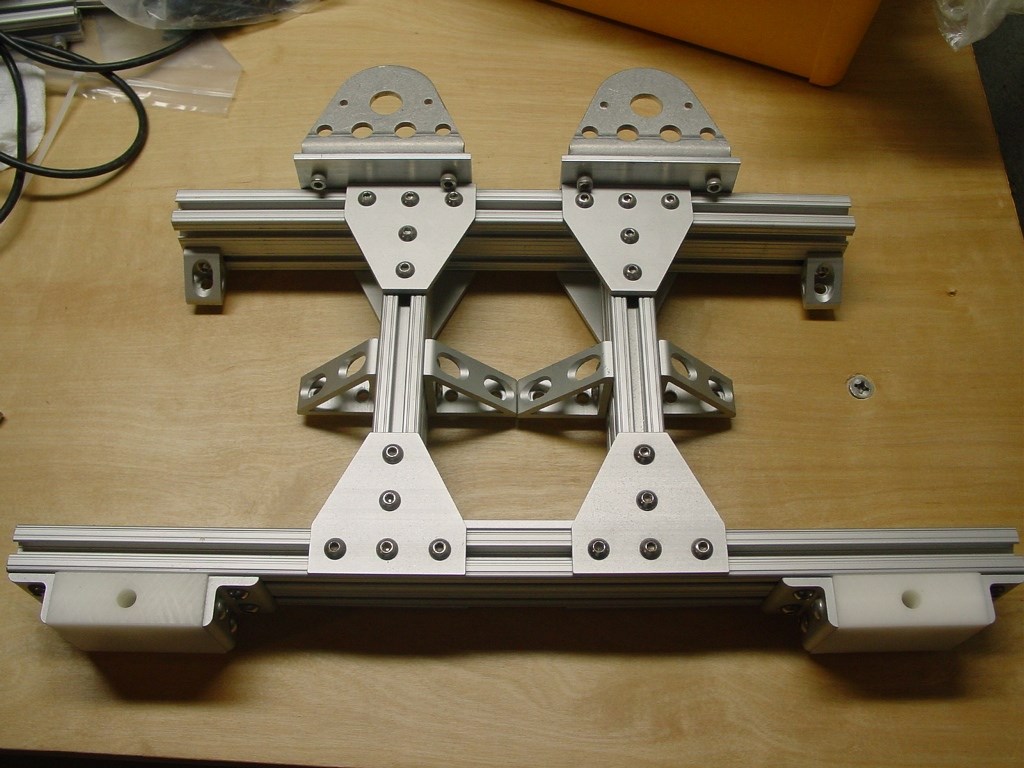
80/20 Cutter head frame
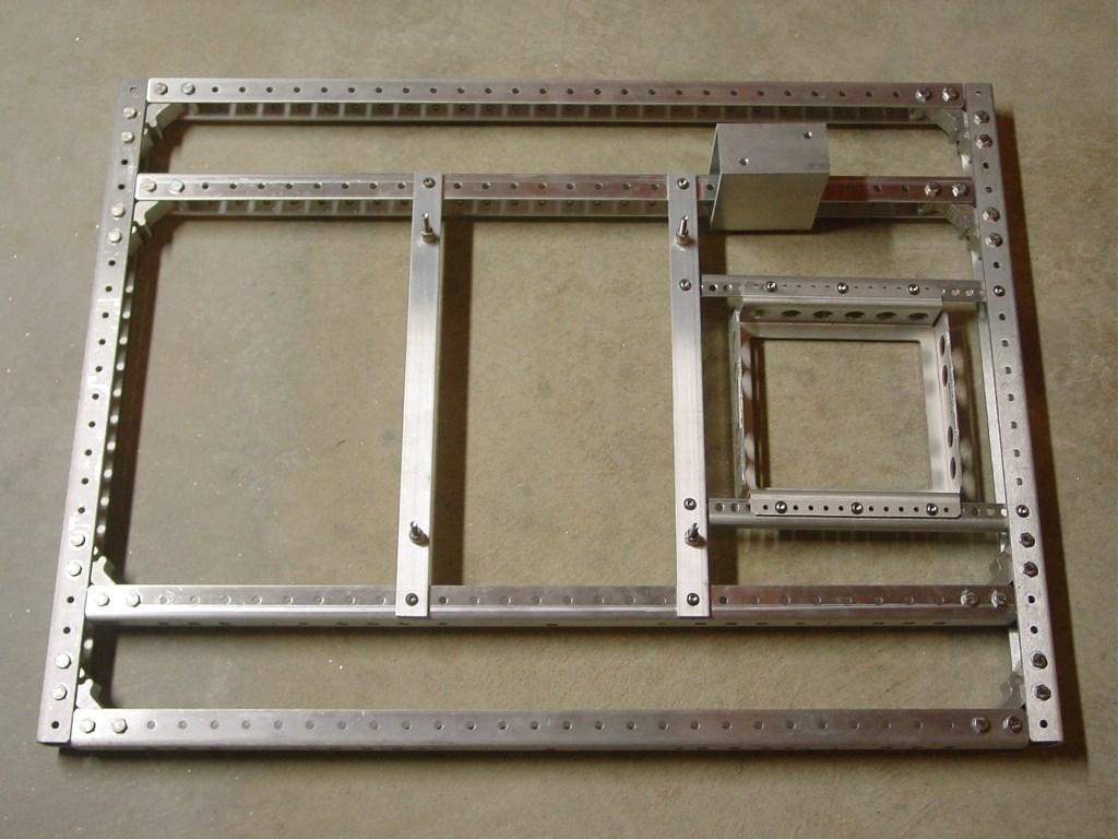
Next, the robot chassis was built from six 30 lengths of AndyMark C-channel and eight C-Base corner connectors. After cutting two end rails to 24, the 24 X 32 (9 lb) aluminum chassis was assembled with ¼-20 bolts and lock nuts.
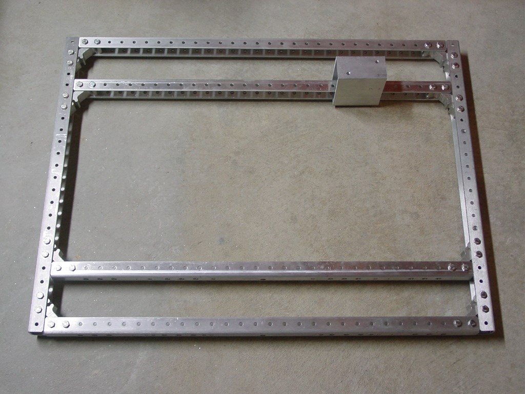
AndyMark C-Base Chassis
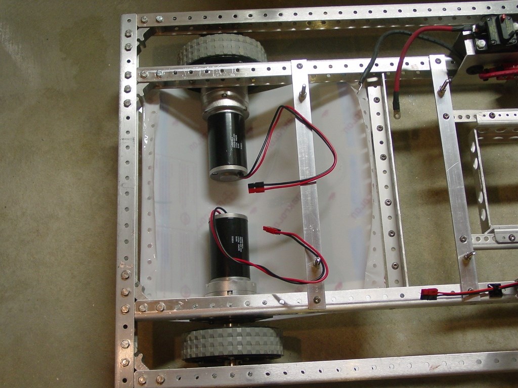
Besides the trimmer heads, the other critical component selection involved the motors and transmissions for robot locomotion. Due to the certainty of airborne dirt and organic matter while mowing, the transmissions need to be sealed units. An open frame gearbox or exposed sprockets and chain would not be practical. I chose to use two AndyMark GEM500 planetary transmissions driven by 2.5 diameter CIM motors. The 2 stage transmissions have a gear ratio of 13.5:1, and mate easily with the CIM motors. The 2.8 lb CIM motors have been the standard propulsion choice for FRC robots for over a decade. The drive wheels mount directly on the ½ diameter output shafts of the transmissions.
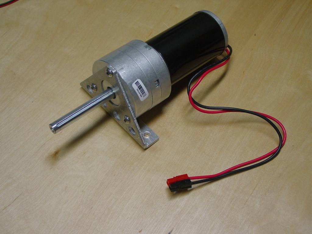
CIM Motor and GEM500 Planetary Transmission
For the main drive I used 6 diameter, 1.5 wide VEXpro Traction Wheels with a pair of keyed VersaHubs per wheel. The rear wheels were AndyMark 4 diameter Omni Wheels with ½ diameter bearings. 5 long hex head bolts served as the rear wheel shafts.
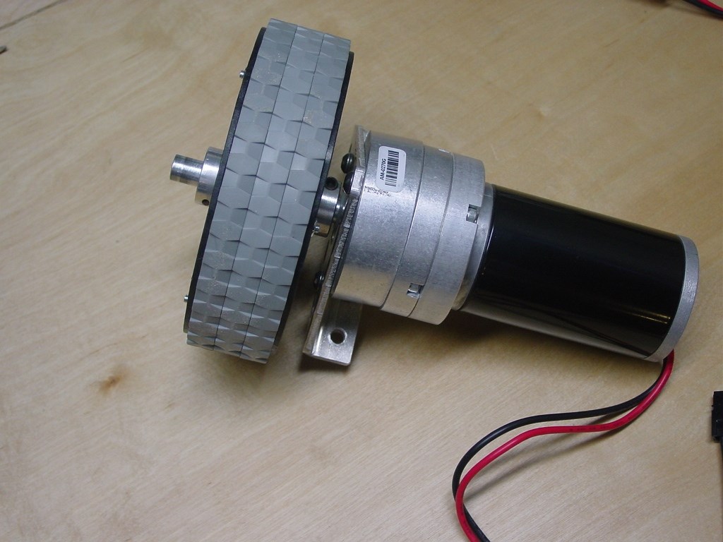
CIM motor/transmission/6" wheel assembly
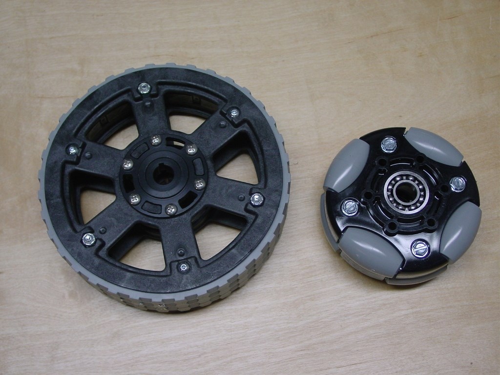
Front traction wheel and rear Omni wheel
The only parts that needed to be fabricated for the complete rolling chassis were the four 3/16 thick aluminum plates to support the rear wheels and the two bushing blocks to support the ends of the planetary gearbox shafts. Self-aligning bronze bushings were used to accommodate any minor flexing in the chassis while travelling over rough ground.
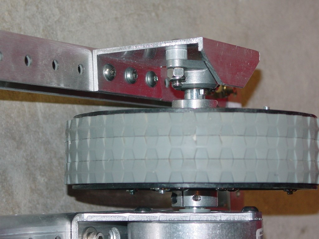
Close up view of front wheel bearing block
After a motor and transmission break-in period on the bench, wheel speed averaged 375 rpm @ 12.5V. This gave a theoretical maximum robot velocity of 9.8 feet/sec. or 6.6 mph. Electronic speed control will reduce this down to a more manageable level.
Due to the low ground clearance of the motors and transmissions, a 1/16 thick polycarbonate skid plate was added to the underside of the chassis to protect these vital drive train components.
Skid plate installed
To finish the chassis structure, two 1 wide X 3/16 thick aluminum bars were cut, drilled, and mounted to the center of the chassis to support the electronics enclosure. Two VEXpro accessory rails support a VEXpro battery box mounted at the rear of the chassis. A short length of rectangular aluminum tubing was attached to one of the inner chassis rails for the main power switch and the battery connector.
Completed chassis frame with rails for electronics and battery box
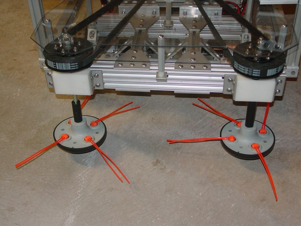
Installation of the cutter head frame onto the chassis was seamless, with the holes in the 80/20 corner brackets aligning perfectly with those of the front and side chassis rails. I love it when a plan comes together. Two Mini CIM motors with 24T pulleys drive the trimmer heads. A 10 long, 3/8 diameter bolt was used as the trimmer head shaft. A 60T pulley was attached to the shaft with a keyless bushing. Tightening the hex portion of the keyless bushing with a wrench causes outer fingers to contract and clamp onto the shaft, while the inner fingers expand and hold the pulley in place. A 170T, 5mm pitch HTD, 15mm wide timing belt connects the two pulleys. At full power the trimmer heads turn at 2400 rpm. Individual electronic speed controllers will be able to vary speed and direction for each trimmer motor. To keep debris from below and fingers from above away from the timing belts, two 1/8 polycarbonate belt guards were constructed and attached to the mower head frame.
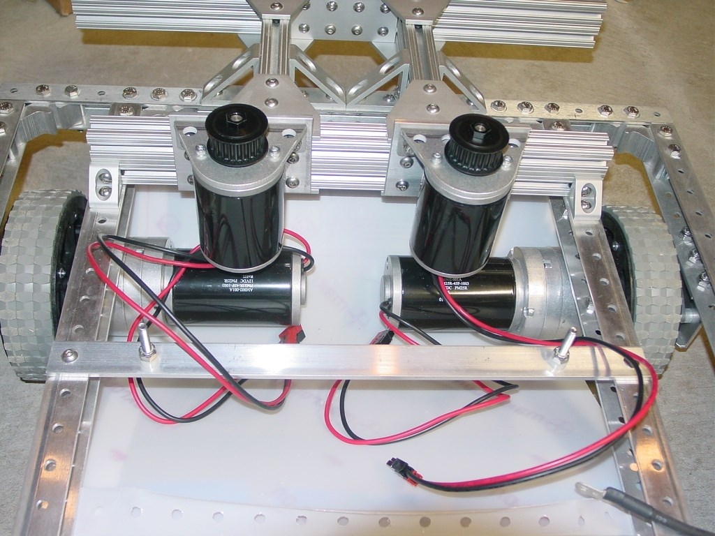
Mower head frame and Mini CIM motors installed onto chassis
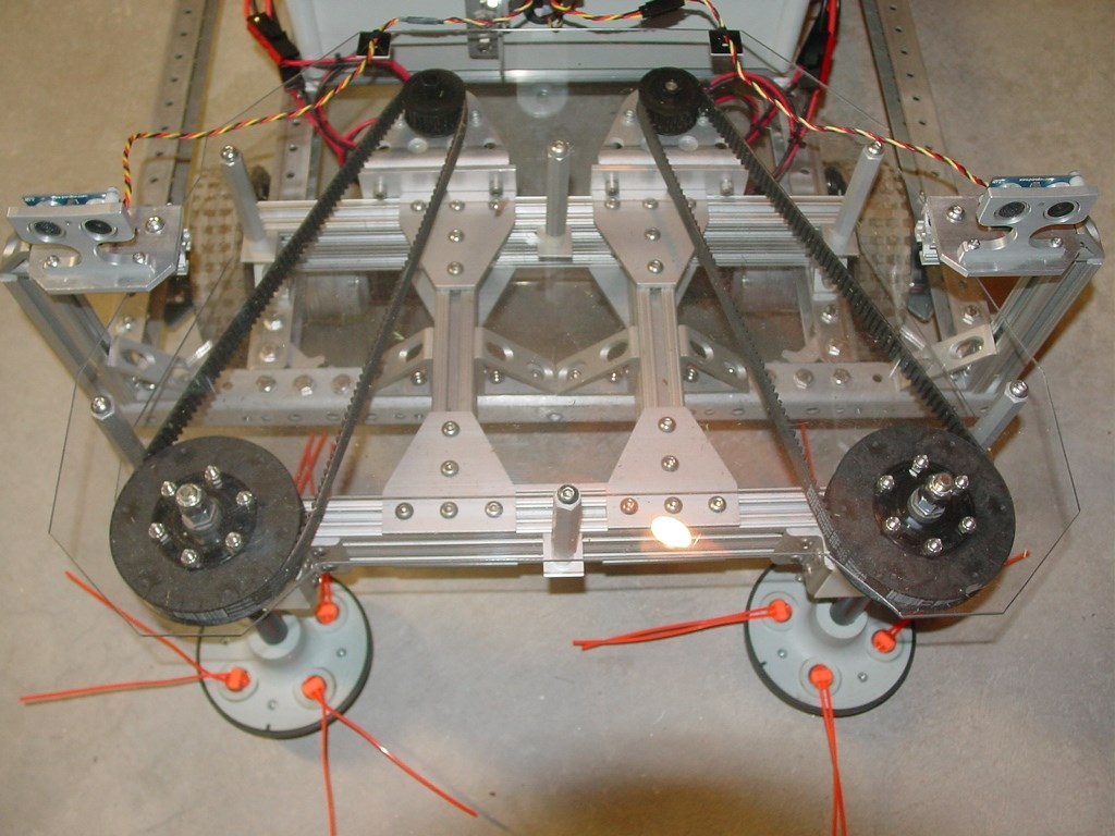
Front view of completed mower head with shielding
An emergency stop switch was added at the rear of the chassis. Activating the E-Stop switch instantly disconnects the 12V battery power going to the EZB controller. With no PWM signals from the EZB to the Talon SR electronic speed controllers all four motors will immediately stop running.
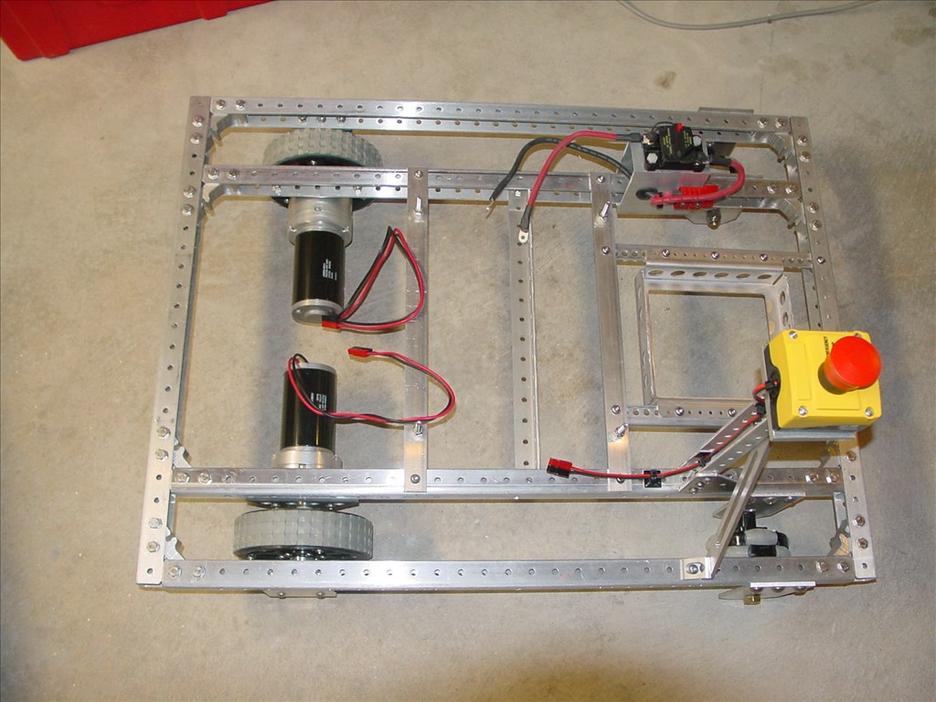
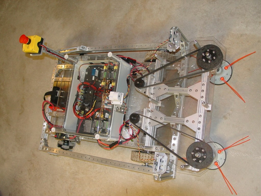
Rolling chassis with E-Stop and main power switch/battery connector installed
Even though the video camera will be the primary means of feedback while the mower robot is in operation, some secondary feedback was considered. Two Parallax ultrasonic PING sensors were installed on adjustable 80/20 mount at to the front of the chassis. The intent is to disable the trimmer motors when an object is detected within a specified proximity limit of the sensors. Depending on how well the PING sensors work in an outdoor environment, replacing them with analog IR range finder sensors to provide this additional level of safety will be a simple task.
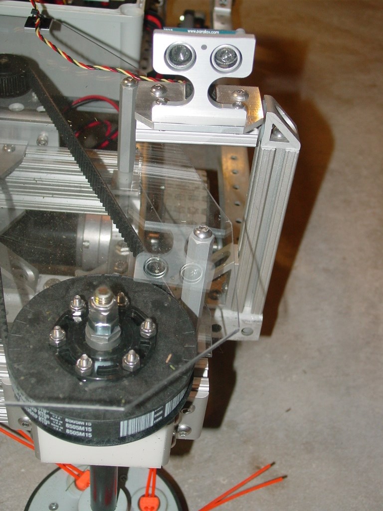
Front mounted PING sensor
The electronics are housed in a large plastic project box with a clear cover. Except for four wiring access holes with rubber grommets, the electronics module is a sealed unit. All the electronic components are mounted of a 1/8 thick, drop-in panel, pre-wired for power and control signals. Due to vibrations likely to be encountered while mowing, the EZ-B power shell was modified by removing the top and bolting the board stack to the ABS panel. A Talon SR electronic speed controller was installed for each of the four, heavy duty, 12 Volt motors, powered via individual 30 Amp resettable circuit breakers. A 12V DC-DC converter provides 5 Volt/5A power to the EZ-B and the digital ports. The LED digital meter displays either the raw battery voltage or the EZ-B supply voltage. A tilting mount for the EZ-B Wi-Fi camera was installed on the front of the electronics module.
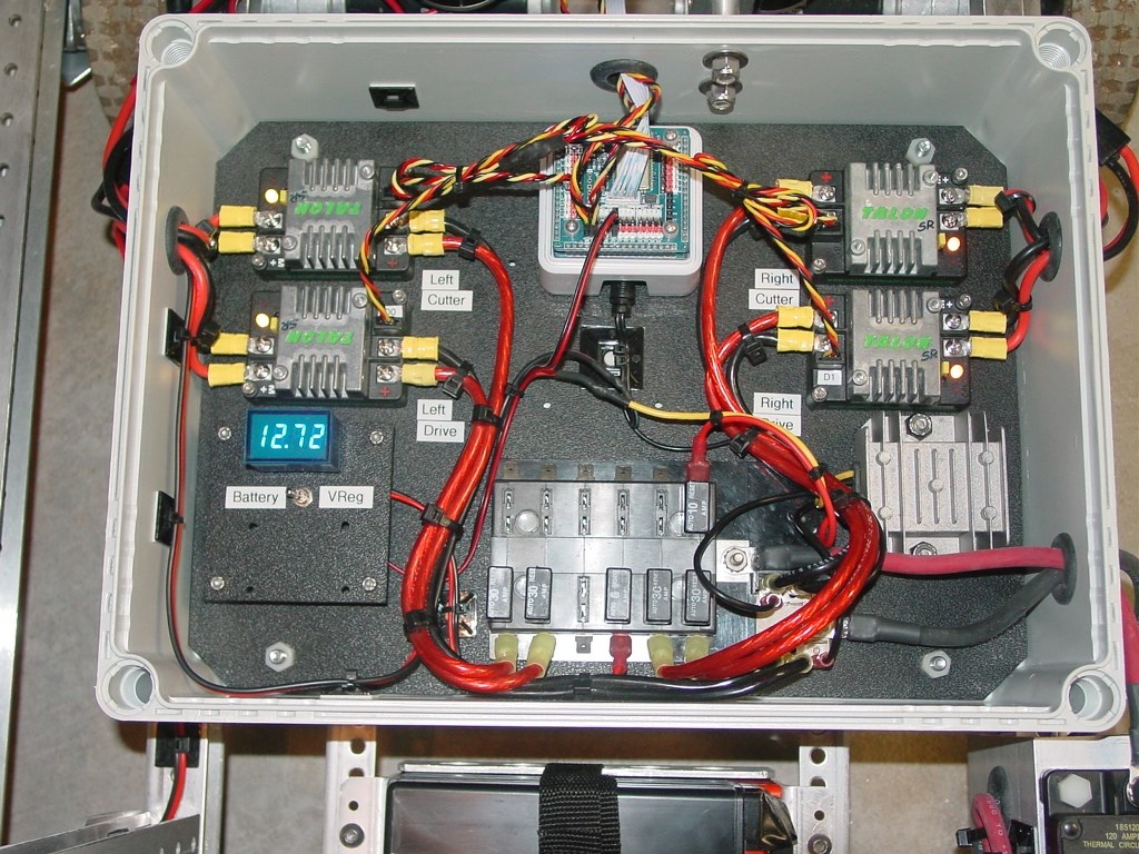
Electronics module
The mower worked as designed. However, I do plan on making some improvements. The next version will feature 4WD for better handling and larger wheels for increased ground clearance. Also, the camera will be located higher up and farther back to get a better field of view.
Front view
Completed mower
Other robots from Synthiam community

Steve's Artamus, The Rambo Knight Robot Hack

Animator28's AVA (Advanced Visual Android)


Beautiful build.
Alan
Very nice design, great craftsmanship and construction. I've used a similar 4 port cutting head on a 4 cycle gas powered weed wacker and got better performance by removing two of the ports.
@thetechguru Alan, thanks. This was the first robot I've built that actually did something useful.
@Robot-Doc Thanks for the tip. I'll definitely have to try that.
Awesome project and thanks for posting.
Damn, I need to get me some Vex Pro framing.... Regular vex is ok, but not great for heavier projects like the inMoov..... Nice work!
Great project. I am looking forward to more updates on it.
http://www.wordsiseek.com/lawn-mowers/
Would like to see a video of it in action. Would also like to see how you did cutting path planning, or does this just wander around like a roomba?
@kamaroman68 Sorry, I don't have any video. The mower will be undergoing some planned improvements for next season. It does not run autonomously. I use the EZ-B camera and a joystick to control it. Unfortunately, the field of view for the EZ-B camera is too narrow. I will probably use a different camera with a wide angle lens and an external transmitter for the video feed.