Setting Up L298n H-Bridge This tutorial assumes only a single combined speed control for both motors. For independent speed of each motor the tutorial will be slightly different - See post #2 of this topic.
Assuming ports D15, D16, D17, D18 & D19 D15 Signal > Left Trigger A (In 1) D16 Signal > Left Trigger B (In 2) D17 Signal > Right Trigger A (In 3) D18 Signal > Right Trigger B (In 4)
D19 VCC > H-Bridge 5V D19 Ground > H-Bridge Ground D19 Signal > H-Bridge ENA & ENB
D19 Signal will need to be connected to 2 pins on the H-Bridge and the jumpers on the H-Bridge removed. I made a Y cable out of a couple of jumper cables.
Connect the positive of the battery to the H-Bridge VCC
Connect motor 1 to the Out 1 and Out 2 terminals Connect motor 2 to the Out 3 and Out 4 terminals
In ARC add a 4 Wire H-Bridge control and a PWM control.
Set up the H-Bridge control as the above D15 to D18 on LTA, LTB, RTA and RTB Set up the PWM control to D19
To use, set the PWM to 100% (or a lower value if you want it slower) - I have mine set to 100% in an init script that is run on successful connection of the EZ-B. Use the H-Bridge control and the motors should move.
Here is a project with both controls added, you can save it and merge it with your project (or open it and test the H-Bridge). It's also accessible in ARC by opening from the cloud.
Note: The PWM wire is optional. If you wanted to save a digital port and lose speed control you could connect any of D15 to D18's VCC to the H-Bridge 5V and any of the D15 to D18's Ground to the H-Bridge Ground. Keep the jumpers on between ENA and 5v and ENB and 5v.
If your H-Bridge looks different, they are pretty much all much of a muchness. A H-Bridge generally has 4 inputs to control the 2 motors plus 1 or 2 inputs for speed control. The same principle as above can be applied.
Signal wires from Digital ports to each of the inputs to control the motors. Generally labeled In1 to In4 or AIn1, AIn2, BIn1 and BIn2. Signal wires (this can be combined for 1 port if you don't want individual speed control from side to side) for the PWM or speed. Generally labelled as ENa and ENb. +5V or VIn is generally the 5V from the EZ-B Vm is generally the supply to the motors taken from the battery. Ground is always Ground, taken from any ground since it's a common ground.
A simple truth table for how the H-Bridge works.
 In4 | In3 | In2 | In1 | Function
-----+-----+-----+-----+--------------
  0  |  0  |  0  |  0  | Stop/Free Wheel
  0  |  0  |  0  |  1  | Motor 1 Forward
  0  |  0  |  1  |  0  | Motor 1 Reverse
  0  |  0  |  1  |  1  | Motor 1 Brake
  0  |  1  |  0  |  0  | Motor 2 Forward
  1  |  0  |  0  |  0  | Motor 2 Reverse
  1  |  1  |  0  |  0  | Motor 2 Brake
So to use that on the robot, setting digital to on (1) and off (0) as follows
 In4 | In3 | In2 | In1 | Function
-----+-----+-----+-----+--------------
  0  |  1  |  0  |  1  | Robot Forward
  1  |  0  |  1  |  0  | Robot Reverse
  1  |  0  |  0  |  1  | Robot Turn Left (or right depending on motor orientation)
  0  |  1  |  1  |  0  | Robot Turn Right (or left depending on motor orientation)
  0  |  0  |  0  |  0  | Robot Stop
EZ-B V4 Usage
With the EZ-B V4 there is a slight difference when connecting the L298n H-Bridge up in that the Vcc pins of the V4 have the same voltage as VIn i.e. if you supply the EZ-B V4 with a 7.4v 2s LiPo battery you will get 7.4v on the Vcc pins of the EZ-B.
The L298n H-Bridge, as previously explained has a terminal for +5V which, on the EZ-B V3 was fine to supply from one of the digital ports Vcc however with the V4 this is not the case.
Rather than supply the L298n with +5V we need to not connect this terminal and press the switch on the H-Bridge so that it uses it's on board regulators to provide its own 5V from the Vcc supplied.
All other connections remain as previously explained.
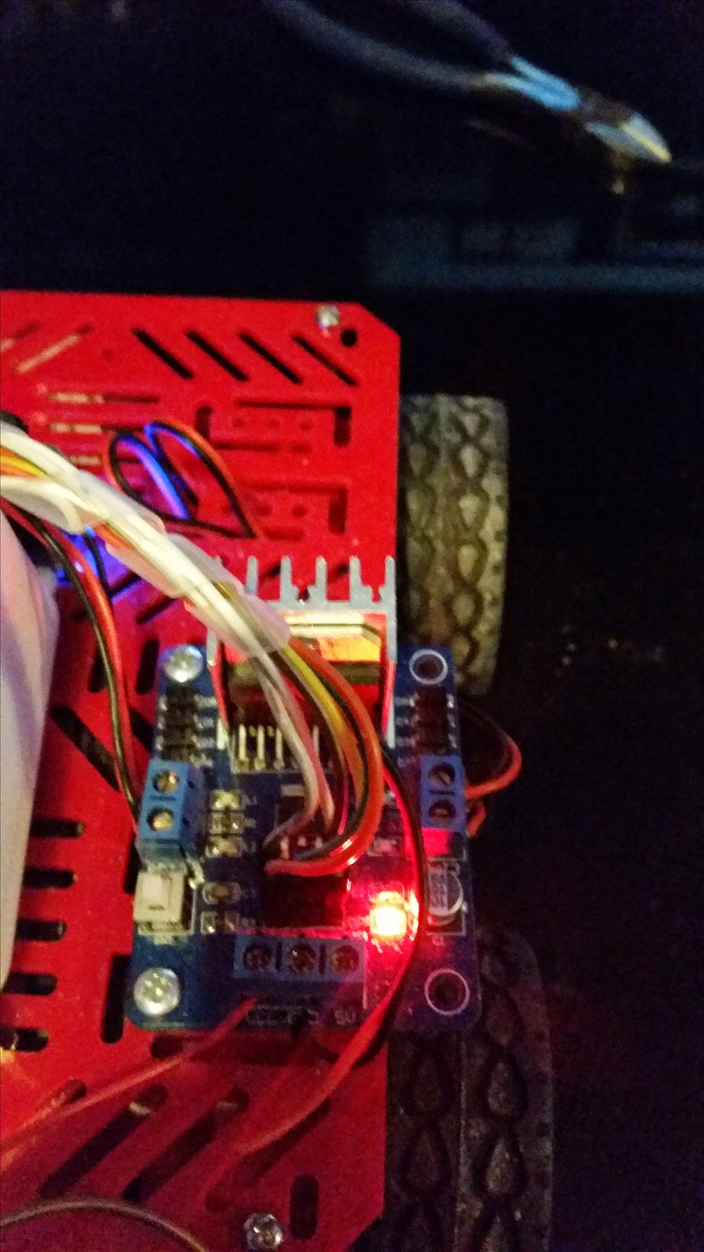
Pushing this button will enable the on board regulators. When enabled it may indicate so with a red LED.
On the EZ-B side, the connections would be pretty much as previously with the exception of the Vcc. On upgrading my test bot I simply disconnected the Vcc on the H-Bridge side so that my connections wouldn't require changing.
On the H-Bridge side, connections remained the same as previously however the +5V is disconnected.
That's all there is to it. :)
Update: 17/06/2014 (or 06/17/2014 if you write your dates wrong...)
Alternative wiring for a simpler method
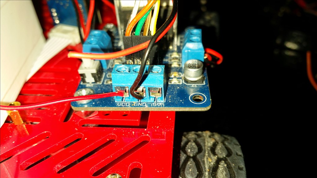
The connections on the L298n are simply;
Vcc = Motor Supply Positive Gnd = Motor Supply Ground (ensure this is common if using more than one supply) +5V = Not Connected
In1 = Digital Port Signal (i.e. D8) In2 = Digital Port Signal (i.e. D9) In3 = Digital Port Signal (i.e. D10) In4 = Digital Port Signal (i.e. D11) EnA = Digital Port Signal (i.e. D12)* EnB = Digital Port Signal (i.e. D13)*
- EnA & EnB connections optional for speed control, If speed control is not required connect the two jumpers which come with the L298n to link EnA to the +5v pin to it's right and EnB to the +5v pin to it's left. If combined speed control is required (i.e. one speed control for both channels) a Y-cable can be used to connect both EnA and EnB to one Digital Port Signal (i.e. D12).
No ground or Vcc from the EZ-B to the L298n is required if you have a single source for both EZ-B and L298n or if you have a common ground.
You must make sure you press the switch to enable the on board 5V regulator circuit otherwise it will not operate
Some photos (I'll change them once I get chance to edit and tidy them up but no idea when I'll get the chance so here's the unedited ones).
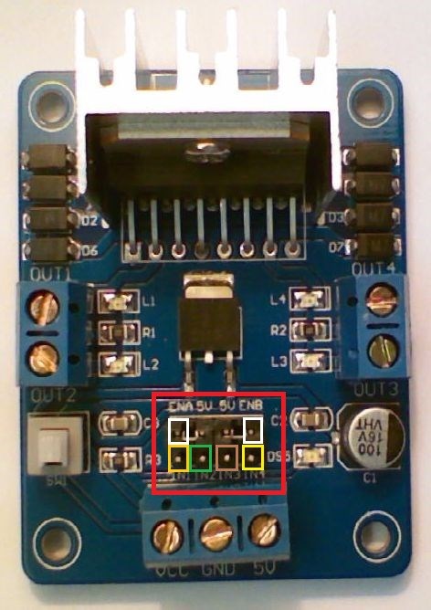
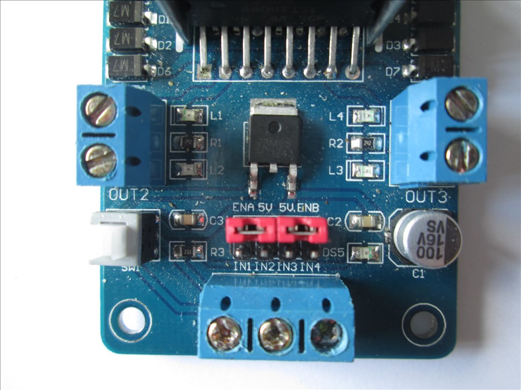
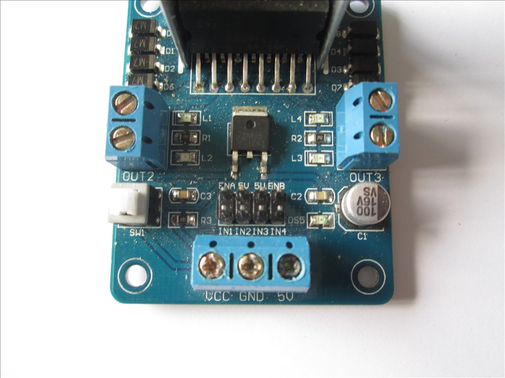
The L298n in it's stock state
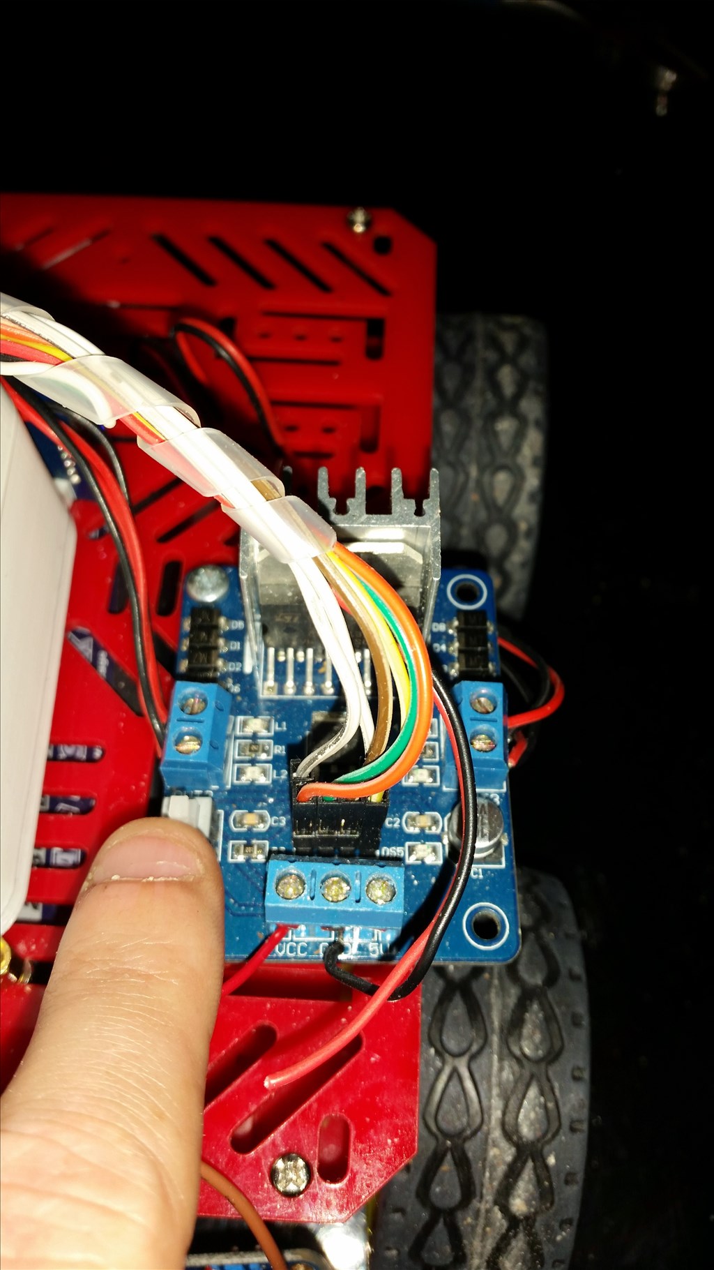
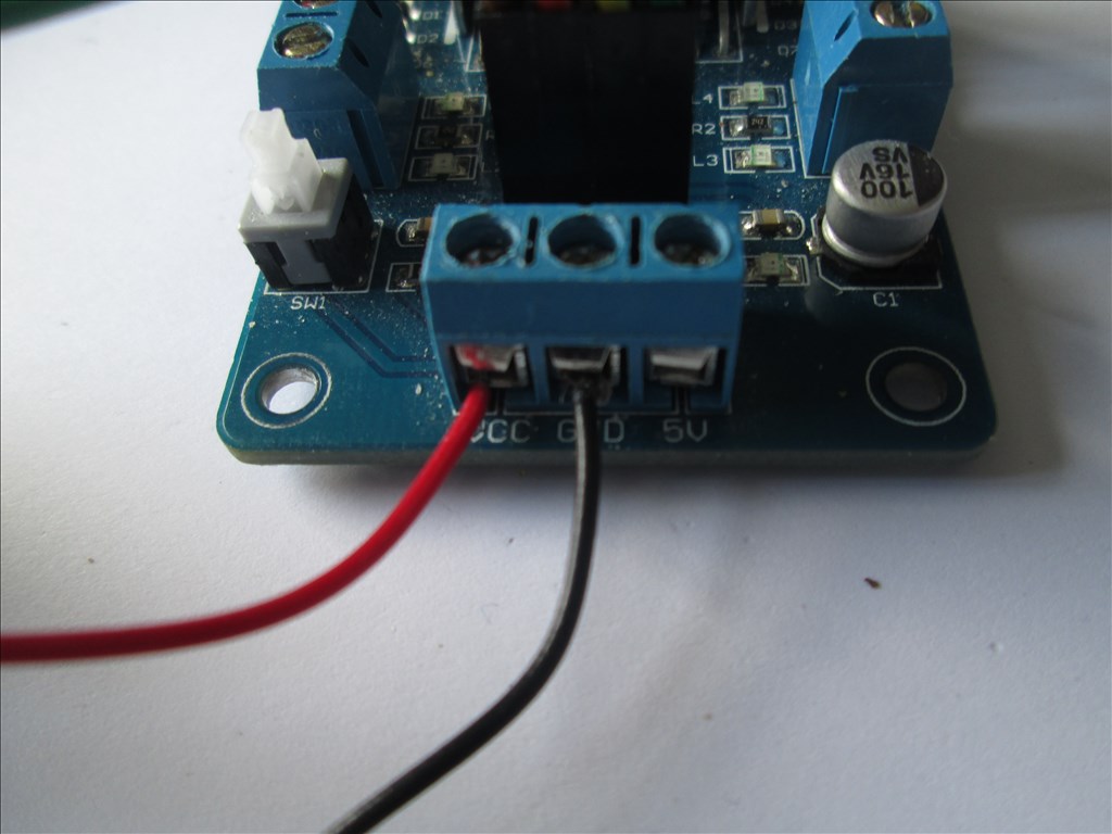
The L298n wired power connections
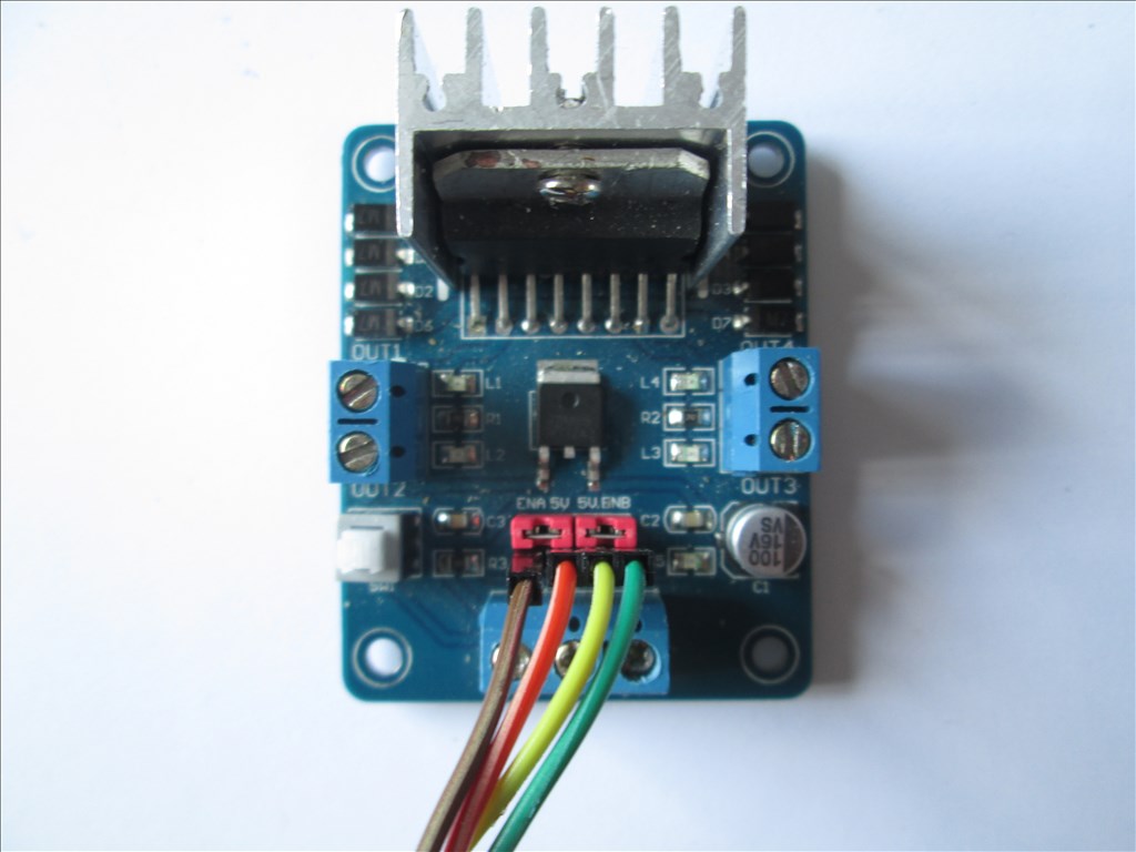
The L298n wired for no speed control
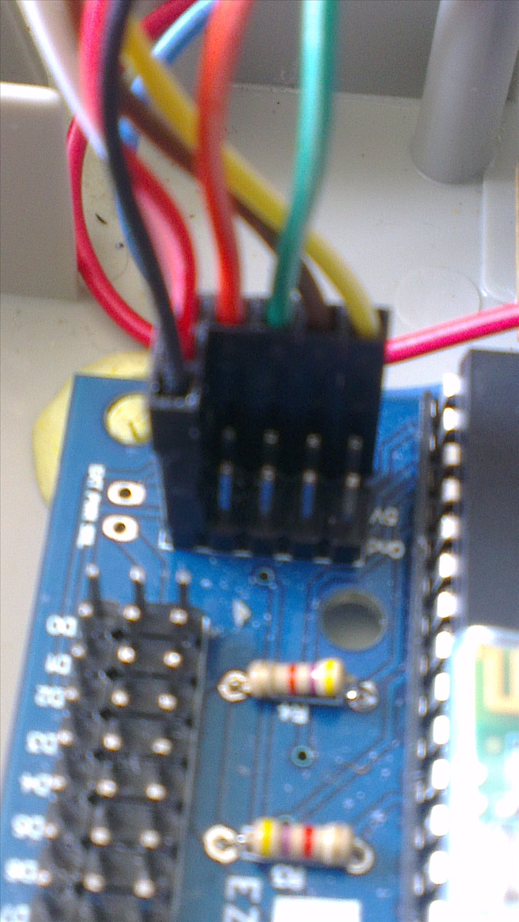
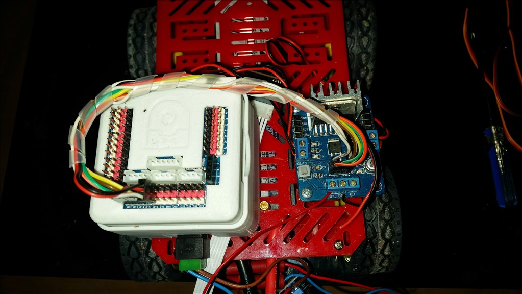
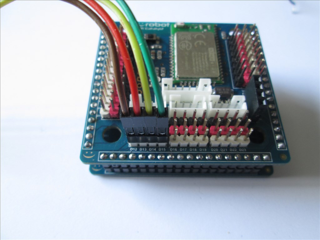
The EZ-B V4 wired for no speed control
The L298n with the jumpers removed
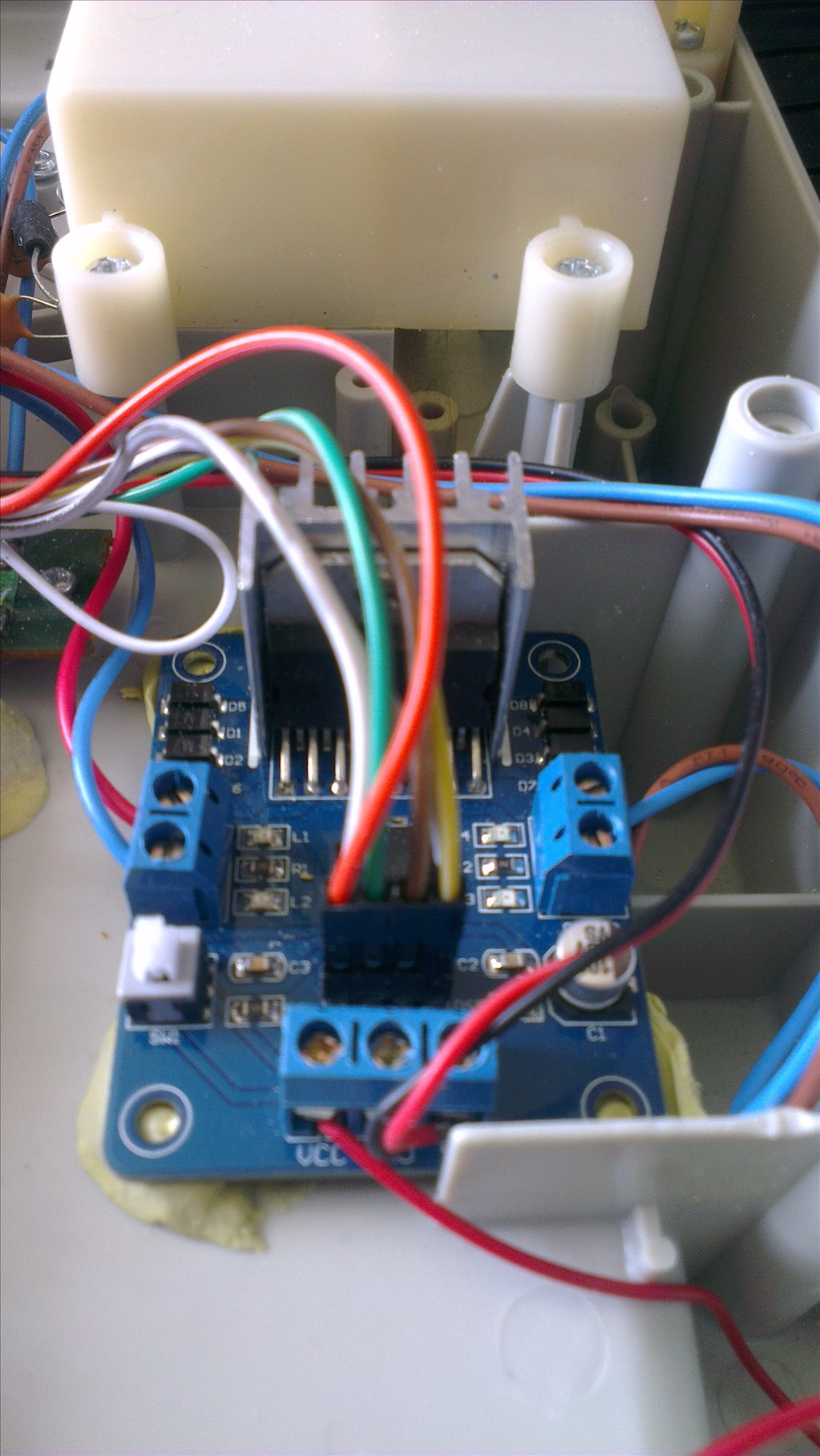
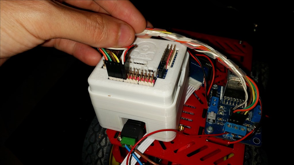
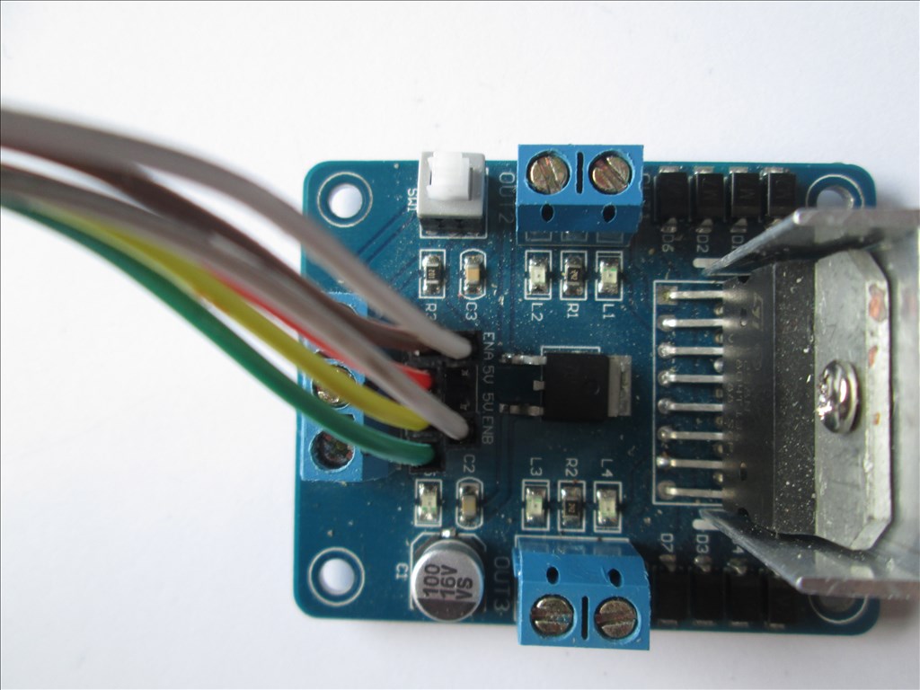
The L298n wired for common speed control (1 PWM adjusts the speed of both channels). White wires is a Y cable, 2 to 1 with the 2 at the L298n end
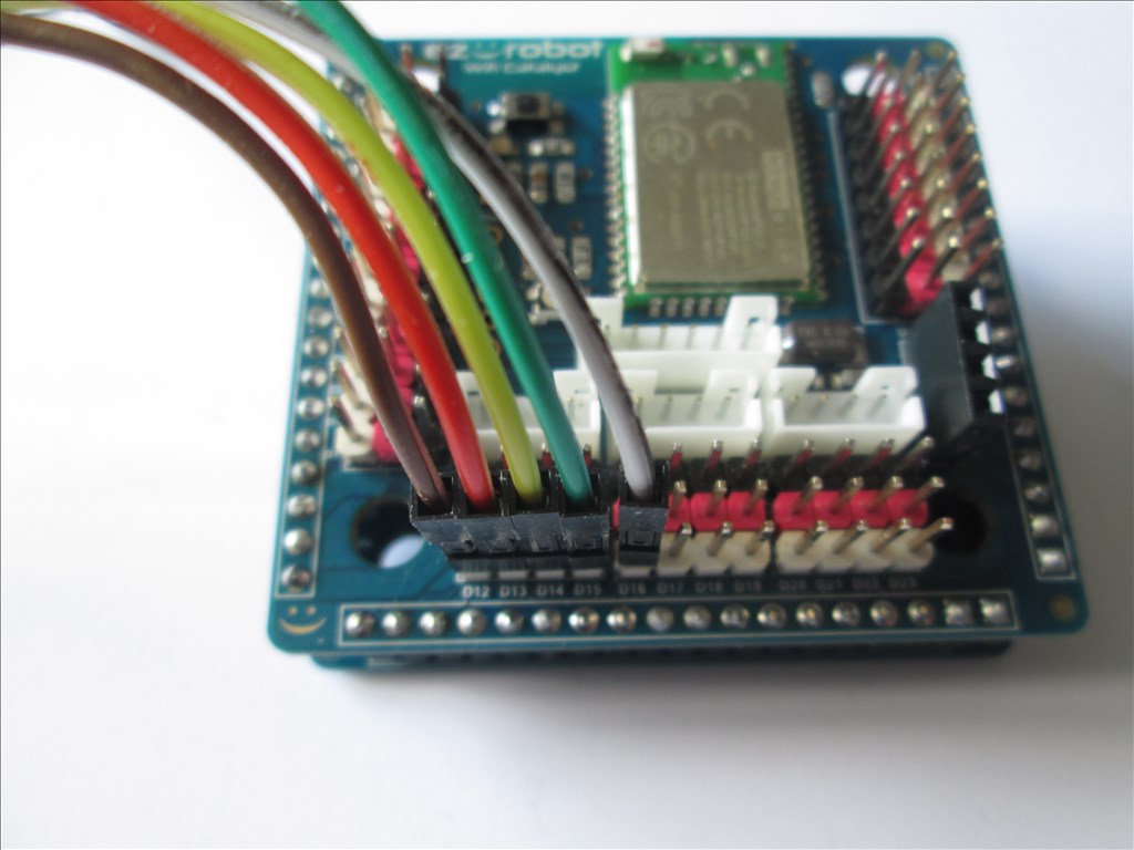
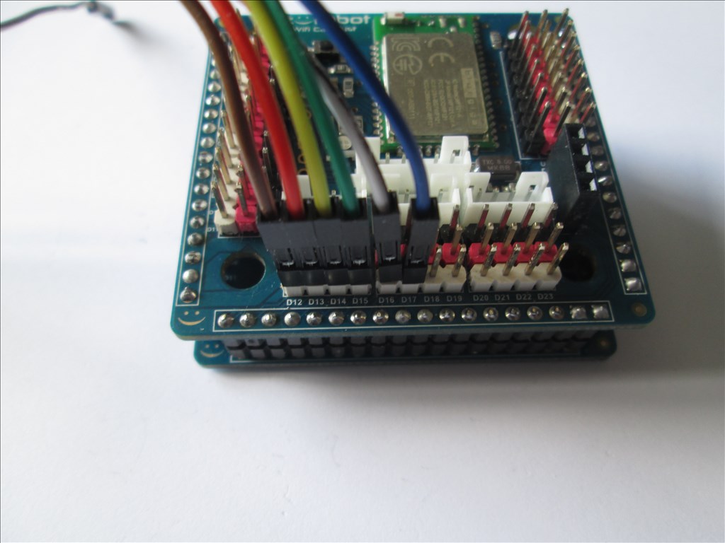
The EZ-B V4 wired for common speed control (1 PWM adjusts the speed of both channels). White wire is a Y cable, 2 to 1 with the 1 at the EZ-B V4 end
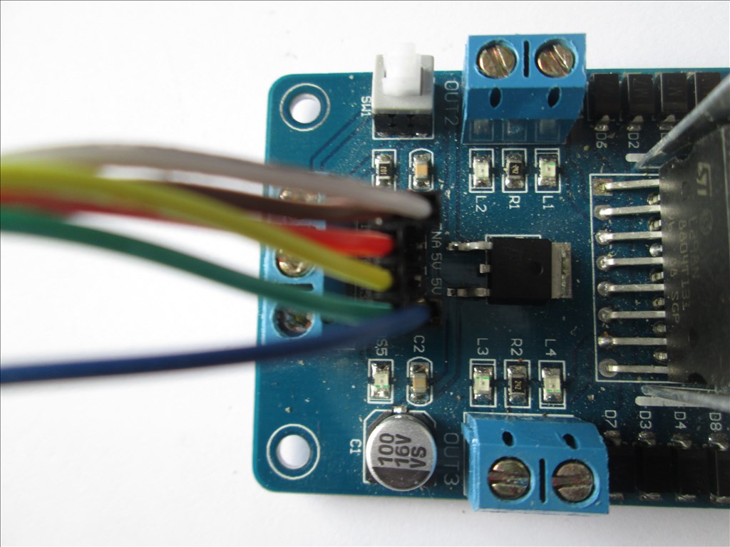
The L298n wired for independent speed control
The EZ-B V4 wired for independent speed control

Independent Speed Control
As in post #1 however with some slight alterations as follows;
Assuming ports D15, D16, D17, D18, D19 & D0 D15 Signal > Left Trigger A (In 1) D16 Signal > Left Trigger B (In 2) D17 Signal > Right Trigger A (In 3) D18 Signal > Right Trigger B (In 4)
D19 VCC > H-Bridge 5V D19 Ground > H-Bridge Ground D19 Signal > H-Bridge ENA D0 Signal > H-Bridge ENB
Connect the positive of the battery to the H-Bridge VCC
Connect motor 1 to the Out 1 and Out 2 terminals Connect motor 2 to the Out 3 and Out 4 terminals
In ARC add a 4 Wire H-Bridge PWM Movement Panel control.
Set up the H-Bridge control as the above D15 to D18 on LTA, LTB, RTA and RTB Set up the Left PWM control to D19 Set up the Right PWM control to D0
This now enables independent speed control for each motor and analogue speed control/movement through the Joystick control.
Frequently Asked Questions
Q: Everything is set up but when I move forwards the robot turns and when I turn the robot moves forwards, what have I done wrong? A: Simply put, one of the two motors is running the wrong way, probably due to the mounting position or polarity. To fix this you have two options;
Q: My robot moves in reverse when it should move forwards and moves forwards when it should move in reverse, what's up with that? A: You have your motor polarities backwards for both motors. You can fix this in one of two ways;
Q: When I turn left the robot moves right, and when I move right the robot moves left, how do I fix it? A: Your left trigger and right triggers are back to front. Again there are two options to fix this;
Q:How hard is it to solder the stuff rather than use a jumper kit? A: That depends on your soldering skills. The In1-In4 and ENA and ENB pins are a 4x2 pin header with 0.1" spacing. It would be like soldering direct to the EZ-B. Chances of bridging pins would be very high. That said, DJ shows it being soldered in the EZ-Robot tutorial for this. So yes, it is possible to solder rather than use jumpers depending on how well you can solder.
Awesome Tutorial Rich, thanks for sharing!
Thanks for the info. How hard is it to solder the stuff rather than use a jumper kit?
That depends on your soldering skills. The In1-In4 and ENA and ENB pins are a 4x2 pin header with 0.1" spacing. It would be like soldering direct to the EZ-B. Chances of bridging pins would be very high.
That said, DJ shows it being soldered in the EZ-Robot tutorial for this.
So yes, it is possible to solder rather than use jumpers depending on how well you can solder.
Great write up Rich!
Great write up. thanks for sharing your knowledge. j
Thanks for the nice comments everyone. And it's a pleasure to do these, it's the whole "give a man a fish/teach a man to build a robot that fishes" thing.
I had a bunch of questions I was going to post about the PWM wiring before I started hooking mine up (going to control two motors on a claw) and this answered them.
Thanks.
Hey Rich, I am currently running ARC Version 2013.07.22.00. I recently updated from version 2013.06.04.00 . Yes I know, it been a while. My personal life had gotten a little ethic, so I had to step away from robotic building for a while. Before the upgrade, My H-bridge was working perfectly fine. I had it set as:
D10 Left trigger A D11 Left trigger B D12 right trigger A D13 right trigger B D14 PWM.
After the upgrade ARC refuse to connect to my ez-b board. It will connect and disconnect, I assume I had an issue with my board. After a few hardwares diagnostic , replacing the fuse etc. I realise it was a compatibility issue from my old save project file to 2013.07.22.00. No biggy, I decided to start from scratch and re-create my project in the latest EZ-B build. Now my Rover refuse to go forward, if it goes forward it will not go reverse. If it goes reverse it will not go forward. I have play around my trigger port setting. Simply refuse to work. I am very anal about saving my projects. I save them as V1.0 V1.0a v1.0b, v2.0 v2.1a , etc, any minuscule change I make, I always make sure I save it into a different version name. But with the latest build. my old project will open, but ezb connection get drop right away and H-bridge set up is a little peculiar. I know we are still in the Beta testing phase no biggy. But have anyone else tested their robot movement forward, reverse, left and right?
I literally just parked my robot up after a quick autonomous roam test and the HBridge panel worked fine.
Do you use the 4 Wire HBriidge control or the 4 Wire HBridge with Speed Control? (I just used the one with speed). You may need to set your left and right speeds although if one direction works and the other doesn't then that wouldn't make sense.
In fact, it doesn't make sense. If it moves forwards it should move reverse.
Add this script.
And this script
Run the first one and see if it moves forwards or if it disconnects. Stop it moving by running the second script.
Reverse the sets in the first for reverse (i.e. 10 off, 11 on, 12 off, 13 on) and see what happens.
extremely weird, I uninstall EZ-b and re-install it and problem fix. Thank you for your help :)
Amazing tutorial.
Many thanks Rich - this helped me a whole lot.
Updated post #1 with V4 connection information
Alternative wiring for a simpler method
The connections on the L298n are simply;
Vcc = Motor Supply Positive Gnd = Motor Supply Ground (ensure this is common if using more than one supply) +5V = Not Connected
In1 = Digital Port Signal (i.e. D8) In2 = Digital Port Signal (i.e. D9) In3 = Digital Port Signal (i.e. D10) In4 = Digital Port Signal (i.e. D11) EnA = Digital Port Signal (i.e. D12)* EnB = Digital Port Signal (i.e. D13)*
No ground or Vcc from the EZ-B to the L298n is required if you have a single source for both EZ-B and L298n or if you have a common ground.
You must make sure you press the switch to enable the on board 5V regulator circuit otherwise it will not operate
Some photos (I'll change them once I get chance to edit and tidy them up but no idea when I'll get the chance so here's the unedited ones).
The L298n in it's stock state
The L298n wired power connections
The L298n wired for no speed control
The EZ-B V4 wired for no speed control
The L298n with the jumpers removed
The L298n wired for common speed control (1 PWM adjusts the speed of both channels). White wires is a Y cable, 2 to 1 with the 2 at the L298n end
The EZ-B V4 wired for common speed control (1 PWM adjusts the speed of both channels). White wire is a Y cable, 2 to 1 with the 1 at the EZ-B V4 end
The L298n wired for independent speed control
The EZ-B V4 wired for independent speed control
Did I read somewhere this controller can control a stepper motor? Thanks. Chris
Yes, info can be found here
Thanks for updating information for ezb v4 controller and h-bridge. I used info to get one pair of motors working on 6 wheel thumper. Work on other pairs tomorrow, one h-bridge down, two more to go.
j
:)
 :)
:)
.... could have just used one 2 x 12 sabertooth motor controller and one port on the ezb.... three H bridges to run the thumper must be an awful rats nest of wires... not to mention using up the majority of digital ports on your ezb.... I guess people still need to do things the hard way....
How I did it. Just upgrading to ezb v4.
J
Richard, good thing there's a ton of ports on EZB to use. looks like there's lot's of ports left over. Most robots wont use them all. People use what they feel comfortable with and can afford and learn. ;)
What can I say, I like being efficient... You can kill mosquitos with a sledge hammer too, but wouldn't a fly swatter make more sense?... Less is more sometimes.... Especially good when tracing problems later....
I agree. It's a fun learning process though! ;)
@Richard R and @Dave Schulpius,
I only have the three h-bridges, I have enjoyed learning how connect lots of wires.
I have not looked into other solution since this was the recommend way with v3 controller.
I have only been at this off and on for the last year and half. One year of waiting for new stuff to arrive.
Took time off while waiting to learn how to do 3D printing. Got that down very well. Have made a lot different things. A few lego bricks and other stuff related to lego's.
Now start to download stl's for ez-robot stuff and make that, while I wait for the kits to arrive.
When I am ready will search for other solutions.
J
:D
 ;)
;)
What is the +5v terminal used for on the L298? confused
If you don't want to use the on board regulator you can supply it with +5V from other means. On the V3 I don't use the L298n H-Bridge's regulator so I take a Vcc from a digital port to the L298n.
On the V4, since it's not regulated, use of the on board regulator is required - press the switch on the l298n to enable it. Some L298n H-Bridges don't have an on board regulator so these will need a +5V to the +5V terminal.
Thanks Rich. Btw, I could still do with your help on this topic, specifically post #13. I've followed your great tutorial, but I just need a bit more help finishing off if that's cool.
Cheers, Steve. (--EDIT--)
Forget the above post. Completely forgot I had this question answered in another thread. It's been a busy week with hospital appointments ect. Sorry about that eyeroll
I just received a H-bridge. Super fast delivery. This tutorial will be a great help ! Thanks for posting
Cheers Johan
I heard that H bridges can be used as brakes.
I am trying to set up an off-brake for every single servo in my robot. Lets assume I will be using 24 servos so I need a cheap solution that is tiny.
So far I have tried using a Y splitter from the PWM cable that connects both a servo and a tiny RC Switch to a tiny Pull Solenoid. What I hope will happen is that the RC switch will trigger the pull solenoid whenever there is any pulse at all. That would pull the brake away instantly whenever the servo moves and a spring would force the brakes on whenever the servo receives no signal. So by default, the brakes are always on. When the servo wants to move, the brake releases.
Unfortunately, all the RC switches have only activated when the servo rotates clockwise more than 50% of the way. I want it to activate when there is any pulse at all. Would an H bridge help, are there RC switches specific to my needs or is there a better solution?
It would be great if someone could answer the questions in the description of this video if you have a YouTube account for commenting. It will help all of you immensely as cybernetic engineers.Thanks
Search TIP 122 circuit in the search area.
I'm feeling really stupid. I bought the l298n H-bridge and have it hooked up to the exact digital ports as you display. The only difference is that I am trying to drive a 12VDC motor so I have a 12VDC supply connected to the Vcc on the H-bridge. But when I press any of the arrow keys nothing happens. No voltage on the out pins of the H-bridge. What could be the problem? Yes, I have the pushbutton pressed and the red led is lit. I don't think I need to write any script?
@Castlephelps.
Are you using 2 different power supplies, one for the EZ-B, and one for the motors? If so, do you have a common ground wire from your 12v motors supply ground terminal to an EZ-B ground pin or the EZ-B's power supply ground?
@Castlehelps, you didn't mention if you had configured the HBridge to use the specified ports. Can you clarify that you indeed pressed the configure button on the HBridge and configured the correct ports?
Also, which HBridge control are you using? There are both the HBridge and HBridge PWM - each requires a different wiring configuration.
Also, are you connected to the EZ-B v4 during this test? This is done by connecting to the WiFi of the EZ-B v4 and pressing the Connect button in ARC.
Thanks! I have separate power supplies / the 12vdc is powering the h-bridge and a battery pack powers the EZ-B. So I need to wire a ground wire between the EZ-B and the ground on the H-bridge?
For DJ / I have configured the ports on the EZ-B in both configurations but no joy. Yes the computer is connected to the EZ-B.
Castle
Yep, that should be your problem. Run a ground wire between the two power supplies or the two devices.
Yes @castlephelps the ground connection from both supplies will have to be together somewhere, either on the EZ-B or otherwise. This is because both power circuits need to have the same negative reference or one value will be "floating" compared to the other value.
Also keep in mind that if you are using the H-bridge with PWM control you will need to either have an initialization script run to initiate the PWM lines (see Roli example) or you will have to move the PWM sliders once to initiate them manually.
Quick question, are you using DC motors to test with or are you still driving a stepper motor? If you are using a stepper you can't use the h-bridge controls you need a script to drive the step sequence.
Thanks! I gave up on the steppers - I couldn't get them to move either even with the code... now just a DC motor.
The ground wire trick I will be testing as soon as I get home from this Christmas party!
Castle
Yay! It works! The grounding idea was part of it and I had the PWM assigned to the wrong port...duh!
Now what I need to do is separate the two motors so that one motor does forward / reverse and the other does left and right. The reason is that I am driving a gantry for my robotic arm and one motor will move the gantry East and West and the other motor is mounted on the trolley of the gantry and will be moving North and South. I guess I just need to build a truth table that is different but I don't know how to do that. I'm so excited that it is driving my motors!
A second question is: How do I drive a motor that draws 25 Amps DC both forward and reverse As super H-bridge or ?
Castle
Glad you got the L298 sorted now.
In regards to the 25amp motors question, Dimention engineering is a popular choice. There is a Sabertooth 2x25 (not the R/C one) that delivers 25 amps per channel which can leak up to 50 amp per channel. But as you say it's only for one motor, the SyRen 25 motor driver with 45 amp peak current might be a better solution for you, although you may want to consider getting something that can handle slightly higher amperage, like the 2x32 or SyRen 50, if there's a chance you motor could draw more than 25 amps for more than a few seconds.
www.dimensionengineering.com
I believe that the SyRen 50 is the solution!
Now - if I have six motors that I want to run with H-bridges how do I do that? I am unable to add a second h-bridge to my Project in ARC?
Sorry / what movement control would I use with the SyRen 50?
EZ Robot only allows one movement control per project. You would have to write scripts to operate more H-bridges.
The SyRen is controlled by Simple Serial commands through EZB's Uart port. Just like the Sabertooth. I haven't tried it but I think you may be able to use the Sabertooth control within ARC with the SyRen. They both are made by DE but the SyRen is the low budget model. EDIT: I think the biggest difference is that the SyRen will only drive one motor and the Sabertooth will drive two.
Are you looking for position and speed control? If so you'll also need one of DE's Kangaroo X2 daughter boards along with the SyRen.
Am I going to have a problem hooking up 1 SyRen and several sabertooth's to one EZ-B? Can I use scripting to provide positional feedback from saber tooth or do I need to have a kangaroo for each? And what about using positional feedback with h-bridges? I really do need to provide DC motor control for seven or eight motors with positional Feedback.
You could also use a bunch of low cost BTS7960B 43A Motor Drivers (from ebay) to drive your 25A requirement but yeah you would still have to write scripts to control each one independently.
The H-bridge Movement Panel is usually used for the lower locomotion end of the robot. Driving the robot around. @castlephelps are you using DC motors for robot appendages or for driving it? Or both?
Positional feedback can be used with H-bridges but you usually don't see both systems tied together. Optical encoders and a encoder wheel can be applied to just about any motor to give it positional feedback. A Large RC servo motor could also be used as an alternate solution.
So, DJ, why only one Movement Panel per project / Are you just assuming everyone builds robots that only roll on the floor? But seriously, it seems that you should be able to support many h-bridges, even across multiple EZ-Bs...
Well, you actually don't even need a movement panel. However one does come in handy for moving the wheels of a robot so you can roll it around the house or yard. I don't use a Movement Panel in my project and I'm moving 7 DC motors in my robot. All motors are moving arms, waist and radar sweep motors. He's not going to be moving around the house so I'm not going to be using a movement panel. The scripts I have move these motors to the positions and speeds I want. The scripts respond to voice recognition or personalty generation or sensor readings. I plan to add a joystick or tablet control soon to control the arms of the robot.
As far as the Kangaroo X2 and either the Sabertooth or SyRen; Yes, you'll need one Kangaroo per Sabertooth or SyRen unit. You can control 2 motors with one Sabertooth and a Kangaroo or one motor with one SyRen and a Kangaroo X2. LIke Jermie mentioned you'll also have to add a feedback device like an encoder or potentiometer. These are so the motor controller and EZB knows where the motor is when needed and how fact it's going. ;)
Wow! That is the information I really have been looking for! Perhaps you would be willing to hate some of you scripting knowledge with me as I go along?
I ordered the SyRen today and it is being delivered tomorrow / I will get the kangaroo ordered tomorrow. My SyRen will be controlling a hydraulic pump for my arm and I have it fitted with a Spectra Symbol linear softPot potentiometer / so I will need some help connecting those pieces together and then writing test scripts.
Thank you very much, Castle
Dave,
I am planning to do everything with voice control so what you have done and what I am planning are very similar. My first task is going to be the control of an arm that extends 6 feet using a rack and pinion, a dc motor and a 10 turn pot for feed back. I have attached a video of the initial testing retracting with a 70 lb lead weight on it.
So when I get the Sabertooth tomorrrow how do I connect it to the EZ-B and how do I address it in ARC?
Thanks again, Castle
Trying to hookup a Sabertooth 2x25v2 to 2 motors (Wheelchair motors). Has anyone done this before? Not sure what DIP switch setting to use on Sabertooth or how one might configure for multi control for joystick. I have been successful with H-Bridge on smaller projects before but this is a little different. Thanks!
Jackphiiips, Did you read the documentation on this controller? DE has a very clear manual with steps on how to setup and do what you're wanting. They also have a dip switch wizard to assist you. Here's a couple links to follow that will get you going. If you've already read through all this then let us know what you've tried and where you are having trouble:
Look under the documentation section down the page for lots of links to help:
www.dimensionengineering.com/products/sabertooth2x25
Other good links on that page: Manual
Did Switch Wizard
@castlephelps I guess I should have been clearer. Many H-bridges can be supported by ARC. Approximately 8 single H-bridges or 4 Dual H-bridges via scripting. It's true that there is only one H-Bridge Movement Panel supported per project.
You see, the H-Bridge Movement Panel is designed for a Dual H-Bridge system where 2 motors have to work in tandem (both move at the same time). This is ideal for Robot drive systems but not ideal for Robot Arms and legs. If you have multiple motors you need to use with the drive system you'll likely just want to use a higher rated H-Bridge and connect the motors in parallel on each H-Bridge channel. It is extremely rare that a robot would ever need 2 or more independent drive systems so that is why only one exists in ARC.
If you are using single H-bridges, for robot arms let's say, you likely don't want to use a control that puts 2 motors in tandem but rather you'll want to have them operate independently from each other.
A single H-bridge control is likely what you are looking for and at the moment it doesn't seem to exist in ARC (besides the continuous rotation servo control). I think this is a great idea for a plug-in......hint hint Anyone up for the challenge?
Hi Dave,
Thanks for links and the help.
I have used the H-Bridge before with success and now I need to use the Sabertooth for 2 wheel chair motors.
I have been trying to use the Sabertooth serial with no success. I believe I need 2 outputs to control motors separately.
I need to be able use both motors separately so I can make turns with the 2 motors.
I was able to do this easily with H-Bridge.
Sabretooth seems way to go with these motor, I may run at 24 volts in future.
Any suggestions?
Thanks.
The sabertooth is a breeze to use compared to an H-bridge... 2 wire connection, simple serial commands... They are way expensive but I use them exclusively in my projects... The H-bridge is great for small robot projects...
Hi Richard,
In what way is it a breeze?
How did you connect to EZ?
By that I mean what EZ control did or are you using?
Thanks.
You connect it to any of the ports... Just 2 wires... ground and signal... all ports can send serial commands on the V4... You can also use the UART ports as well... Sabertooth set up for 38400 buad (Dave gave you the links to the manual)
You do not connect the red power from EZ D0?
No... that is for a bec.... You just need signal and ground only... From the ezb... Ground to 0V and signal to S1 on the sabertooth...
Looks like I need to do a sabertooth tutorial.... :)
Ok thanks. Still get nothing though what you wrote makes sense. By connecting red EZ to positive on controller could I have damaged something?
Still not working yet?
Have you set the dip switches for simple serial at 38400 baud?
Yes. I t seems to be ok now. I rebooted EZ and power is working.
Thank you very, very much.
Video may be a good idea or instruction at least.
Thanks again.
Yay! My Sabertooth is coming today, not sure when the Kangaroo will arrive but a tutorial and a video would be incredible for us newbies going this direction. From everything I have read - this combination is the Way to Go! Thanks Richard - hopefully you will have a tutorial for us shortly :-)
Castle
There are a few videos of the Kangaroo/Sabertooth boards on Youtube. Check them out.
Castle, When using a Kangaroo with the Sabertooth your dip switches will be set completely different then what RR shows.
There is very little on the net about the Kangaroo. What I found was very little use. Your best bet is asking or searching here as it seems there are is a lot of knowledge on this forum about it. DE has a good Tech Support person but she is real slow do to overwork load. Make sure you read all the documents on the controllers your getting from DE's web site. I posted links in your other thread you started about all this. Here's one that I made that show somewhat how to do an auto tune:
BTW, did you see the posts on your other thread regarding this subject? You may want to use that thread from now on. This is kinda off subject from what we are talking about. :)
Thanks Dave - switching to Multiple Motors
Hello. Newbie to EZ-B here. Not new to electronics/robotics.
I am unable to get my motors to react. I am using two power supplies, so I wanted to make sure that connecting one of the ground pins on the top of the EZ-B to the ground of the power input of the board is sufficient.
If it is, I do not know why things aren't working.
I have the PWM bridge. I have LTA->D8, LTB->D9, LPWM->D12,RTA->D10,RTB->D11,RPWM->D13.
I have hooked the motor battery directly to the motors to confirm they are working.
What should I do first to troubleshoot this?
Thanks
ground to a ground pin on the EZ-B should be fine.
Some LN298's seem to have the 5v button wired backwards, so even though this tutorial says it should be in the down position, try it in the up position.
Alan
That was it. I put the button in the up position, the 5V LED lit, and the motors started responding to the controls.
Thank you.
I really appreciated Rich's tutorial on H Bridge configuration and wiring to the EZ B. I have several of the following 12v Dual Channel DC Motor Drive Module H Bridge with PWM Input on hand, but the input on them is different than the H Bridge Rich used. I admit that I am new to using an H Bridge as most of my past robot builds were glorified R/C puppets using an R/C PWM microcontroller.
That being said, I am hoping someone can give me some direction on the pin out on this H Bridge and how to interface it with the EZ B.
1 VCC Isolated positive power input, compatible with 3.3V, 5V power supply 2 PWM1 M1 channel duty cycle modulation input, high-speed isolation, bandwidth 50MHz 3 INA1 M1 Channel Control Logic Input A. 4 INB1 M1 Channel Control Logic Input B. 5 GND Isolated power input 6 VCC Isolated positive power input, compatible with 3.3V, 5V power supply 7 PWM2 M2 channel duty cycle modulation input, high-speed isolation, bandwidth 50MHz 8 INA2 M2 channel control logic input A. 9 INB2 M2 channel control logic input B. X. GND Isolated power input
purple
your qr code says ez robot.you chould never post a qr code.everybody can read , them ,scan them.
that hbridge connects the same way the ezrobot hbridge does. Follow the ezrobot hbridge connection diagram and you’re good to go.
Thank you DJ. My HBridge has 10 pins however. Rich's example has an HBridge with 8 pins. What pair do I ignore? I guess a better question is if there is a diagram that cross-maps the pins on this type of HBridge to the connections on an 8 pin HBridge or to the EZB?
It's the same wiring, exactly.... except the 3-5v dc connection. That can come from the power of an ADC port. Here's wiring from the ez-robot HBridge PWM control: https://synthiam.com/Support?id=192
DC3-5 -> EZ-B ADC 0 RED (power) PWM1 -> D4 INA1 -> D1 INB1 -> D0
PWM2 -> D5 INA2 -> D2 INB2 -> D3
And the motors... M1A -> motor M1B -> motor
M2A -> motor M2B -> motor
And the power for the motors P- -> your battery negative P+ -> your battery positive
Okay! It takes me awhile, but I will eventually get there.
In an effort to understand what you were conveying, and understand Rich's lesson plan, I had to break things down visually for myself. I produced the diagrams below to help me walk through the fundamentals. What got me confused was connecting B1 to D0 and A1 to D1 instead of A1 to D0 and B1 to D1. I still don't understand this, but eventually will.
Please let me know if I correctly illustrated the wiring between the EZ-B and the H-Bridge I am trying to use. I'm assuming that I connect both V and G pins on the H-Bridge to the Red Power and Black Neutral on the EZ-B (D0).
Thank you DJ for taking time to guide me.
-Sean
1 VCC Isolated positive power input, compatible with 3.3V, 5V power supply 2 PWM1 M1 channel duty cycle modulation input, high-speed isolation, bandwidth 50MHz 3 INA1 M1 Channel Control Logic Input A. 4 INB1 M1 Channel Control Logic Input B. 5 GND Isolated power input 6 VCC Isolated positive power input, compatible with 3.3V, 5V power supply 7 PWM2 M2 channel duty cycle modulation input, high-speed isolation, bandwidth 50MHz 8 INA2 M2 channel control logic input A. 9 INB2 M2 channel control logic input B. X. GND Isolated power input
@Dj, let me know if I got the H-Bridge right. I am trying to document everything while I wait for my EZ-B to come in!
Also check out my post on WowWee's CHiP. I detailed out a lot of info!
load ARC on your windows pc
connect to the ezb via WiFi
press the connect button on ARC
add the hbridge pwm Control to your project. The instructions to add the control to your project are on the top of this page: https://synthiam.com/Support?id=192
press the config button on the hbridge pwm Control that you just added to the project
connect the DC3-5 -> EZ-B ADC 0 RED (power)
connect the PWM1 -> ezb D4
connect the INA1 -> ezb D1
connect the INB1 -> ezb D0
connect the PWM2 -> ezb D5
connect INA2 -> ezb D2
connect INB2 -> D3
And the motors... M1A -> motor M1B -> motor
M2A -> motor M2B -> motor
And the power for the motors P- -> your battery negative P+ -> your battery positive
Ok cool. I will do this as soon as my EZ-B comes in.