Hey guys.
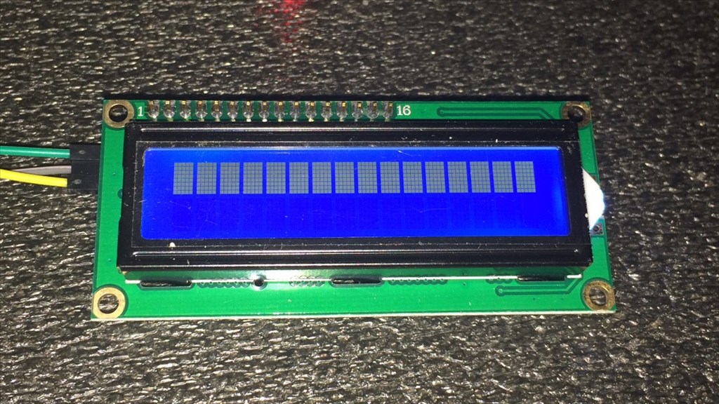
I'm having a little trouble with an LCD display I recently purchased. I have read through some of the posts on the forum to help me get this going, but I need a little more help. I have it connected to D12 going through a 5v regulator. Ground to ground, Vcc to Vcc, and SDA (which I believe to be RX) to a signal pin. It lights up but when I try SendSerial(d12, 9600, "Hello" ) nothing happens. I have also tried a different port and changed baud rates, no change.
Now I believe this is a serial (what I was after) and i2c compatable so it should work. I havn't found a data sheet for it yet but here's a link to it, if it helps. Any ideas what's going wrong, or even if this thing is compatable with the v4? I hope some one can help as I would love to get this working.
Thanks in advance.

Ah the good old LCD display and serial commands.
This is what helped me understand how frustrating datasheets can be!
While it uses I2C rather than serial, this topic should help you.
It's not as simple as sending text for it to appear. You need to let it know you are sending text, you need to set cursor positions etc.
I'm sure I have a 1602 backpack on an LCD somewhere which I have covered, and I am sure the commands were either the same or very similar to those in the topic I linked to (just replace the I2CWrite for the SendSerial command).
Here is another topic worth reading through.
Try these commands, I can't guarantee they will work but I just found the list :)
And possibly try this script;
Haha, those were the exact two threads I was referring to. I'll give the script above a try and report back in a bit.
@Rich.
Tried the script, but it comes up with an error...
Are you sure that's a uart/serial lcd? The ports read i2c labels...
If it's i2c, like the labels display... You're in for a treat. Those cheap screens have zero documentation and to my knowledge, no one has gotten one to work yet
My one is both serial and I2C (there is a jumper on it to change it) however I am unsure if that was the Digole or the cheapo one, I'll check when I am home, I have a feeling DJ is correct and I threw the "El Cheapo 1602" in the bin as it was useless.
I'll check in about an hour, just need to get home and check it out.
Edit: No need to wait, I found my topic I made... here. The one I threw out was the "El Cheapo 1602" as no commands were known nor could I find any reference to them.
Don't immediately throw it out, I'll see what I can dig up on it and decipher.
No problem. Sounds like I have been bitten by the "wrong description" bug then. I did contact the seller to confirm if it was both i2c and serial, which they did. Oh well. Thanks guys.
@Steve, this may not be relevant at all (especially if your LCD is I2C and not serial) but try putting non number commands in quotes as below... It should get rid of the missing sting quote error at least...
@Richard picked up on an error That's the syntax change which happened between me writing that and now.
However, note my edit on my previous post.
@Richard.
I just gave it a try. Got rid of the error messages, but still no dice. ;(
Thanks anyway.
Okay Rich. I'll hang on to it for a bit longer then.
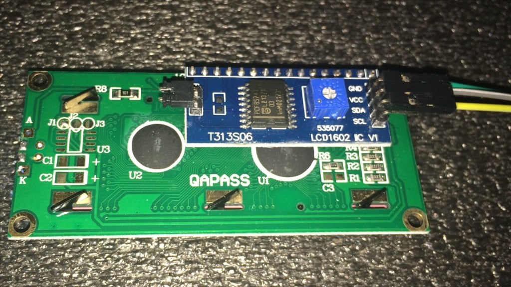
Question, what is that jumper for on the back of the display?
It says it's for the LED backlight.
Ah, ok... thanks
If it is i2c, you will need a data sheet. Also pull up resistors for the data and clock line.
It looks like that jumper is for the led backlight
@DJ.
I've just been looking for a data sheet but havn't come across one yet, only some Arduino code which I know nothing about. I really want to steer clear from i2c anyway as when I get my new v4 at the end of the month, the i2c ports will all be used with something else. Unless Rich or someone else can come up with anything ill look at getting another display I can use on digital ports.
Thanks anyway. :)
If you want to steer away with I2c, then you will have to get another lcd the labels on the connector of that lcd are i2c. That is an i2c lcd. Sometimes on eBay they call them i2c serial. This is because i2c is a "serial" protocol, it's just not the serial uart that you're thinking of.
You can start by adding pull-ups to the data and clock lines. Then review the arduino code and see what you can get working eith i2cwrite()
I'm pretty sure it's I2C not Serial. The display itself may be classed as serial but the backpack that controls it is certainly I2C with those labels.
Problem 1: What's the I2C Address? Problem 2: What are the I2C commands for various tasks?
Searching the interweb it looks like the I2C address for this is 0x27 however that is not certain. Does anything on it say an I2C address or does it have a number like 0x27 stamped on it?
It looks similar to this one which is 0x27 (apparently!)
Unfortunately if it is not on 0x27 and we think it is then trying commands is going to be redundant.
However, let's assume 0x27 is correct. Now we need to know commands for the little blighter...
There are Arduino libraries for these, the LiquidCrystal library for example. Unfortunately I still do not understand enough about Arduino to be able to pick the library apart and find what needs to be sent to the I2C backpack, perhaps someone who has come from Arduino or can understand them can help on that?
Alternately, grab one of these and swap the nasty, unknown backpack for one which we know works or better still a Devantec LCD05-25-Image-Card from www.robot-electonics.co.uk (however they come in packs of 25, you may find single boards on ebay or could try asking robot electronics if they do them individually)
Looks like DJ beat me there :)
I2C can be chained, you are not limited to only 3 on the V4, you can chain up to 255 (I believe). I had 6 or so I2C devices on Melvin which come from the single I2C port on the V3.
I preferred I2C for two reasons...
If you want a good LCD which is UART serial I recommend Digole ones, they are pretty cheap and documented, I have written a few posts about them and have a lot of notes on them. Also Devantech are great LCDs however a little more pricey but very well documented.
So this is i2c only then. I'll inform the seller of that as he clearly misinformed me when he said it was both. Oh well, live and learn.
I thought the i2c ports may have been serial ports, but clarification is good so thanks for clearing that up. :)
The display I have doesn't have an address stamped anywhere on it, but I've pretty much given up on it now.
Rich, the robot electronics link didn't work, but found the site and had a look. Could you confirm if these displays are what I'm looking for before I order one? The one in the pic below is what I'm looking at.
Cheers.
Thats the one. I use the 4 line one in Melvin and couldn't be happier. Tony (@toymaker) recommended them to me so they must be good They are a little expensivr but worth the extra as they are easy to use.
Great, thanks for confirming. That'll teach me to go cheap :P. Yeah don't mind paying the extra beer tokens for something that's tested and recommended. I'll stick with the 2 line due to space restraints, but the 4 line is tempting.
Thanks for all of your assistance Rich, Richard and Dj. I've come away from this with a bit more knowledge (which is always a good thing) of using LCD displays with the EZ-B and ended up with a good resolution.
Thanks again guys. :)
Steve.
I learned the exact same way! I think we have all learned that lesson one way or another.
Hey @Steve G I figured I'd chime in and mention that I was working with that exact I2C LCD with the ez-bv4 yesterday. I had it responding to simple commands like turning the backlight on and blinking the cursor but I haven't had a chance to go too far with it.
I can confirm that the 0x27 I2C address does work but I would recommend a 1Kohm pullup on both the SDA and SCL lines if you'd like to use the LCD at a little bit of a distance away from the ez-b.
I may look into getting it working, but it will have to be on my own time. Are others interested in using these?
Thanks for responding Jeremie. I'm going to go with Rich's suggestion and recommendation of a new display, but I think it would be worth looking in to getting these cheapo displays to work if your willing to continue, as they are, Well... cheap, so others may be interested.
One question for you though, or for anyone else. Not being well versed in electronic circuits, can I ask, what does the pull up resistor do, especially in regards to the LCD's we're talking about? I did do a quick Google search but I'm still none the wiser.
Also, the displays that have been mention so far are 5v. Does anything need to be added to these when using the 3.3v i2c (unless that's what the pull ups are for)?
I can also confirm that the LCD does work with 3.3VDC, nothing else needed besides the pullups.
Pullup resistors are used to overcome line capacitance on an I2C communication bus which can operate up to 400pF. If you look at I2C signals with an oscilloscope you can see that the clock and data signals usually look like a shark fin (capacitive effect) but when you add pullups it makes those signals "squarer" and easier to be read by the application processor. Those signals sometimes don't even reach the voltage level needed (3.3V) and thus get "pulled up" by the resistors to a 3.3V level in order to make a solid "High" signal.
The further away you get away from the application processor the stronger (lower resistance value) you'll need.
Ok, I'm kinda with you and it's making a little bit more scense to me now. Thanks for explaining it Jeremie. :)
Lol, sorry for the geek speak. I think that if you google some I2C signal screenshots it might make more sense :)
Hey, no worries. I enjoy a bit of geek speak as much as the next, er... geek. :P
Thanks again.
Okay. So I ordered a new display from robot electronics and it arrived this morning. I connected it up to a digital port using a 5v regulator (battery is a 7.4 LiPo), powered it up and... Nothing. It didn't light up at all. The battery is fully charged, EZ-B connected, and It is wired correctly following the tech document as pictured below.
It's getting power because if I hold it to my ear, I can hear a very faint high pitch electrical hum. It tried a couple of scripts, but nothing.
Any ideas?
Steve G, its not working on I2C as you have it set on serial - remove the black jumper on the 2 pin (Mode) header then it will be set to I2C.
Here is my original thread on using these displays.
synthiam.com/Community/Questions/3295
Hope this helps.
Tony
@Tony... I think Steve is actually trying to use serial, not I2C....
Richard R, I missed that, I saw Jeremie was talking about I2C on the previous page so I thought is was I2C. With I2C Steve G would have needed 4 connections (SDA,SCL,+5,GND) to make it work, so I guess that should have given me a clue!
I'll dig out my notes on this LCD shortly, in the mean time.
Pull the wires off of the pins a little to expose part of the pin, or put the wires on so that the small window in the connector showing the metal part is accessible. Then test to make sure you have +5V there.
Here is an edited script I use in Melvin. Note, I am battling a cold so my head is full of goo and my editing may not be perfect...
If memory serves me correctly the LCD has a welcome message when powered on so the above script shouldn't really be required. I would check to make sure that there are +5V at the LCD first and that the supply can provide enough current for the display.
You are right Rich, the LCD05 does have a welcome message that can be seen clearly on the green display version (without backlight), but on the blue version it is quite faint until the backlight is illuminated.
Rich thats great i hear that you didnot know any thing about robotics but you learnt many things one help can you teach me about codings in programing because its my computer science project blush blush blush
Will you a teacher for me but no fees :)
:)
Thanks for the replies guys.
No worries Tony. Yeah it is serial I'm trying to connect to. I'll check out your tutorial out in a bit. I still havn't got my multimeter that I lent out back yet (really missing it now) but WHEN I get it back I will test it. Although the two ports I tried does power a servo and LED.
I would like to try it on i2c, but the v4 I'm using for testing is inside K-9, and the port is quite difficult to get to at the mo.
I feel your pain Rich. I've been battling a rotten cold since Thursday, so robotics has taken a back seat until my head clears up, but wanted to try the display as it arrived so quickly. tired
So I finally got hold of my multimeter. I did what Rich suggested and it turns out the 1 amp 5v regulator was not suppling enough power.
I decided to dig K9's EZ-B out and connect the LCD in to an i2c port. Partial success. I ran Tony's script from his tutorial, and the screen light up, but no text. It wasn't until I had a closer look then I could see there actually was text being displayed, just very very faint and only viewable at an angle. The first pic below is looking at the screen face on, the second at an angle.
So what am I missing? confused
Set up the contrast.
My init script from Melvin was this;
Steve G, I think you may need to adjust the contrast set byte from memory I think its command 30.
Tony
Great, thanks guys. I'll give that a try tomorrow and report back.
Cheers.
Steve G, what you could do (as the v4 is embedded in your robot) is to bring an I2C cable from the v4 header socket out to the side of K9 - this way you could plug the LCD05 for debug or displays etc very simply without disturbing the internals.
Tony
UPDATE.
Thanks for the advice Tony :). I managed to remove the EZ-B enough to connect an i2c cable without too much bother.
So, after testing he display again using the Melvin script Rich supplied, here are the results...
As you can see, it is an improvement but still too dim to be read properly. I played about changing the last two values which did make subtle differences to the backlight brightness and contrast, but not enough.
Is there a list somewhere that explanes what the number values do? For example...
The first 0 and 0xC6 are board number and i2C device address, but don't know about the rest. Understanding this would help me out heaps.
Steve G, this is what Rich's code line means
0xc6 = I2C address for the LCD05 0 = write to command register 1 = set cursor to home position (top left) 4 = hide cursor 12 = clear screen 19 = backlight on 30 = contrast set ** 255 this is the value of contrast set - try lower value here 31 = brightness set ** 80 this is the value of brightness set - try different value
Hope this helps
Tony
Taken from http://www.robot-electronics.co.uk/htm/Lcd05tech.htm
Note: Serial commands are pretty much the same.
In the example in your post (0,0xC6,0,1,4,12,19,30,255,31,80) it's as follows;
0 = Board Number 0xC6 = I2C address 0 = Null (I believe it escapes previous commands also) 1 = Set cursor to top left 4 = Hide cursor 12 = Clear the screen 19 = Turn on the backlight 30 = Set contrast (followed by 0-255) 255 = Contrast level maximum 31 = Set the brightness (followed by 0-255) 80 = Brightness level 80.
This is as follows; 0 = Board Number 0xC6 = I2C address 0 = Null/Escape from previous commands 3 = Set cursor position (line/column) 4 = Cursor line (this may be your issue, I had 4 line you have 2) 6 = Cursor column
Try this code;
Thanks for the info guys. That was a great help :). I have tried various brightness and contrast levels from 10 to 255. Screen brightness, no problem.
Contrast on the other hand, anything from 200 onwards shows the characters, but even at 255 they are just to dim see properly. Getting a bit ticked off with this now. Apart from it possibly being faulty, any final thoughts before I chuck the idea of using it? :(
Steve G, the only thing I can think of is the display is not getting enough current (hence the dimness) or it is faulty. It is possible to solder on a contrast preset pot (to the three big pads on the opposite side of the connector) that may be worth a try, maybe a 10K pot.
Tony
One thing, and I may be wrong here but isn't the Vcc on the I2C port 3.3v not 5v? If you are powering it from the Vcc of the I2C port it may be worth trying to use a 5V supply from elsewhere, i.e. a digital port (which brings back the Serial issues). My LCD is on my V3 so has 5V Vcc and no problems, I'm yet to try it on the V4.
You just reminded me of something Rich. It was something Jeremie mentioned in post #26 that I forgot about...
So that could be the reason why the characters of so dim, even set to 255 max, I need pull ups?
Rich is right, I forgot that the v4 I2C is 3.3v that must be your problem. This may be of help http://proto-pic.co.uk/logic-level-converter/ this is what I use.
Logic level conversion isn't needed since @Steve can already communicate to the LCD. Remember the ez-bv4 is 5V tolerant and the LCD likely considers anything above 2.7V as a high signal.
I feel that there is likely a contrast potentiometer at the back of the LCD control board that needs adjusting.
Oops I forgot Steve took photos, looks like there's no potentiometer on the newer LCD he has. The contrast is likely hard set with a resistor on that board. I believe that powering the board with 5V as Rich suggested should help.
If you can communicate with the LCD already pull-ups aren't needed.
The pot can be added but I believe it only over rides the I2C command to set the contrast.
Communication is working so SCL and SDA are fine, as Jeremie said no pull ups needed and logic level should be OK at 3.3v signals (we know it is, it's working).
I can only think it's the VCC to the LCD that's the problem since the I2C port outputs a 3.3v VCC but the LCD asks for 5V.
I just ripped my LCD from Melvin (don't panic, it wasn't secure and Melvin needs an upgrade soon anyway). If I get chance I'll test my one out as I know it works on 5V perfectly and will see a difference in the 3.3V. If nothing else it will show if Steve's LCD display is faulty or not.
OK so some playing around and this is what I find...
LCD connected to I2C port 3.3v, Ground, SDA and SCL - Unreadable display, backlight is fine but characters are too feint (in fact I couldn't see them at all)
LCD connected to I2C Port SDA and SCL, 5v regulator (EZ-Robot one) connected to D23 Vcc and Ground feeding LCD. LCD display works perfectly.
The LCD needs +5V to the Vcc. The EZ-Robot regulator works fine for the blue 4 line display at 80/255 backlight brightness (I didn't test higher) so it should have no problems with the 2 line display.
So, bottom line is, give the LCD display a regulated 5V supply and it should work fine.
Phew, I was going to say, don't hurt Melvin just to troubleshoot my problem, but if he needs an upgrade then it's all good ;). Thanks for the input though guys. I'll try running it of a digital port with 5v reg a bit later to see if it helps.
The LCD05 is a 5v device, powering it from 3.3v will cause the problems that Steve G is experiencing. Despite what I said earlier, the contrast pot as Rich says will probably make no difference, a voltage level converter is needed so the LCD05 feeds on 5v.
Tony
So I have left the SDA, SCL and ground leads connected to the i2c port, and ran the Vcc through the regulator to a digital pin. Well the picture below says it all...
Hurray :D. I had a feeling 3.3v might not be enough which was why I quiried it with Jeremie. Anyway, happy days it's working now :). One little thing though which is something Rich mentioned earlier. While testing this on K-9, his ping sensor servo is making a low level buzzing noise. It's not twitching, but sounds like it wants to. Other servos seem ok but they are well covered so it's difficult to hear anything, where as the ping servo is the only one that's exposed.
Why is that do you think?
I mentioned before that I had servo twitching when running in serial mode, hence the change to I2C. That was on a V3 board and I've no idea of the cause or the solution since I2C was better all round.
When I was using it in Melvin the neck servos would go rather mad almost causing damage. Again, I don't know the cause, if it's been solved or if the V4 would even suffer with this issue.
But on I2C the issue was not present at all.
Ok, thanks anyway Rich. Here's a little demo of what I was talking about. Nothing major but I would like to eliminate it if it were possible. I wonder if the guys at EZ HQ might know the cause?
Does it still do that if you move the servo to a new position and back to default? Has it only started since sending commands to an LCD?
When I had a similar issue it was on serial only and would only twitch when new commands were sent via sendserial. I don't believe the serial commands were the issue nor the sendserial control since nobody else has mentioned anything similar and the sabertooth uses serial.
Yeah I still does it after changing the servos position, and it's only started doing this sinse the LCD has been hooked up.
Sorry @Steve when I mentioned you could run the LCD at 3.3V I meant the first LCD you were trying, I had no idea about the second LCD you had.
In terms of the servo jitter, this is usually due to fluctuations in power. The LCD may be causing some voltage ripple on the power line. To remedy this you can try adding a large electrolytic capactitor (maybe in the 220-2200uF range) between VCC and GND on the LCD.
That sounds right, my Devantech LCD was browning out my EZ-B V3 (well when combined with the 2 neck servos). Tony advised adding a reservoir cap to solve it (I moved everything but the LCD to external power which solved it or hid the problem).
Since the Devantech LCD needs +5V it may pay to grab a 5v regulator and hook it direct to the battery, this may bypass the problem (it may not since it's still drawing from the battery but I know you don't like to solder - side note: I haven't forgotten your TIP circuit I just haven't got around to finding it yet).
@Jeremie.
No problem buddy. Probably a bit of a mix up my end too. Anyway all sorted now (pretty much). Thanks for the info about the jitter advice too. :)
@Rich.
I'll give running it straight off the battery a try tomorrow and let you know if it makes any difference. I'm not adverse to a bit of soldering, but your right, it's not one of my favourite activities ;). No problem on the TIP circuit dude. No rush.
Hey guys.
This is mainly aimed at @Rich or Toymaker as I know you have used these displays. Could one of you be so kind as to give me a quick script example to display the battery voltage on the LCD05 16x2 display please? I tried the following but got a "False" message.
I'm a bit stuck as to what else to try. If you could give me an example I would be grateful as this would give me something to work from to hopefully display the time, date ect as well.
Thanks.
I just had a thought and don't know if it will make any difference. But can this LCD display read the EZ-B voltage while connect via i2c? I can get it to display pre written messages fine and even animate them (with lots of lines of code), but I'm really stuck on displaying live information from the EZ-B. Any help would be appreciated.
Try
I've presumed the 0,1,4,12,19,30,230,31,255 part all leads up to text entry.
It will display anything you ask it to. However it looks like you got a little confused with the variable/GetVoltage part.
Thanks Rich. That was correct, the code does lead up to text entry. I see where I went wrong now so that will help loads. Thanks again. :)
I figured out a working script in the end...
Thanks to everyone for all of the help that was offered.