How to add the Auto Position Movement Panel (Gait) robot skill
- Load the most recent release of ARC (Get ARC).
- Press the Project tab from the top menu bar in ARC.
- Press Add Robot Skill from the button ribbon bar in ARC.
- Choose the Movement Panels category tab.
- Press the Auto Position Movement Panel (Gait) icon to add the robot skill to your project.
Don't have a robot yet?
Follow the Getting Started Guide to build a robot and use the Auto Position Movement Panel (Gait) robot skill.
How to use the Auto Position Movement Panel (Gait) robot skill
Use this to make your robot walk or move using servos. This movement panel is used for humanoids and hexapods. Create frames and actions to animate the robot servos into pre-defined positions.
A gait is the movement pattern of animals' limbs, including robots, during locomotion. This robot skill allows robots to customize servo animations for gait locomotion and interacting with the world. Some robots (i.e., humanoids, hexapods, and more) use servos to move with gaits based on speed, terrain, maneuverability, and energetic efficiency. Robot configurations will use different gaits due to differences in their build. For example, a humanoid robot uses a bipedal walking gait, while a hexapod uses a six-legged crawling gait.
Two Versions
There are two versions of the Auto Position robot skill (Movement Panel and Non-movement panel). The only difference between the two is the inclusion of the movement panel functionality. Read about what a movement panel is and how it works with ARC to learn which version of this robot skill to use.
Auto Position Overview
The Auto Position skill transforms a group of servos into custom positions (Frames) to create gaits. You can combine the frames into actions for your robot's gait or animation. The Auto Position will use algorithms to calculate each servo position's transition between frames automatically. Like many other ARC skills, this is done with magic! That magic is "Inverse Kinematics" or "Motion Planning." Each frame of the auto position consists of "goal point positions" for each servo. When frames are combined into an Action, there are algorithms within ARC that calculate the speed at which each servo moves to obtain the goal point position of the next frame. You can use this skill for hexapods, bipeds, or any other creation you can dream up!How It Works
Think of a flipbook, drawing a figure on each page, and then flipping through to create an animation. The Auto Position skill is very similar. Start by creating frames for each position of the robot. Let's say we're making it dance, for example. Now, create a new action and add each frame of the dance to that action. When the action is played, the joints (servos) of the robot will move into each frame sequentially in the order you added them. Interested in the science behind motion planning? If so, click here.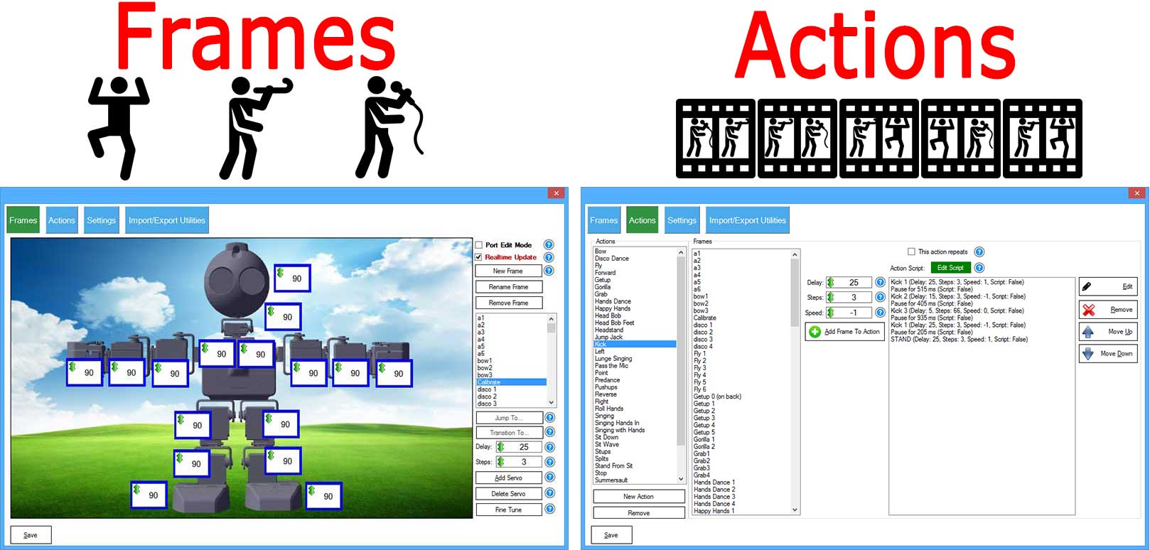
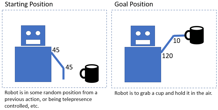
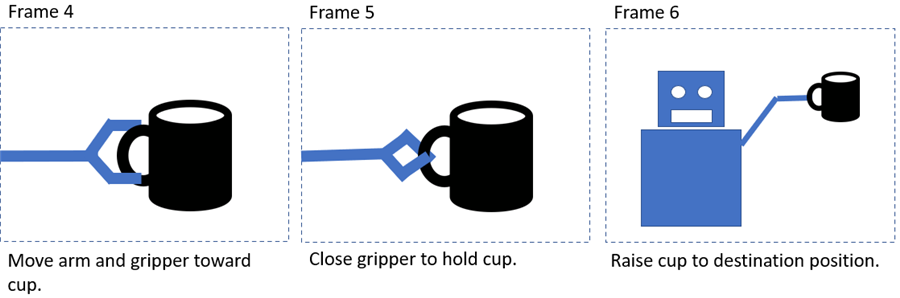
Example: Picking up a cup
Assume you have a simple robot arm with two joints (shoulder & elbow) and a gripper. You may wish to pick up a cup and raise it. This entire motion sequence is an Action consisting of a collection of Frames. Let us first define the start and end of the desired Action. As you can imagine, there are many steps between the beginning and end, with the robot holding a cup. The Auto Position makes this very easy to accomplish by splitting the Action into a collection of frames.
Creating Frames
You can begin by defining the Frames required to complete the Action. The Frames are snapshots of how the robot can achieve the task. Notice in this example, the task is split into smaller frames. Frames are defined rather than having to program every servo movement. Later, the frames are added to an Action to be replayed programmatically.
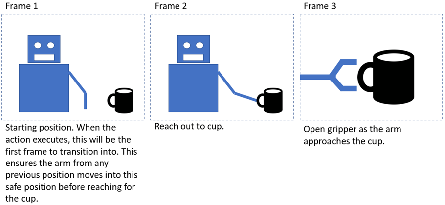
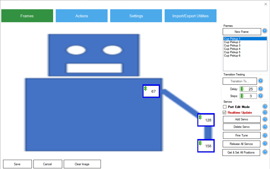
After creating the frames in the Auto Position config menu, you will end up with a list of frames with associated servo positions.
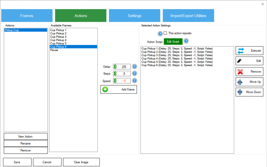
Add Frames To Action
An action is a collection of frames. Each frame in an action will have attributes that define how quickly it will move and any associated scripts. The transition between frames is selected when adding or editing an action. The action "Pick Up Cup" has the associated frames in the example image below.
Step/Delay Settings
Hypothetically, let’s assume a frame moves the robot from this example, the Start frame to the End frame. The Auto Position will perform calculations using the start & end positions to interpret the movement positions. The algorithm will ensure all joint positions simultaneously arrive at their destination position during the transition. This behavior is repeated for the transition of each frame of action.
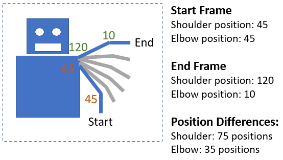
Example: Steps: 5, Delay 20
Using these Steps and Delay values, the Auto Position will send 15 movement commands to the EZB with a 20ms delay between each command. The Auto Position has been determined to send 15 movement commands because the most significant difference between the servo positions is 75. With a Step increment of 5, that leaves 15 movement commands. All remaining servos with minor position differences will use smaller steps, thus arriving at their destination simultaneously. The Auto Position will use the most significant step for the servo with the most significant position difference.
The shoulder will move five positions per command. The elbow will move 2.3 positions per command. There will be a 20ms delay per command. This ensures the shoulder and elbow joint positions arrive together at the destination frame positions.
Tutorial Creating Hexapod Gait
Here is an example of using the Auto Position to program a walking gait for a 3D-printed large hexapod robot. This demonstrates the movement panels' power using additional skills (camera, speech recognition, joystick) to control the movements.
Main Window
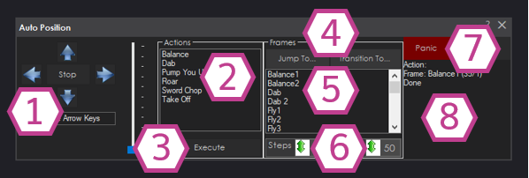
1. Movement Panel
These buttons will allow you to control the directional movement of the entire robot (left, right, forward, reverse, and stop). If you place your cursor in the textbox below, you can use the arrow keys to control the movement direction. Pressing UP will execute the frames in the FORWARD action. When the arrow key on the keyboard is released, the STOP action will execute. With the buttons on the screen, the forward button is pressed, it will keep moving forward until the STOP button is pressed.
2. Action List
This is the list of actions that have been created. Select one and click the execute button to run one of the actions.
3. Execute Button
This button executes the selected action in the action list.
4. Jump To... and Transition To... Buttons
The "Jump To..." button instantly moves the servos into the frame's position selected in the frame list. The "Transition To..." button moves the servos gradually into the position of the frame specified in the frame list. These two buttons move the robot into a selected frame instead of executing an action. An action is a list of frames, so if you wish to move into one frame from the current position, You can use these two buttons—the values. You may also select the Step and Delay values.
5. Frame List
This is the list of frames created so that you may access them individually rather than as an action. Select one and click the "Jump To..." or "Transition To..." Buttons.
6. Step and Delay Values
Adjust these values by clicking and holding the left mouse button or right-clicking them and entering a value from the keyboard. These values are used for the "Transition To..." button of the selected frame—the lower the delay value, the faster the servos transition into the position. The lower the step value, the more steps a servo will take when transitioning to the next position. The higher the step value, the more multiple positions the servo will skip to the desired position.
7. Panic Button
This button will stop the auto position and release all the servos.
8. Status Display
Displays the status of the commands being executed inside the Auto Position skill.
Configuration - Frames
Each frame displays values for all the servo positions (in degrees). You can modify the servo positions, and the robot will respond in real-time. There are two ways to edit servo positions:
1) Left-click and hold on to the degree number value to drag the value up and down.
2) Right-click on the degree number value and the keyboard to type in the value.
*Notes:
- In a frame, the position of a servo is between 1 and 180 degrees.
- If the 0 (zero) position value is selected, this releases the servo from its holding position. If the gearing allows, the output gear can be moved by hand. Selecting the value of 0 for a Continuous Rotation Servo will cause the servo to stop rotating.
- If the servo position value of -1 is selected, the Auto Position skill skips the servo for that frame. The position of that servo is maintained, and nothing is changed until the next frame.
- While designing custom frames for your robot, pay attention to the stress/weight applied to servos. The robot may prematurely damage a servo if too much force is applied during the frame creation. We suggest supporting the robot's weight while moving the servo positions of a frame. Once it looks right, place the robot down to see how it is holding.
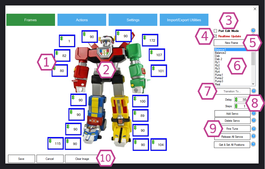
1. Servo Positions
These are the servo positions set up inside a frame. Each number corresponds to a servo position value set up on a specific port. Enable Port Edit mode to see the port number.
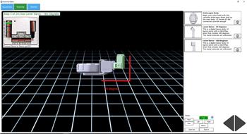
2. Background Image
A background image can be added to represent your robot. Image files (.PNG and . JPG) are supported and will be stretched to fit the background area. The background area is approximately 840 x 512 pixels.
3. Port Edit Mode Checkbox
This checkbox displays the port number above each servo position value when enabled. It also allows the port to be changed by left-clicking on it.
4. Realtime Update Checkbox
This checkbox allows the servo positions to affect the robot in real time. This is very helpful when creating a gait for your robot. You may wish to uncheck this option if you do not wish the servos to move due to correcting incorrect values that may damage the robot.
5. New Frame Button
If you'd like to duplicate a frame, select the frame you'd like to duplicate and press the New Frame button. This allows you to easily continue working on a robot action from the last frame position the robot was in.
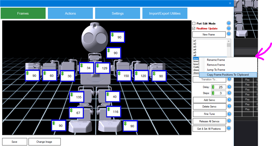
6. Frame List
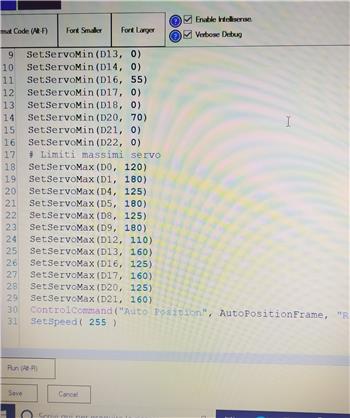
This is the List of created frames containing servo positions. When editing servo positions for a frame, you can right-click on a frame to select the servo positions and copy them to the clipboard. This is useful if you want to create a script for moving the servos later or to make a script for setting servo Max and Min limits. Right-click on a frame and select Copy Positions to Clipboard. Then, paste the clipboard into a script and add the commands to move the servos into position.
7. Transition To... Button
This button gradually moves the servos into the frame selected in the frame list for testing. When creating/editing frames, you can use this button to transition into the frame to test how it would perform when added to an action. The values of Delay and Step will be used for this option.
8. Delay and Step Values
Adjust these values by clicking and holding the left mouse button or right-clicking them and entering a value from the keyboard. When testing transitions to frames, these values are used for the "Transition To..." button. The higher the step value, the more multiples of degrees the servo will skip to the desired position. The higher the delay value, the slower it will take to arrive at the goal positions. These values are not stored or saved with a frame; they are for testing transitions while creating/editing frames.
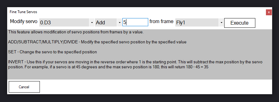
9. Servo Management Buttons
These buttons allow you to add, delete, fine-tune, and release all servos. First, enable the Port Edit mode checkbox to delete a servo, click on the Servo border, and press the DEL key on the keyboard. To fine-tune the servo positions, press the button and use the options available (Add, Subtract, Multiply, Divide, Set to, and Invert) to change the position values.
10. Clear/Change Image Button
This button lets you delete/set your background image for this skill. A background image will help you set up servo positions to match the physical layout of your robot.
Configuration - Actions
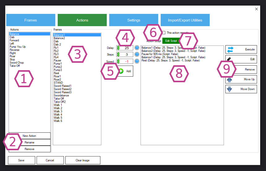
1. Action List
This is a list of created actions. Use the action management buttons to make changes to this list. An action consists of a collection of frames, each with parameters that affect how it transitions between frames.
2. Action Management Buttons
These buttons manage the action list. Add a new action, rename an action, or remove an action with these buttons. You must select the action in the list first to rename or remove that action.
3. Frame List
Select the frame you would like to add to the sequence list. Once selected, you will need to press the Add button.
4. Delay, Steps, and Speed Values
These adjustable values will set the Delay, Steps, and Speed of the frame you will add to the sequence list. These values will transition between each frame in the action list.
5. Add Button
This button adds the selected frame from the frame list and associated Delay, Steps, Speed, Velocity, and Acceleration values and appends it to the Action sequence list. The associated delay/step/speed values determine how this frame will be transitioned from the previous frame when the action is executed. Different servo models and manufacturers will support acceleration, speed, and velocity options. These options will use those parameters if the selected servos support them. Check with the servo model & manufacturer datasheet to see if your servos support these options.
6. This Action Repeats Checkbox
This checkbox will make the sequence list loop infinitely when executing the action. The action will continually loop until another action is executed.
7. Edit Script Button
This button allows you to add a script to the action. If the button is green, no script is present. If it's blue, a script will be run when the action is executed.
8. Sequence List
This list contains the sequence frames (frames + values) that will be run sequentially (top-down) when an action is executed. The list can be modified using the sequence management buttons.
9. Sequence Management Buttons
These buttons manage the sequence list. You can test the action sequence with the execute button. Edit any sequence frame with the edit button. Delete a sequence frame with the remove button. Change the action sequence by moving a sequence frame up or down with the move buttons.
Configuration - Settings
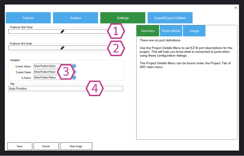
1. Auto Position Start Script
This script will be run before a frame or action is executed.
2. Auto Position End Script
This script will be run after all the frames or actions in the queue have been executed.
3. Auto Position Variables
These variables contain the name of the current action and frame and the status of the auto position skill. If the auto position skill executes a frame or action, the $AutoPositionStatus will be true (1). Otherwise, if the skill isn't running, it will be false (0).
4. Title Field
This field contains the title of the auto position skill. You can change it if you'd like. *Note: Changing the title here will also change the title in the controlCommand() associated with this skill. Any existing references in your code must be updated for the new name.
Configuration - Import/Export Utilities
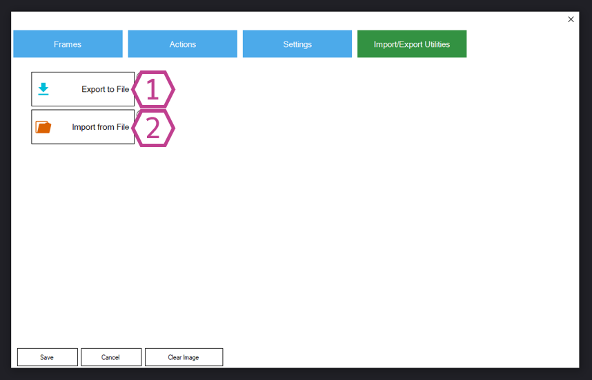
Within the Configuration menu is the ability to Import or Export Actions and Frames to exchange between other auto-position robot skill instances or projects. The import/export is also helpful if you wish to move configuration from the auto position movement panel to the non-movement panel version or vice versa. You can only import frames if the servo configuration matches the existing project for obvious reasons. If the servo configuration does not match, the import utility cannot simply "guess" what servos to assign the new frames. This limits importing and exporting to projects with the same servo configuration.
A message will be displayed if a frame is imported and already exists. Unselect the frame from being imported. The most common mistake is to import the PAUSE frame, which is auto-generated and cannot be removed.
1. Export Button
This button exports an .autoposition file for adding to another ARC project or another auto position skill.
2. Import Button
This button allows you to import both .autoposition and .ezb files into an auto position robot skill.
Auto Position With Movement Panel vs Without
There are two types of auto position skills in ARC. One which has a movement panel, and one without.1) The Auto Position With Movement Panel skill contains a movement panel, which will execute the robot gait actions for direction movement. Like all movement panels, there can only be one instance of this skill. There are predefined actions for movement directions (forward, reverse, left, right, and stop) to which you can assign frames. You can add gait frames to each action to have your robot move in a customized fashion when any control calls the robot to move in a direction.
To control an Auto Position with Movement from a script, specific commands require ControlCommand(). View the cheat sheet for available ControlCommands, or use the script movement commands (Forward(), Left(), Right(), Stop(), Reverse()).
2) The Auto Position Without Movement Panel skill can have multiple instances and does not control directional movements like a movement panel. This skill also accepts script controlcommand()s.
How to Use Auto Position Skill
1) Add the Auto Position Skill to your ARC project (Project -> Add Skill -> Movement Panels -> Auto Position Movement Panel).2) create frames for your servo motor(s) in the Configuration menu. Each frame is a servo pose in a collection pose to achieve a result.
3) In the Configuration menu, create a new action and add the frames you've created. Add some pause frames between your frames if needed. Adjust each frame's delay/steps/speed values to achieve the desired transition results between frames.
4) Select an action and press the action button in the main window.
Code Samples
Every Auto Position ControlCommand() is published in the Cheat Sheet tab. Pressing the Cheat Sheet tab will display the ControlCommands() for all skills, including the Auto Position. To execute an Auto Position from a script, you would use commands such as:
ControlCommand("Auto Position", AutoPositionAction, "My Action 1")

ControlCommand("Auto Position", AutoPositionFrame, "My Frame 1")

ControlCommand("Auto Position", AutoPositionFrame, "My Frame 1", 50, 3)
Videos
Resources
There are utilities for importing and exporting auto-position files in the Configuration menu. The Import/Export tab will contain buttons to launch the specific utilities.Related Tutorials
Sabertooth+Kagaroo+DC Motors As Servos
The Robot Program Episode 009: Getting Six To Move
The Robot Program Episode 006: Introducing ARC
The Robot Program Episode 003: Getting JD To Move
The Robot Program Episode 021: Detect Face And Wave -...
The Robot Program Episode 020: Detect Face And Wave -...
Related Hack Events
DJ's Third Hack Night
PWM Servo Position Feedback (Read Servo Position)
DJ's 9Th Live Hack - Raspberry Pi + Dynamixel... Together...
Robot As Puppet To Control Another Robot By Reading Servo...
The Lattepanda Robot Hack
DJ's 6Th Live Hack Event (Raspberry Pi & Neopixel With...
Related Questions
Reverting Servo In Script Or Movement Panel
Strange Issue With Servo Speed/Delay/Steps And Usb Camera
Calibrate Problem

Upgrade to ARC Pro
Become a Synthiam ARC Pro subscriber to unleash the power of easy and powerful robot programming
Given a specific location in 3D space (I have programmed my Oak-D camera to give me a location coordinate in 3D space), I am attempting to move my robot's hand there. Is there a way to do this with this movement panel? Please assume that the location will change. For instance I hold a bottle in my hand and I wish the robot to grab the bottle from me.
The Auto Position uses pre-defined frames. While frame positions can be added programmatically, they cannot be altered programmatically.
What you want to do would have to be done with some math and specifying servo positions directly. Due to the unknown parameters of the robot's configuration, this can't be automated. But, it is something possible to do with math. If you have the 3D coordinates of an object, the joint positions will have to be calculated by the joint lengths to relate to the coordinates. This is how a CNC machine would work.
So then it’s a feature request? A FK and IK feature? Plug in joint lengths and DOF, and the final location (x, y, z) for the claw/hand as inputs? I am guessing it’s not a simple task or you/your guys would have already added it.
Sorry, it’s impossible because every robot has a different configuration. There’s no way a robot skill could be created for infinite configurations. It’s something that would require math specific to the robot configuration. Somehow identifying the position relative to some other arbitrary value in 3D space. Maybe you’d have to figure out some servo values based on fixed points and map that to the arbitrary 3d Cartesian points of your camera?
Im not really sure - have you googled to see any ways others have done it?
*edit: this is the best article that’s easiest to understand of what I’ve found by searching. I use google as my preferred search engine: https://fl0under.github.io/robotics-notes/
he outlines a lot of details that need to be considered in the process. This is also why it’s impossible to create a robot skill that encompasses an infinite robot arm configurations. But it’s a good read to help where you can begin.
a good start is to merely use the x and y coordinates (ignoring depth) to align the hand to the object. If you can do that much, then the depth won’t be much more work.
I’m guessing the number of joints and lengths of each joint will make the process harder.
This skill is one of my favorites but had a couple questions. Is there a way to couple two motors so that they can change values at the same time inside of the skill itself (frames). I understand the master/slave while using servos outside of this skill and it would be nice to have that working inside of this skill because you cannot do realtime update because if the motors are coupled together they would be fighting each other till you change the numbers on both of them. The other question is can you use bluetooth joystick at the same time as you are in the frames mode. Since I am using steppers and the numbers are in the tens of thousands the little arrows are not of any use because they only move by 1s or is there a way to manipulate that and multiply the ratio?
Sounds like you should be using a different Movement Panel for movement and use the regular auto position.
Thought about it but even with the regular Auto Position it still doesn't tie two or three motors values together for real time movement. I have been making due by turning it off temporarily and then changing values then turning it back on. Was just mentioning it to possibly add it for the next update. The reason for bluetooth joystick or or hot keys while using Auto Position is to quickly maneuver end effectors, arms etc to the position and then just save that position. I am doing it now outside of Auto Position and writing down the values and adding them when I go back in.
What movement type is your wheels? Is it a dc motor with hbridge? Continuous rotation servo? Etc..
Everything I do from here on out is steppers I have found a way to manipulate the Blockly code to move it the speed that I want in forward reverse, etc. moves I am looking for high accuracy, and the steppers work for me.
I think I may have spoken a bit too quickly. As far as movement on the floor surface the type of motor that I use depends on the distance. If it is less than 40 ft then it will be steppers. If it is hundreds of feet the will be using sabertooth driver. The bot that I have in my garage using The Better Navigator is using the sabertooth but the bot moving side to side to feed the 16' gantry will be using steppers.I am foreseeing the steppers counting to 65k and then I will need to do a a restart to 1 and start over again.