Almostrodney
Canada
Asked
— Edited
Good afternoon everyone,
Did a search and couldnt find anything on this.
My robot has a head that rototes on a 72 tooth gear belt driven from a smaller 18 tooth gear (4:1) with a continuous servo attached and this servo is connected to a variable 10 turn 10K resistor. Good afternoon everyone,
I dont want the head to turn more than 180 degrees from central position, so i make that x2 turns of the servo either way.
from what ive learnt i believe i need to somehow convert the resistance to a PWM, but i have no idea where to start with that.
If someone could point me in the right direction i would be very greatful
 Thanks?
Related Hardware EZ-B v4
Related Control
Continuous Servo

Hello @Almostrodney,
You have a few options:
You should be able to scour youtube, google, and the Synthiam pages to find more info on each topic.
Thanks for the reply Jeremie,
As i said above, im using the Multi turn potentiometer (10 turn 10k) and have searched, but i dont know enough about them to know where to start.
Do i use ADC? how do i get it to relate to PWM? where in the software do i do this?
Im happy to do my research but the tutorials are scares on these.
Oh I apologize, I didn't see the 10 turn pot info. In that case, yes, you can use an ADC to measure the voltage.
It depends on what voltage the Pot is getting but you should be able to connect a wire to the wiper of the Pot and get your analog voltage from there. I'd measure the voltage of the wiper to see what your min and max voltage are (fully stowed to fully retracted).
If you are using an arduino to measure the max analog voltage it could measure 0 to 5V scale. If it's an EZ-Bv4 it would be 0-3.6V (with protection upto 5V) if it's an IoTiny there's not 5V protection so I'd say 0-3.3V max.
I'd recommend using a standard HDD servo and removing the stopper and removing the POT.
Then, attach the wires from the POT to the new POT
Voila, you have a servo without having to write a pile of code because it'll all be self contained. That's how the InMoov joints work. They remove the POT and locate it on a joint.
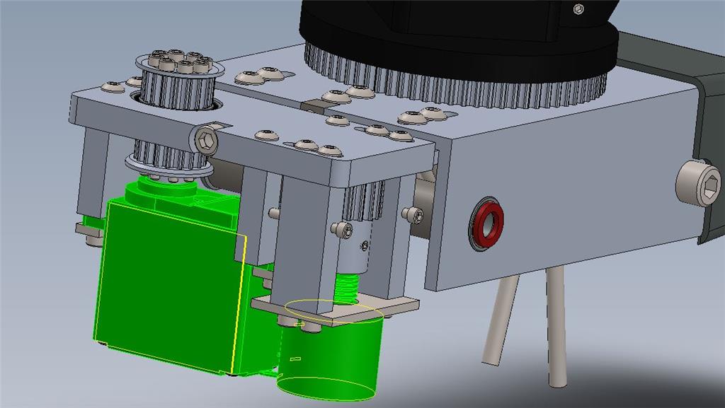
So yea, I actually designed this and it is the Neck Assemble and Left/Right Drive system for the Johnny Five Robot. The system uses a modified Hitec HSR-5995TG servo (or current exact replacement). Remove internal rotation limit pin from Output Shaft Gear and remove internal feedback Pot. Correctly rewire Pot connections on servo PCB to external 5 turn Pot. The design as pictured and designed uses a Dale Vishay (535-1-502) 5 turn Pot and will safely allow for just over 360 degrees of neck Rotation as the servo output Pulley to Neck Pulley is a 4:1 Ratio. If only 180 Degrees of rotation is desired, I would instead suggest using the 3 turn version of this Pot or you will actually have less fine positional control as you will be using much less of the total Pot's wiper Arm resistance range. The exact servo chosen was done as it needs to be able to effectively control the weight and moving mass of the Head which is very heavy and rotate it a Screen accurate speeds.
You may wish to join a Facebook Group which I often reply to (Since your obviously working on a J5). FYI, I'm a member but, I do not run that Facebook Group.
https://www.facebook.com/groups/1453987614832892/
You can also Visit our Teams Website here, https://input-inc.com/ FYI, I do own and administer this site.
Me and my Team have decided and are currently using the EZ-B controllers in all Johnny Five builds. I would love to be able to talk to DJ about a problem that I was just made aware of this morning concerning unexpected servo movement during power-up of the controller. In the case of the Full size Johnny Five....this poses a huge safety issue for us.
Hope this all helped!
P.S. Almostrodney, Me and my Team plan on freely releasing the full updated design files for the entire J5 Robot at the beginning of 2020. You are currently working from our old (Build at your own risk....LOL) not built nor tested prototype designs. So if you do plan to just keep building your J5, you will likely find areas where the old and new designs are not compatible nor able to otherwise be modified to work with one another.
Hi Terry, its Ryan Howard who has been building a J5 in Nottingham, UK!
Didn't realise you was on here, and thanks for the response :)
After consideration I was going to try a winch servo (cant remember which) and give it a try until the full files are released.
I also get the sudden movement of servos when I turn it on, but thought it was just a beginning setting I hadn't set yet, but yeah Its a problem for me too, particularly the eyes going to a position out of range.
The twitch experienced by the servos you are using is because of the servos. Low quality servos will twitch when power is applied. There’s no solution other than to not apply power :). When I was ceo of ezrobot, I pushed for us to have our own servos to avoid that issue - also to have stall protection, and of course super silent operation. You’ll find significant differences between lower quality and higher quality servos. My recommendation is to replace all the servos with higher quality or replace the ones that will reek the most havoc.